ER-Force Team Description Paper for RoboCup 2009
Peter Blank, Michael Bleier, Sebastian Drexler, Jan Kallwies, Patrick Kugler, Dominik Lahmann, Philipp Nordhus, Christian Riess, Thaddäus Swadzba, Jan Tully
Robotic Activities Erlangen e.V.; Chair of Pattern Recognition, Department of Computer Science University of Erlangen-Nuremberg; Martensstr. 3, 91058 Erlangen, Germany
Abstract This paper presents an overview description of ER-Force, the RoboCup Small Size League team from Erlangen, Germany. The current hard- and software design of the robots, the vision system and strategy software are described. On the hardware side, we have a new solenoid kicker and report about our experiences with a pneumatic kicker in the 2008 design. Additionally, the color separation in the vision system is now done with a direct lookup table to avoid costly computations. The artificial intelligence has undergone a complete rewrite and is currently based on a reinforcement learning approach for the assignment of roles. Furthermore upcoming changes and improvements will be outlined.
Introduction
This paper describes the RoboCup Small Size team ER-Force from the University of Erlangen-Nuremberg. The team was founded in September 2006 on the initiative of two students who formerly participated successfully at RoboCup Junior competitions. The goal was to create a interdisciplinary research project involving students from computer science, mechatronics and electrical engineering. To keep the team together and to foster robotics in Erlangen we decided in 2007 to found a non-profit association called "Robotic Activities Erlangen e.V.". This association was since engaged in many robot-related activities including the founding of two new Robot Junior teams at high schools in Erlangen. In 2007 we successfully participated at the RoboCup German Open in Hannover, Germany and ranked fourth. We also successfully qualified for the RoboCup 2008 in Suzhou, China but could not participate due to the high travel costs. At the RoboCup German Open 2008 in Hannover, Germany we achieved a second place, our best result so far. Our current goal is a successful participation at the RoboCup 2009 in Graz, Austria.
The following sections describe the various components of our current Small Size team ER-Force, including new developments and planned extensions. The team consists of six robots (including one spare), a vision system to localize the robots on the field and a strategy module. The robots are completly remote controlled by the offboard computer software. The hardware and firmware architecture of the robots will be described in section 2. The vision system will then be explained in section 3 followed by the strategy module in section 4. Finally we give a conclusion about the new developments we would like to test at RoboCup 2009.
Robot Architecture
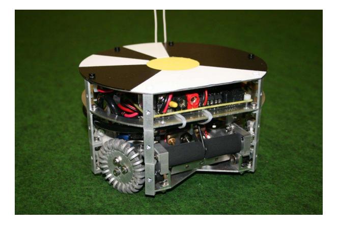
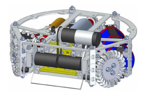
The design of our 2009 robots is shown in Fig. 2. This year we put even more emphasis than before on a weight saving construction. The six robots are identical in construction and the chassis consists of laser-milled aluminum plates connected with angle brackets. The lower part of the chassis contains the motors with wheels, the kicker with capacitor and the dribbler, while the upper part is completely reserved for the electronics. The robot design is fully rule compliant and has a maximum diameter of 175 mm and a maximum height of roughly 100 mm. The robot covers less than 20% of the ball along its z-axis projection at all times.
Drive
To allow for an optimal mobility the ER-Force robots use an omni-directional drive-system (see Fig. 2). It is similar to other Robocup Small Size teams like [1], but uses only three wheels.
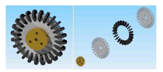
The three wheels were custom built to provide optimal grip in the rotation direction and minimal resistance in any other direction (see Fig. 2). Each wheel is driven by a DC motor (Maxon A-max 22) with integrated planetary gear, where the motor speed is controlled using a pulse-width-modulated signal (PWM-signal). The actual speed of the wheels is monitored using quadrature encoders attached to the motor shafts. This information is used to adjust the motor PWM-signal to achieve the desired wheel speed using a proportional-integral (PI) controller which is running on a microcontroller at a control loop speed of 100 Hz. This system will be further improved using a cascaded controller and a yaw rate sensor.
Kicker
Electric solenoid kickers are very common in Robocup Small Size teams [1]. To avoid the high voltages and large capacitors involved in such a system we evaluated a pneumatic kicker in our 2008 design. This kicker consisted of 4 air tanks, a pneumatic cylinder and an electronic valve. The system was pressurized to a maximum of 20 bar before each game with an external compressor. With a full tank this system could shoot at a speed of up to 5 m/s. However the design turned out to be too unreliable, as the high pressure often caused a loss of air or broken hose connections. In addition the poor shooting capabilities did not satisfy our expectations. For this year an electric solenoid kicker is under development, which consists of a high voltage capacitor with a capacity of 4900µF and the solenoid kicker itself with a resistance of 1.5Ω. The capacitor is charged by a step-up charging circuit to a voltage of up to 200 V. To activate the kicker a Power MOS-FET is used to drive the high current and voltage load. The new system is currently capable of shooting the ball at a speed of up to 7 m/s. For reliable ball detection the new kicker will also use a light barrier. A chip-kicking device using the same capacitor but a second solenoid is currently in development.
Dribbler
The dribbler system in our current robots is placed above the kicking device (see figure 2). Its purpose is to allow ball handling consistent with the Small Size League rules, e.g. driving backwards with the ball. It consists of a rubber coated bar driven by a small DC motor (Maxon A-max 19). This bar was designed to exert backspin on the ball and keeping it in position. The current dribbler design proved to be insufficient, as the rubber bar failed to exert enough force on the ball. The bar is currently not mounted at an optimal height due to construction restrictions and will be replaced by a better design.
Controllers
Our current robots are using three microcontrollers. An ARM7 receives the commands from the radio module, runs the controller loop, and generates the PWM signal. The encoder signals are evaluated by an ATmega8, which is connected to the ARM7 via an SPI bus. Our new solenoid kicker is actuated by another ATmega8 located on a different board. In order to provide a clean and consistent interface to the different controllers in use, we wrote a library that encapsulates hardware specific features such as PWM-signal generation or bus communication.
Radio Communication
After our strategy module (described in chapter 4) found the new destination positions for the robots, the relative movement speed (in robot-local coordinates) is calculated, and sent via USB to the radio sender. The sender has an ARM7 microcontroller which simply receives the data from its USB interface and sends it to the robots using an NRF24L01 radio transceiver. The generated radio packets have a variable size of 4 to 24 bytes, depending on the actual commands sent.
Vision System
As latency is one of the main aspects in the RoboCup Small Size League, the vision system has to be highly optimized. Our two cameras generate a datastream of about 80 MB/s in which colors have to be segmented and objects have to be found and tracked. This is done by a parallelized algorithm running under GNU/Linux on an Intel Core 2 Quad CPU. An overview of the processing steps involved in the vision system can be seen in Fig. 4.
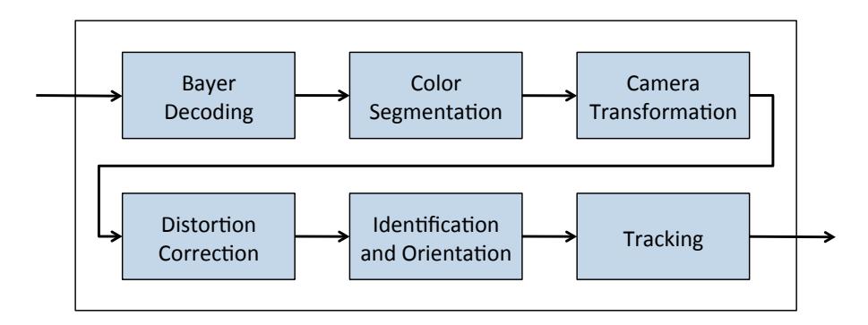
Image Acquisition
Our vision software captures images from two AVT Guppy cameras mounted above the field. They are connected to a desktop PC via FireWire IEEE 1394a and deliver one frame every 25ms (40Hz). 4.8mm lenses are used in order to get a view of the entire field from a height of 4m.
Bayer Decoding
The captured images are coded in an 8-bit Bayer pattern, which has to be decoded before we can search for colors. To achieve this we use two different methods, both from libdc1394. At first the entire image is decoded with a bilinear filter, which is very fast but provides poor results especially on edges. After objects have been found that need to be identified (i.e. our own robots) we decode the area of interest again using the AHD filter (see [2]), which provides better results, but is much slower than the bilinear filter.
Color Segmentation
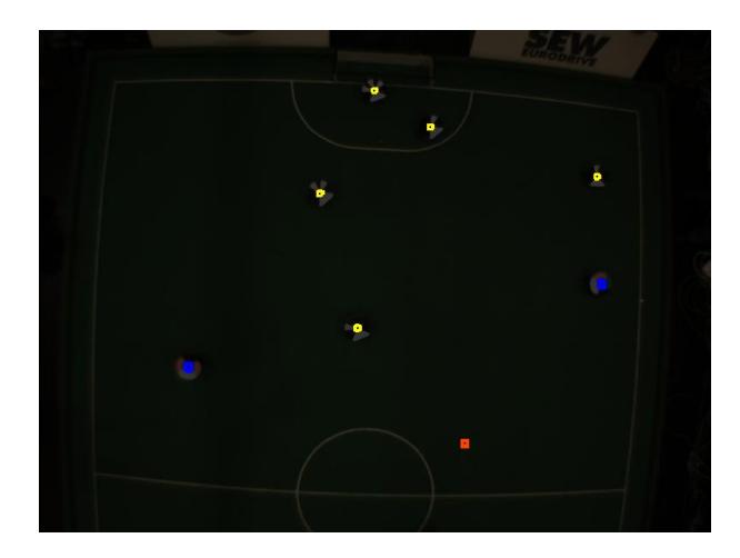
In order to find the objects (ball and robots) in the camera images a color segmentation is needed. In the previous years we have used a simple YUV-based range comparison to detect the colors. If the color of a pixel (in YUV color space) is inside a specified range, it is believed to be of a certain color. This turned out to be insufficient, because it could not handle simple relations between the color components. Therefore a new approach was implemented. A look-up table is used to categorize each pixel as yellow, blue, orange, or other. This table is generated before the game by a Lua script [3] which compares the relations between the RGB components.
The script for the ball could look like this:
if r > 1.3 * g and r > 2.0 * b and r > 75 and b < 60 then
    setColor(r, g, b, orange)
end
To remove outliers and to close gaps different morphological filters (opening and closing) are then applied for each color. Afterwards connected regions are found and the center of each region with a suitably chosen minimum size is transformed into global field coordinates as described in the following paragraphs.
Distortion Correction
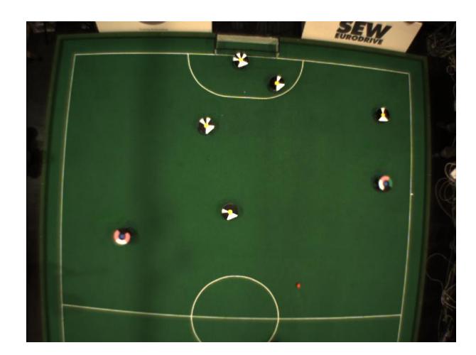
The images from our cameras are affected by a radial barrel distortion due to the wide field of view of our lenses (see Fig. 5). To correct this distortion a scaling of the image positions pimage towards the image center cimage has to be performed:
$$p_{\text{corr}} = c_{\text{image}} + s \cdot \left( p_{\text{image}} - c_{\text{image}} \right)$$
To improve the performance and to reduce the latency of the vision system this correction is only done for each robot or ball position found in the color segmentation step and not for the entire image. The scaling factor s depends on R, which is the distance of the point pimage from the image center normalized to the image size. It is calculated using a polynomial displacement function, which models the barrel distortion:
$$s = a \cdot R^4 + b \cdot R^2 + c$$
$$R = \frac{||p_{\text{image}} - c_{\text{image}}||}{||c_{\text{image}}||}$$
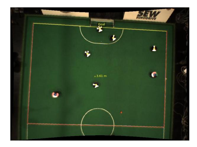
The parameters a, b, and c have to be estimated either manually or automatically. As the radial distortion is a property of the camera optics, the correction parameters remain static when repositioning the cameras and have to be estimated only once. So far the parameters have been estimated manually using the field lines in a distortion corrected image (see Fig. 7). An automatic estimation using a test pattern (similar to [4]) is currently under development and will provide more exact parameters.
Camera Transformation
The corrected object positions need to be mapped to their corresponding real field coordinates. This is realized by transforming them by a perspective projection matrix. The matrix is calculated according to [4] by solving a system of linear equations containing the known relations between the field coordinates and the image coordinates of four points (the corners of a field half). Whenever the camera position or orientation changes, the image positions of these points have to be selected either manually or automatically by a line detection algorithm.
Identification and Orientation
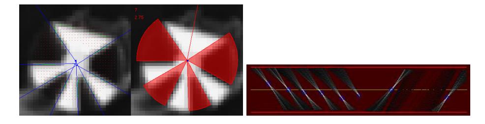
After the positions of the ball and all robots on the field are known we have to get the unique identification number and orientation of our robots. This information is required to control the individual robots. To solve this task each robot carries a plate containing a unique black and white pattern (see Fig. 1). The neighborhood of the robot position is analyzed and a Hough Transformation [5] is used to find the edges in the image, as shown in Fig. 8.
In order to find the edges the image is first scanned radially around the robot center for black/white transitions. The image coordinates of these positions are then transformed into a Hough space. Each point in this space corresponds to a line in the original image. The angle of the line and its distance to the origin are the coordinates of the points in Hough space. Each point in the original image corresponds to a sine wave in Hough space. Each point of this wave in turn represents a single possible line through the original point (see Fig. 8 right). After each possible edge point is transformed a search for maxima is performed in the Hough space. These points with the highest intensities correspond with high probability to edges and are used to identify the robots and to obtain their orientation.
Tracking
As the ball may be occluded by robots or objects may not be found due to failures in the color separation step (e.g. camera flashes), we need to track the position of each object. This is currently implemented by using the position of an object in the current frame and in the previous frame to estimate the velocity of the object. If an object gets lost, then its last known position and velocity are used to estimate the current position of the object. As this approach is not reliable in some cases (e.g. occlusion) we are currently evaluating different approaches, based on Extended Kalman Filtering and Particle Filtering.
Strategy Module
The strategy module of our team was initially a simple finite state machine. Unlike several other teams we are currently working with a reinforcement learningbased approach that determines the number and kinds of roles that are distributed in the game state under examination. In the future we plan to "rehabilitate" the finite state machine in a much improved version and to reimplement the machine learning unit towards the analysis of the opponent.
Overview
The artificial intelligence in the RoboCup Small Size team ER-Force is located between the vision system and the motion control system. It communicates with the vision subsystem and the motion control module via UDP. Our approach in the 2008 system consisted of a simple finite state machine. A specified number of offensive players tried to obtain the ball, pass and shoot at the goal. Referee decisions switch the state immediately to corresponding referee states. While this was a sufficiently effective strategy for the beginning, it did not perform well against teams with an explicitly modeled artificial intelligence. In the past months we tried a different approach: The behavior is modeled in three layers that are executed one after another. They are able to overwrite or modify decisions that are made by previous layers and are roughly inspired by Brooks' subsumption architecture [6]. The involved layers are:
The strategy layer controls the behavior during regular gameplay. This involves all play decisions like offensive and defensive actions. The process of decision making is at this time done by the application of a reinforcement learning approach.
The referee layer interferes if the game is stopped and handles the given referee situation, like keeping the minimum distance to the starting point.
The collision avoidance layer modifies the commands from the other two layers such that it complies with the general demand of obstacle avoidance. It is implemented using the ERRT path finding algorithm [7].
The architecture of the first layer is described in more detail in the following. Although it works much better than the simple finite state approach, we are currently working on an improved architecture. This new approach is briefly sketched in the last subsection of this chapter.
Strategy Layer
The decision making process starts with the feature extraction in the preprocessing step. Afterwards a tactic is chosen that consists of several roles, and finally the roles are assigned to the robots.
Preprocessing - The preprocessing provides the necessary data for the decision making process. On one hand this involves an interpretation of the data, e.g. the detection of the opponent's goalkeeper or the robots' distances to the ball in order to estimate which team is in ball possession. Additionally, some features are computed that describe the game state more precisely. These features are:
Distribution based features: The position of the ball is expressed as a single number between 0 and 2, since it is in one of three areas, either in front of the own goal, in the middle of the field, or in front of the opponent's goal. Additionally, the distribution of a team is expressed as a single number between 0 and 4 that encodes the number of robots in each half of the playing field.
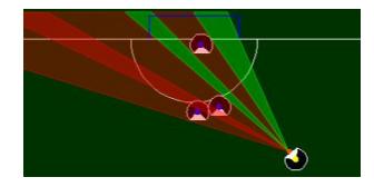
A measure for the probability that the robot that currently holds the ball may score a goal, based on the width of unprotected area between him and the goal as shown in the example in Fig. 9. This is also computed for a second attacking robot, in case that the robot who currently holds the ball passes the ball over to this second attacker.
Although these features are only a very rough approximation of the game state, they allow immediate offensive or defensive actions near the two goals. To keep the feature space easily manageable we omitted features that further describe the middle of the field.
Roles - The described decision unit assigns numbers to roles. These numbers represent how many robots should fulfill a specific role. Available roles are:
- goal defenders: robots that directly protect the goal
- field defenders: robots that try to intercept passes
- ball grabber: robot that runs for the ball
- attacker: robot that shoots at the goal (when in ball possession)
- pass player: robot that plays a pass (when in ball possession)
- dribbler: robot that dribbles (when in ball possession)
- runner: robot that assists offensive moves, e.g. to receive a passed ball
Decision - Depending on the team that currently controls the ball an offensive or defensive role distribution, in the following referred to as tactic, is chosen. This decision is made using a reinforcement learning approach, a well known algorithm in machine learning research (see e.g. [8, 9]). Our notation roughly follows [8]. In the following, we briefly outline the learning problem, our reward function and the practical implementation. By using reinforcement learning, the game is divided into discrete time steps i, the state space S, and the action space A. At time t, let the state $s^t \in S$, the action $a^t \in A$ and a reward for this particular action $r_t$. The aim is to learn a general behavioral rule, called policy, $\pi : S \mapsto A$ that maximizes the cumulative reward function
$$V^{\pi}(s_t) \equiv \sum_{i=0}^{\infty} \gamma^i r_{t+i}$$
where γ, 0 < γ < 1, values policies higher that lead to an earlier reward. One big advantage of reinforcement learning is that the learning process needs no supervision in the stricter sense, but only a reasonably chosen reward function that can be applied during the game. We implemented the Sarsa(λ) algorithm [9] to be able to apply this reward already during the game. Our reward function evaluates to ±5 points, +5 if the ball is in the opposing half of the field and −5 if it is in our own half. Additionally, a reward of ±1000 is applied for goals for us or against us, respectively. As parameters, we have empirically chosen γ = 0.8725, λ = 0.3 and as an additional learning step-size parameter for the Sarsa(λ)-algorithm α = 0.375. Usually the best π is chosen. But to learn new possibilities there is a 10% probability that a random (valid) role assignment is chosen, and consequently the action $a^t$ that belongs to reward $r^t$ is taken in the next step. The decision unit is trained with a bootstrapping-inspired technique through simulated games against other decision units. These sparring partners either operate on the same principle or work with a different approach, e.g. the older finite state machine by our team. It is also possible to modify the learned behavior online during the game. Each chosen tactic contains roles for the team like how many robots should stay on defense, and whether a robot that controls the ball should dribble, play a pass or shoot at the goal. These roles are greedily distributed among the robots according to their current positions.
Improvements
Although our current strategy is much better than the one we used in the last year, it has its shortcomings. One point is its currently poor configurability, and another point is the question, if we can do better with machine learning if we were using it on the behavior of the opponent rather than the general situation. In order to address these issues, we are currently working on the following improvements: Outsource several configuration-related methods in the Lua scripting language [3]. After our positive experiences with Lua for the color table generation we would like to extend its use to the strategy module. Return to the state machine? We are planning an upgrade of our finite state machine approach. The new state machine should feature a cascade of smaller state machines with partially randomized transitions. The machine learning part shall analyze the opponent's moves instead of the general game situation.
Conclusion
We changed a lot on our robots in the past year and are eager to test them in a competition against a large number of other teams. The shooting device is now a solenoid kicker, the communication is improved and the artificial intelligence is significantly further developed. Additionally, we have a full schedule of tasks until RoboCup 2009 in order to present an innovative and pleasing to watch robot soccer system.
References
- Bruce, J., Zickler, S., Licitra, M., Veloso, M.: Cmdragons 2007 team description. Technical report, Tech Report CMU-CS-07-173, Carnegie Mellon University, School of Computer Science (2007)
- Hirakawa K., Parks, T.: Adaptive homogeneity-directed demosaicing algorithm. IEEE Transactions on Image Processing 14(3) (2005) 360–369
- Ierusalimschy, R.: Programming in Lua. Lua.org (2006)
- Rojas, R.: Calibrating an Overhead Video Camera. Freie Universität Berlin. (2005) Availiable at http://robocup.mi.fu-berlin.de/buch/calibration.pdf.
- Niemann, H.: Klassifikation von Mustern. Springer, Heidelberg (1983)
- Brooks, R.A.: How to Build Complete Creatures Rather than Isolated Cognitive Simulators. In VanLehn, K., ed.: Architectures for Intelligence. Lawrence Erlbaum Associates Inc. (1992) 225–239
- Bruce, J.R., Veloso, M.: Real-Time Randomized Path Planning for Robot Navigation. In: Intelligent Robots and Systems, IEEE/RSJ Intl. Conf. on. Volume 3. (2002) 2383–2388
- Mitchell, T.: Machine Learning. McGraw-Hill (1997)
- Sutton, R.S., Barto, A.G.: Reinforcement Learning: An Introduction. The MIT Press (1998)