PlasmaZ Extended Team Description Paper
Chitchanok Chuengsatiansup, Thiraphat Charoensripongsa, Kanit Wongsuphasawat, Komsit Rattana, Pawawat Doungsodsri, Aphilux Buathong, Kittipat Wejwittayaklung, Manop Wongsaisuwan, Wittaya Wannasuphoprasit
Department of Computer Engineering, Chulalongkorn University; Department of Industrial Engineering, Chulalongkorn University; Department of Mechanical Engineering, Chulalongkorn University; Department of Electrical Engineering, Chulalongkorn University
http://www.eic.eng.chula.ac.th
Abstract This document describes more detailed design in both hardware and software aspects of the currently developed Plasma‐Z soccer robots. The hardware part includes vision equipments and the mechanical system of the robot. The software part contains AI layers and vision system. We also describes how hardware and software modules work together to control the robots. Additionally, we provide an example of a situation and explain the response of our system.
1) Introduction
Plasma‐Z is a robot soccer team from Engineering Innovator Club, Faculty of Engineering, Chulalongkorn University, Thailand. Plasma‐Z has joined the RoboCup Small‐Sized League since 2003 and has won the RoboCup Thailand Championship for 6 consecutive years.
Moreover, in the international level, Plasma‐Z has joined World RoboCup Championship since 2003. Plasma‐Z has showed significant improvement since we almost reached the quarter final at Osaka RoboCup in 2005. Later, we won the third place and technical challenge at Bremen RoboCup in 2006, and won the second place at 2007 Atlanta World RoboCup. Currently, Plasma‐Z was the champion of World RoboCup Small‐Sized Robot League at Suzhou, China, 2008.
In Section 2, we give the details of the hardware parts of both the vision system and the robots. The basic mechanical components of the robots are described in details. We also discuss about the background idea of how and why all components are chosen. The electronics design of the robots is also elaborated. The software parts of the system are explained in Section 3. These include the software for the vision system and the artificial intelligence system. For examples, the topics of vision calibration, networking, motion control, simulator, and playing strategies are discussed in this section. Conclusions are given in Section 4.
2) Hardware
Hardware section covering vision and robot systems.
2.1 Vision Hardware Component
Our vision consists of two Stingray F‐046B/C video cameras, space‐saving IEEE 1394 SVGA C‐mount cameras equipped with a highly‐sensitive SONY 1/2 progressive CCD sensor. At full image resolution, the AVT STINGRAY F‐046B/C offers up to 61 fps.
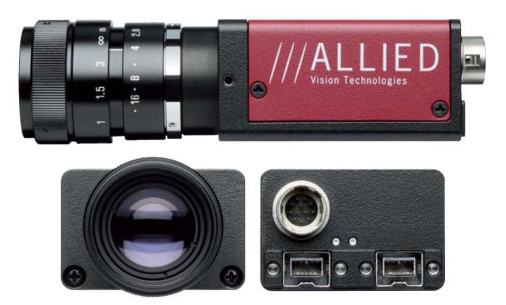
AVT STINGRAY F‐046B/C Technical Specifications
| AVT STINGRAY F‐046B/C Technical Specifications | |
|---|---|
| Image Device: Type 1/2 (diag 8mm) progressive scan SONY IT CCD, ICX 415 | Resolution Depth: 8 bit / 14 bit (16 bit in High SNR mode) |
| Effective Picture Elements: 780 (H) x 580 (V) | Picture Size: 780 (H) x 580 (V) |
| Digital Interface: IEEE 1394b (S 800 daisy chain) | Transfer Rate: 100, 200, 400, 800 Mbit/s |
| Frame Rates: up to 61 fps (full frames) | Gain Control: Manual: 0‐24 db; Auto Gain |
| Shutter Speed: 30 µs ‐ 67 s; Auto Shutter |
More specification can be found at Allied Vision's website: http://www.alliedvisiontec.com/avt‐products/cameras/stingray/f‐046‐b‐bs‐ c‐fiber.html
2.2 Robot
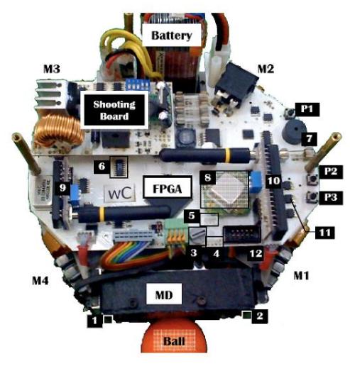
Our robot's hardware design can be categorized into two main systems: mechanical system and electrical system. These two systems have to be designed so that they are compatible with each other for the best performance.
2.2.1 Components
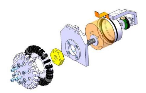
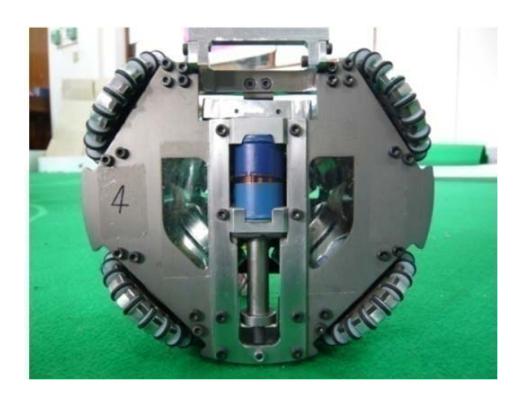
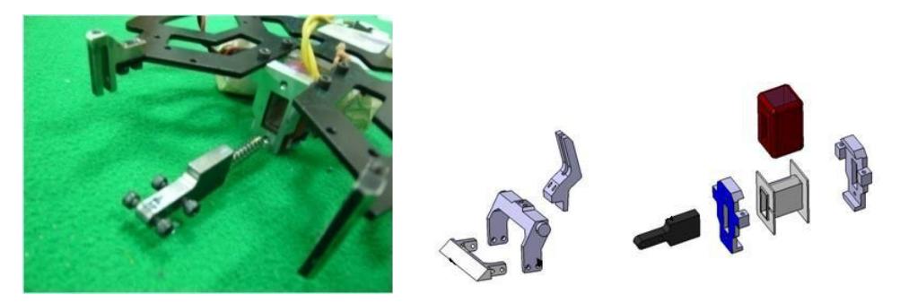
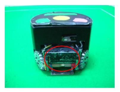
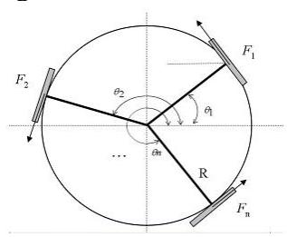
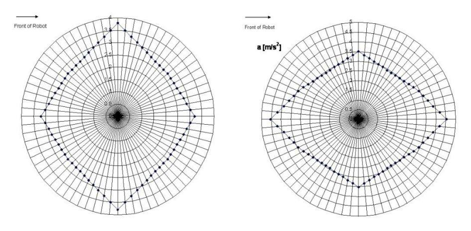
The mechanical system is divided into five subsystems: a driving system, a flat‐kick system, a chip‐kick system, a dribbling system and a robot's structure system.
2.2.2 Electronic Design & Fabrication
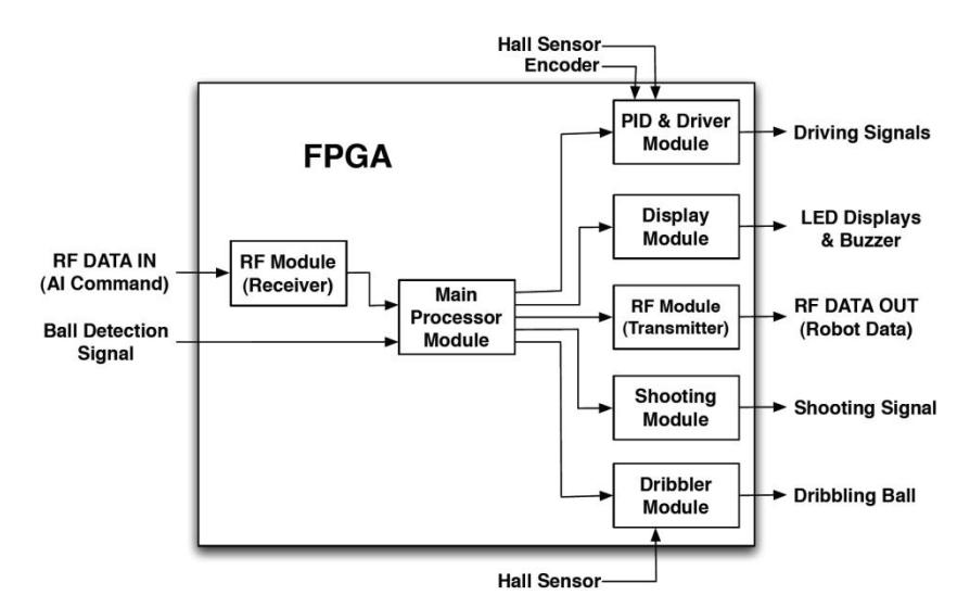
2.2.3 FPGA Design
2.2.4 Mechanical Design & Fabrication
In this section, we discuss more details about our mechanical systems.
2.2.5 Batteries
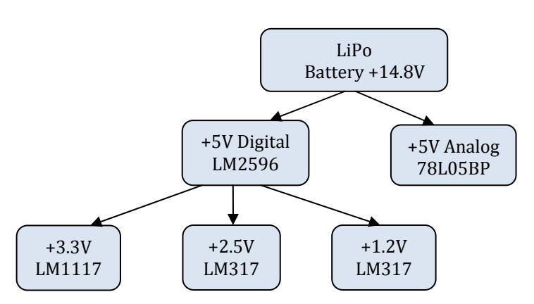
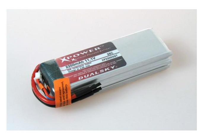
Lithium polymer battery (LiPo) is chosen to be the main power supply. The model XP18004GT from the Dualsky holds the electrical specifications with 1800 mAh, 14.8 V (discharged) to 16.8 V (fully‐charged), and 4‐cell batteries with extra‐low internal impedance in one pack. The dimension is about 100 X 34 X 24 mm for length, width and depth respectively. The weight is 198 g.
The voltage of each cell varies from about 2.7 V (discharged) to about 4.2 V (fully‐charged). During charging, each cell is protected from overcharge by limiting the applied voltage to not to be more than 4.2 V per cell (used in a series combination). Overcharging will likely results in an explosion and/or fire of batteries. During supplying to load, the load has to be removed as soon as the voltage drops below approximately 3.0 V per cell (used in a series combination), or else the battery will subsequently no longer accept a full charge and may experience problem about holding voltage under load.
3) Software
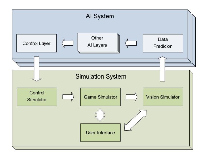
Our software consists of two software subsystems running on two separate computers, vision system and artificial intelligence system.
Basically, the vision system is responsible for handling each input image data frame from the camera and converting the image data into robot's and ball's positions. Then, it sends the information of each frame to the AI system through a socket opened via Local Area Network (LAN).
Meanwhile, the AI system consists of two main parts: vision filtering system and strategy system. Since the image processing in the vision system consumes a significant amount of time and causes delay, we create the filtering system in software procedure to convert delayed raw positions from the vision system into predicted present positions. The strategy system is considered to be the most important part of our system. Its duties are to plan and control our robots. In other words, it is our system's brain.
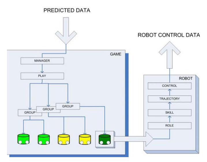
In order to perform an implementation and test each robot function independently, we use layer‐architecture design approach. By means of layer‐architecture, our strategy system is divided into 7 layers including: manager, play, group, role, skill, trajectory, and control layers.
Manager: Manager is analogous to a human soccer team manager. By receiving data such as game score, ball possession, opponent pattern, and referee box signal, manager applies the most suitable play for that moment.
Play: Play provides a real strategy of AI which consists of many game plans. Play will determine the pattern of the game and notify to all robots by assigning robots into 'Group.' Play also selects zone for robots and may issue some commands directly to robot role such as force role to pass the ball to another robot or to shoot the ball.
Group: Group is to implement a group of collaborative robot group to perform a mission such as offensive group and defensive group. One group implementation may be used in many different plays. For instance, there are plays that use the same defensive group but use different offensive group.
Role: Role is implemented as robot behavior which is assigned by 'Play' or 'Group' to control robot to perform a specific action such as manipulating ball inside zone, running to zone, scrambling ball from opponent, getting ball. The 'Role' mechanism first assigns a particular skill to the robot, and then generates the best point for robot action and set another parameter to 'Skill.'
Skill: Skill is a set of basic knowledge for every robot, such as how to move to a point, how to get the ball and shoot. Skill module generates path (a set of points), dribbling and kicking commands that will be processed by varying of trajectory module as selected by 'Skill' module. Each skill has different main idea of generating path for robot. For example, 'get‐ball skill' differs from 'move‐to‐point skill' in many ways. We can study and test each skill independently for the best performance.
Trajectory: Trajectory is a set of methods that generates velocities to control robots. Since each skill focuses on different points, for example, some skills require fast motion while others require accurate positions; different trajectories are created to serve these various needs.
Control: Control is the lowest layer of AI. Its duty is to control the robots' movement. Control receives control data such as velocity, angular velocity from 'Trajectory.' Then Control converts these data into a specified format and sends to each robot via RF device.
3.1 Environment
Our Systems are developed with Microsoft Visual Studio 2005. The vision system is based on C++ due to more running speed requirement. Conversely, since the AI system does not require running speed as much as the vision system, it is based on C# for faster development process.
There are many open source library used in our systems. The vision system utilizes OpenCV, an open source Computer Vision library. The simulator system also uses ODE (Open Dynamic Engine) to simulate a game. Moreover, OpenGL (Open Graphic Library) is used by our systems to produce graphics for user interface.
3.2 Vision
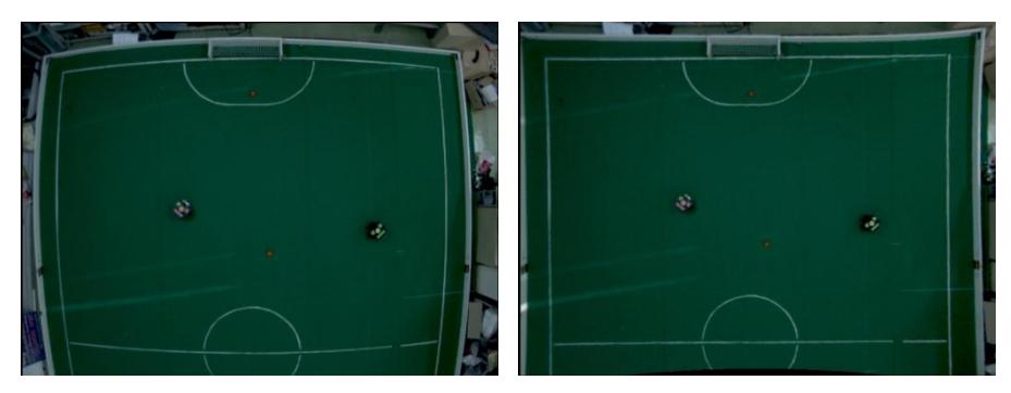
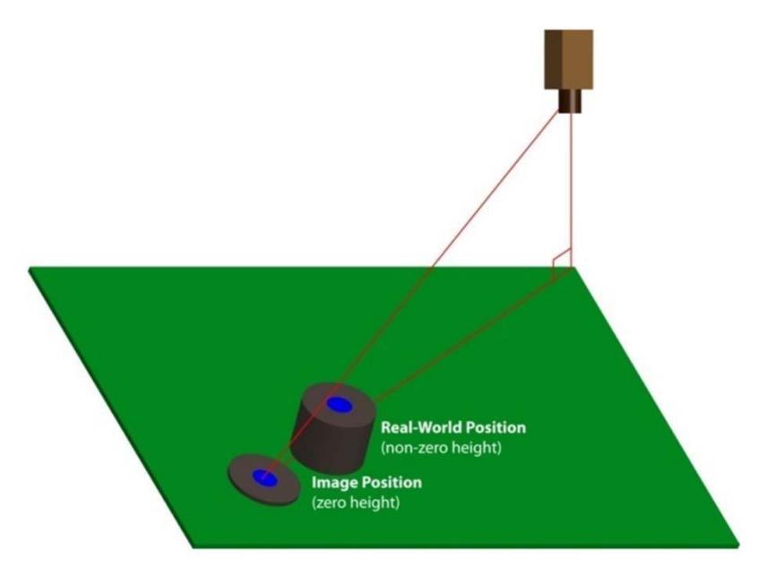
In order to provide all positions and directions of robots and ball in the entire field, our vision system combines two image data from two distinct cameras. Since the raw images contain lens distortion, our system transforms the image to remove distortion and then extracts useful data from images using pattern recognition. Finally it sends the data to client AI computers via the local area network (LAN)
Our vision software's functions can be grouped into 5 subjects: color model, calibration, segmentation, pattern recognition, and networking.
3.2.1 Color Model
There are 3 color models related to our vision system. First, our camera received image data from the camera in YUV Color Model. Next, we have to convert it to RGB Model in order to display it on the monitor. As HSV Model can describe perceptual color relationships more accurately than RGB, we convert the RGB image to HSV one for segmentation process.
3.2.2 Calibration
Our vision software requires some camera parameters in order to process the data received from the camera. These parameters are grouped into intrinsic and extrinsic parameters.
First, the intrinsic or internal parameters are the data depending on the camera and lens. There are five intrinsic parameters:
- f Effective focal length of the pin‐hole camera,
- k 1st order radial lens distortion coefficient,
- Cx, Cy Coordinates of center of radial lens distortion and the piercing point of the camera coordinate frame's Z axis with the camera's sensor plane,
- Sx Scaling factor to account for any uncertainty in the frame grabber's re‐sampling of the horizontal scan line.
Second, the extrinsic or external parameters are based on the position of the camera. These parameters are used to convert the world coordinate to the image coordinate. There are six parameters:
- Tx, Ty, Tz Translational components for the transform between the world and camera coordinate frames,
- Rx, Ry, Rz Rotation angles for the transform between the world and camera coordinate frames.
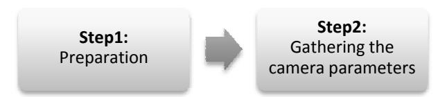
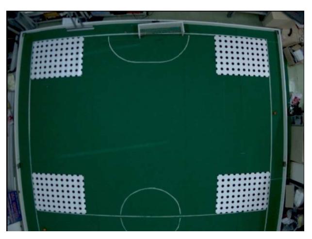
The calibrate process can be separated into 2 steps.
3.2.3 Segmentation
Segmentation is a process of partitioning an image into multiple segments. The objective is to simplify or change the original image into another representation which is more meaningful or easier to analyze.
The vision software achieves its goal by starting with scanning the entire original image to collect a position that its color is in the software's color lookup table. These positions tend to be either robots or balls. Then, the software will use the collected position to decide that which section in the image should be undistorted. This makes our system process the image faster than undistorting the whole image. Finally the software will intensively scan each segment again in order to extract the exact position of the objects.
To initialize the process, we need to set the color range in the color lookup table and the criterion of the objects. First for the color lookup table, we use HSV color model to specify the range of each color. Second, there are three considered object criteria: color, blob size, and eigenvector. Blue and yellow are used for identifying the robots' team while orange is used for the ball and other colors are used for identifying the robots' number. The blob size is the range of pixels indicating the blob we interested. For each extracted data, we have a confidence value to indicate how confident the data is. The closer the blob size gets to the criteria, the better confidence value it gets. If the software finds a blob whose size is out of range, it will conclude that the blob is a noise and can be discarded. The last part, eigenvector is used for determining the expansion of blob. As we are interested only in the circle and long rectangle blobs, a blob with longest expansion of eigenvector is a long rectangle; otherwise, it is a circle.
After finishing the initialization, the program extracts a blob that matches the criteria using the flood fill algorithm for both rough and thorough scans. This process is critical and time‐consuming. The extracted blobs are further used to recognize the objects.
3.2.4 Pattern Recognition
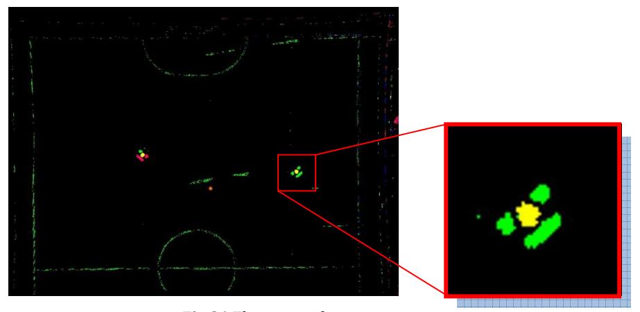
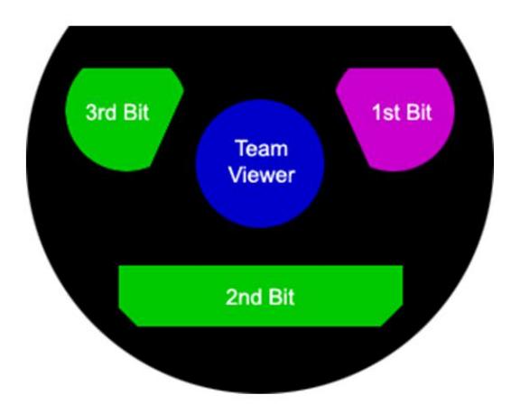
The vision software recognizes only our robot's head. It uses each blob for identifying the number of our robots. They are represented in binary format. One blob represents one bit. We use a green blob for representing bit 0, and pink for bit 1. For example, in the figure, the number of this robot is 0012 in binary format or 110 in decimal. For opponent robots, the software just finds a center circle blob and assumes that there is no noise blob of which color is the same as the opponent's.
3.2.5 Networking
The vision system, working as a server for AI system clients, will open the socket for receiving connection requests from clients. Moreover, this socket also sends the data packets via the local area network (LAN) using TCP protocol which guarantees reliability and packet ordering.
The software sends the robots' and balls' data (including position, direction, and confidence level) to the client AI computer every frame after finishing processing the captured image. Hence, the transfer rate is equal to the camera frame rate, approximately 60 frames per second.
3.3 Motion Control
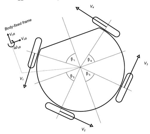
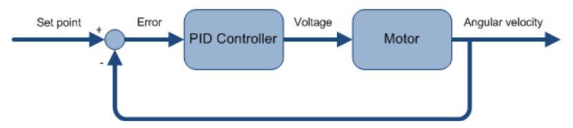
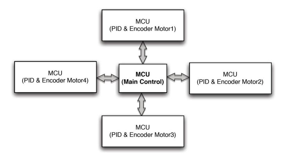
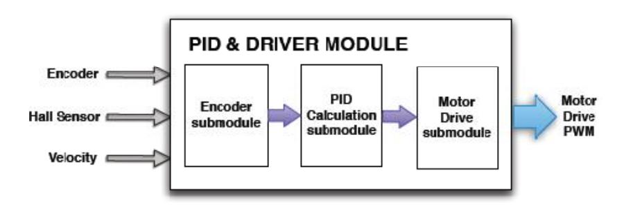
The velocity and the direction of the robot depend on the velocities of all driving motors (V1, V2, V3, V4). It is significant to control the velocities of all driving motors to meet the velocity and direction requested from AI system. The AI system command contains velocities in x-y dimension, VxB, VyB, and an angular velocity of the robot, ωzB, on a body-fixed frame.
3.3.1 Closedloop Motion Control system
3.4 Kick Control
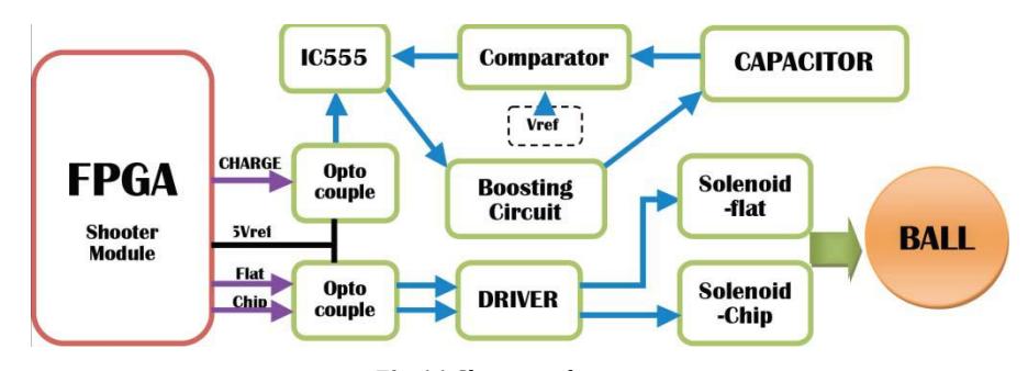
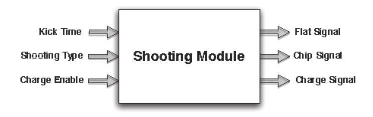
There are two modes for kick control command: flat kick and chip kick. A kick power level for each mode ranges from 0‐255. Once a mode for shooting is selected and a kick power level is calculated, the AI system sends the kicking command to the robot. After getting IGBT gate opening time, kicking mode and charging command from AI system, the main processor in the robot sends these parameters to the Shooting module. IGBT gate opening time indicates pulse generating time to IGBT gate to enable current flow from the capacitor to the solenoid. Kicking mode determines which solenoid, either flat kick solenoid or chip kick solenoid, is the destination of the generated pulse signal. Charging command switches the MOSFET to boost circuit in order to start charging the capacitor.
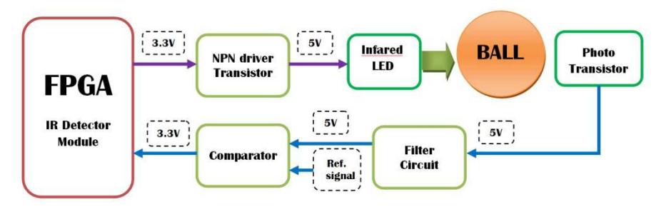
AI system can choose between 2 kick modes: wait kick mode and forced kick mode. In the wait kick mode, kicking occurs only when the ball is detected by ball IR detector. On the other hand, in the force kick mode, kicking takes place immediately.
3.5 Dribbler Control
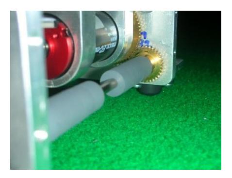
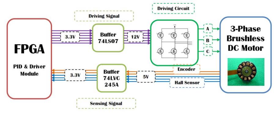
Dribble Module is the open loop control system for driving the dribble motor. Because the dribble motor is a BLDC motor, it is important to apply PWM signal to the driving circuit using the correct phase determined by the hall sensor signals. Closed‐loop Control system is not necessary for this application because the aim is only to hold the ball, not controlling the angular velocity of the motor. A fixed speed for rotation is enough to hold the ball near the robot. Dribble Module provides four levels of angular velocity to AI system which, in turn, chooses the level of angular velocity and the direction of rotating, and then sends that command to the robot.
3.6 Wireless Communication Control
AI System uses radio frequency to broadcast commands to the robots. The commands of all robots are packaged in one serial data chunk. RF Receiver Module in the FPGA accesses the buffer in the RF device to get the package sent from AI and, then, sends them to Main processor module. Because the package contains all commands for not just one but all robots, each robot must choose the packet in the whole package to obtain its own command. The Vision Number of Packet field in the 25th and 26th bytes of the package is used to select the robot for that packet. For example, the vision number of packet0 is 2. It means that the packet0 belongs to robot number 2. Before sending the package to the main processor module, the CRC Checker submodule in RF Receive Module also detects communication errors of receiving package.
Format description of communication data
| Field | Size (bit) | Description |
|---|---|---|
| is_chip | 1 | Indicate which kick to perform: flat kick or chip kick |
| send_back | 1 | Request the data from the robot but still unused yet |
| sign_vx | 1 | Indicate the sign of vx |
| sign_vy | 1 | Indicate the sign of vy |
| sign_wz | 1 | Indicate the sign of wz |
| forcekick | 1 | Indicate kick mode: wait kick or force kick |
| drib_speed | 2 | Control the angular velocity of the dribbler motor between four levels |
| vx | 8 | Value of the velocity command in x axis |
| vy | 8 | Value of the velocity command in y axis |
| wz | 8 | Value of the angular velocity command in z direction |
| kick_time | 8 | Indicates pulse generating time to IGBT gate |
| vision number of packet | 3 | Match the robot to that packet |
| drib_dir | 1 | Indicate the direction of dribble motor rotation |
3.7 Simulator
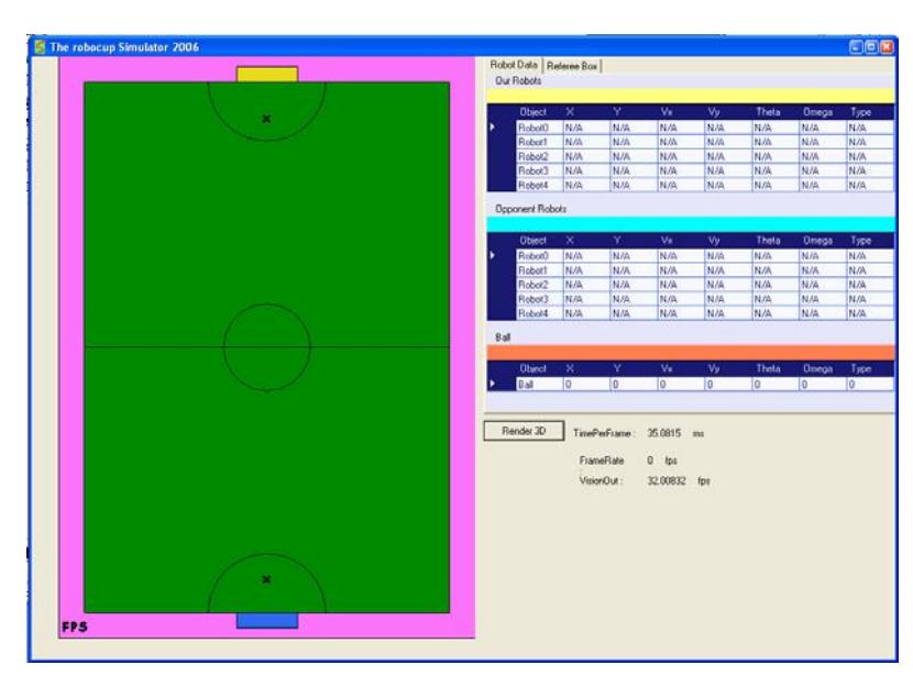
In the early phase of play and strategy testing, sometimes it takes too excessive cost and overhead time to setup the testing environment. Therefore, testing plays on a simulator will let the developer focus on the test rather than setting up testing environment. After the play performing well on the simulation, we proceed to test it in the real environment.
3.8 Behavior
Our behavior system manages robot strategies and actions during gameplay.
3.8.1 Path Planning and Collision Avoidance
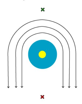
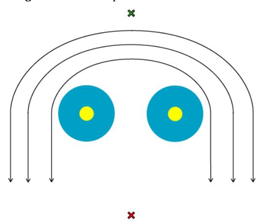
Our path planning system is based on the Force Field approach. The goal of the system is to find a collision‐free path from the start position to the target position. In order to avoid collision, the obstacles such as robots and walls are taken into the system as repulsive forces. A ball is sometimes considered as an obstacle when the robot performs ball avoidance. In addition, the attractive force pointed toward the goal position is summed up to attract the robot. The path planning system obtains the desired path by calculating a resultant force along the path. However, there is a problem with this approach. It is a local minimum which is the point that the resultant force approaches zero and traps the robot before reaching its goal position. In order to avoid a local minimum, we use a pattern of force field around the robot preventing the goal point. Additionally, when there are several obstructive robots, they are grouped as obstacle and a similar pattern of force field is then applied.
Currently, there are many parameters that are tuned in a brute‐force manner. However, our system provides a collision‐free path that the robot can follow properly without a local minimum problem.
3.8.2 Passing
When a robot passes the ball to another robot, there are many factors to be considered. For examples, are there any opponent's robots around, or is our teammate's robot ready to receive the ball? If the certain conditions are met, robot will perform the passing. Otherwise, our AI system will consider alternative options.
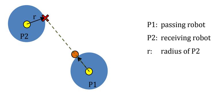
One of the easy but effective ways to calculate the position to pass the ball is to use the position of the receiver's robot plus the offset of the radius of the robot in the direction of the receiving robot. A red cross indicates the receiving position.
3.8.3 Kicking
Since our robot has two types of kicking: flat‐kick and chip‐kick, we have to consider which type to be performed. Basically, we use the flat‐kick when there is no blocking opponent's robot or if we want to kick the ball with a very high speed, especially for shooting. Conversely, chip‐kick is used when the shooting direction is blocked by one of opponent's robots or when the speed of the travelling ball is not required.
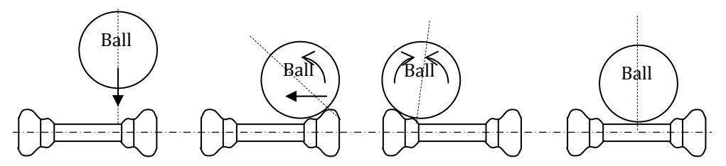
Another kicking technique is to turn on the dribbler and the kicking mechanism simultaneously in order to center the ball. As a result, the direction of the ball is more accurate to the desired position than without the dribbling.
The main parameter that can be changed for each kick is the kick power. For flat‐kick, kick power determines how fast the ball will travel while for chip‐kick, kick power determines how far or how high the ball will be after being kicked.
3.8.4 Dribbling
In our program, there is no specific skill for just dribbling, but we will do it along with other skills. To dribble is just to turn on the dribbler and move to the desired direction. One thing to be kept in mind is that the allowable robot speed depends on the quality of the dribbler. If the dribbler works very well, robot can move faster. Otherwise, robot might have to slow down its speed in order to avoid losing the possession of the ball. Using the dribble near team's defense area is also risky. Since the dribble spins the ball backward, if the robot loses the ball, it is highly probable that the ball will move toward into our own team's goal.
Even though the main use of dribbler is to control the ball, its usage can be various. These include taking the ball from opponents, controlling the ball while dribbling it for a short distance, or even guiding the direction of the ball before being kicked.
3.8.5 Roles & Positioning
Adapted from traditional football plays, which have four major players' roles: Goalkeepers, Defenders, Midfielders and Attackers; our robots have three major roles: Goalkeeper, Defenders and Attackers. Due to less number of players in the pitch, including Midfielder Robots would add unnecessary complexity in our system since attacker, defender and goalkeeper are sufficient for strategy.
Each robot's role will be assigned manually at the beginning of the game. One reason that we do not allow robots to switch its role during the game is that the switching condition is very subtle. As a sample situation, the attacker is about to get the ball from the opponent, however, at the same time, there is a small gap for the opponent to shoot the ball to our goal. That attacker robot might move back to narrow down the gap. This could mean that we have missed a good chance to steal the ball from the opponent.
The main job for attackers is trying to possess the ball and shoot the ball into the opponent's goal. One of the attackers will try to get the ball while the other two will move around and be ready to receive the ball if passing technique is being used.
The main job for defender and goalkeeper is trying to prevent the ball from entering into our goal. The defender will closely cooperate with the goalkeeper in order to prevent the ball from entering our goal.
3.8.6 Strategies
In the world of Traditional Football, there is a well‐known strategy: "attacking is the best defense." Our team strongly agrees to that theory. Accordingly, we prefer to use 1‐1‐3 formation. In other words, there are one goalkeeper, one defender and three attackers. The goalkeeper works cooperatively with the other defender to narrow down the shooting angle, clear the ball away from risky area or do any other things that will ensure our goal's safety By the way, the attackers mainly works cooperatively to score a goal. However, if the opponent possesses the ball, our attackers will help the goalkeeper and defender by tackling, stealing the ball, or marking enemy robots.
We have many different plays that match various situations. For instance, we have plays for offensive and defensive corner kicks, direct free kicks, indirect free kicks, normal play, etc. There are several plays that can be used in the same situation. The decision whether to perform which playing pattern is highly related to its effectiveness. There is a parameter to indicate the effectiveness for each play. Our play selector has more chance to select higher valued play. These effectiveness values are manually edited from previously recorded statistics. As a future development, we plan to record the game stats so that these parameters can be automatically adjusted after each game or even during the game.
4) Conclusions
After many years of research and development, we have faced various kinds of problems and also found some good solutions for those. The experience we gained results in the improvement of our team in the competitions at both national and international levels. Nevertheless, we will keep developing our system for even better performance.
References
- AVT Stingray F046B/C Fiber DataSheet. [Online] AlliedVisionTec. http://www.g4.com.tw/web/file/product/demo/Stingray_DataSheet_F046BC_fiber_V 1.0.0_en.pdf.
- Altium Nexar TSK51. [Online] http://www.keil.com/dd/chip/3730.htm.
- [Online] http://robocup.mi.fu-berlin.de/buch/omnidrive.pdf.
- A Versatile Camera Calibration Technique for HighAccuracy 3D Machine Vision Metrology Using OfftheShelf TV Cameras and Lenses. Roger, Tsai Y., IEEE Journal of Robotics and Automation, Vol. RA-3, No. 4, pp. 323-344, August 1987.
- An Efficient and Accurate Camera Calibration Technique for 3D Machine Vision. Roger, Tsai Y., Proceedings of IEEE Conference on Computer Vision and Pattern Recognition. pp. 364-374, 1986.
- Dias, Paulo. Tsai Camera Calibration. [Online] 11 5, 2003. http://homepages.inf.ed.ac.uk/rbf/CVonline/LOCAL_COPIES/DIAS1/.
- Davis, James. tclcalib - A tool for camera calibration. [Online] http://www.soe.ucsc.edu/~davis/projects/tclcalib/.
- Eigenvalue, eigenvector and eigenspace. Wikipedia, the free encyclopedia. [Online] http://en.wikipedia.org/wiki/Eigenvector.
- Flood fill. Wikipedia, the free encyclopedia. [Online] http://en.wikipedia.org/wiki/Flood_fill.
- Accuracy Improvement of OmniDirectional Mobile Robot using Gyroscope and Acelerometers. Sirichai Pornsarayouth. M.Eng. Dissertation, Chulalongkorn University, Bangkok, Thailand, 2008.
- FPGA Implementation of ClosedLoop Control System for Small Scale Robot. Wei Zhao, Byung Hwa Kim, Amy C. Larson and Richard M. Voyles. Proceedings of the International Conference on Advanced Robotics, pp. 70-77, 2005.