RoboDragons 2009 Extended Team Description
Hiroki Achiwa, Junya Maeno, Junya Tamaki, Saori Suzuki, Tatsuya Moribayasi, Kazuhito Murakami, Tadashi Naruse
Aichi Prefectural University, Nagakute-cho, Aichi, 480-1198 JAPAN
Abstract The RoboDragons team of Aichi Prefectural University has been doing its activity for 11 years this year. At first, the team started as a joint team with Chubu University in 1999. The name of the team at the time was Owaribito. In 2002, however, we newly started our team as the team consisting of people of Aichi Prefectural University and our team was renamed RoboDragons. In 2004 and 2005, we made a joint team with Carnegie-Mellon University to brush up the robot system. The name of the team was CMRoboDragons. Meanwhile, we won the 1st place 4 times in the Japan open and won, in the RoboCup World Competition, the 3rd place in 2007 and the 4th place in 2004 and 2005.
Our current robots are the fourth generation ones in our Labs and the soccer software is an improved one which was originally developed by CMU during 2004 and 2005 when we had the joint team. Many technical elements of the robots are introduced the technology developed by the strong teams such as Cornell University, Free University of Berlin, Carnegie-Mellon University and so on, however, the solenoid driving circuit which realizes the powerful kicking is our original one. The soccer software is improved for our purpose by implementing the various strategies and the cooperative play skills such as 1-2-3 shoot.
In this paper, we describe the RoboDragons system in detail.
1 Introduction
The RoboDragons team of Aichi Prefectural University has been doing its activity for 11 years this year. At first, the team started as a joint team with Chubu University in 1999. The name of the team at the time was Owaribito. In 2002, however, we newly started our team as the team consisting of people of Aichi Prefectural University1 and our team was renamed RoboDragons. In 2004 and 2005, we made a joint team with Carnegie-Mellon University to brush up the robot system. The name of the team was CMRoboDragons. Meanwhile, we won the 1st place 4 times in the Japan open and won, in the RoboCup World Competition, the 3rd place in 2007 and the 4th place in 2004 and 2005.
Our current robots are the fourth generation ones in our Labs and the soccer software is an improved one which was originally developed by CMU during 2004 and 2005 when we had the joint team. Many technical elements of the robots are introduced the technology developed by the strong teams such as Cornell University, Free University of Berlin, Carnegie-Mellon University and so on, however, the solenoid driving circuit which realizes the powerful kicking is our original one. The soccer software is improved for our purpose by implementing the various strategies and the cooperative play skills such as 1-2-3 shoot.
In this paper, we describe the RoboDragons system in detail.
1 The reason is that students of both universities had grown up to be able to develop their robot system theirselves in each university.
2 RoboDragons Team Members
The members and their roles of RoboDragons 2009 are as follows,
- – Junya Maeno(Strategy and Tactics, Team Leader)
- – Hiroki Achiwa(Vision and Mechanics)
- – Junya Tamaki(System Design)
- – Saori Suzuki(Tactics)
- – Tatsuya Moribayashi(Vision)
- – Kazuhito Murakami(Supervisor)
- – Tadashi Naruse(Supervisor)
3 RoboDragons system overview
In this section, we give an overview of the RoboDragons system.
RoboDragons system consists of 5 robots, a host computer, cameras, a video capture board and a communication device(modem). Table 1 shows the summary of the system.
Robots Products of SMATS Inc.
Table 1. RoboDragons system overview
| Robots | Products of SMATS Inc. |
|---|---|
| Host Computer | |
| CPU | Athlon64 X2 4200+ |
| Memory | 512MB |
| OS | Debian GNU/Linux |
| Language | C++ |
| Compiler | gcc version3.3 |
| Cameras | |
| Body | Panasonic DVR-310 |
| Lens | RAYNOX HD-5050PRO |
| Video Capture Board Philips SAA7133 based | |
| Modem | Futaba FRH-SD03T |
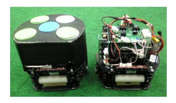
Figure 1 shows an outward of the robot with and without the robot cover. Each robot has 4 omni-wheels each of which is driven by a DC motor with an encoder, kicking devices which realize a straight kick and a chip-kick, a dribbling device, and computer boards that controls the robot. Detailed description of the robot is given in the next section.
4 Robots
In this section, we discuss our robots in detail.
4.1 Robot hardware
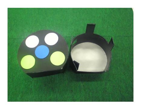
Dimensions of robot The robot can be packed in the cylinder with dimensions of 145 mm height and 178 mm diameter. To protect the internal circuit boards and mechanical devices, the robot is covered by the cardboard shown in figure 3. To reinforce the cardboard, the plastic sheet with 1.5 mm thickness is glued on the cardboard.
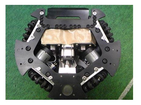
Drive unit The robot has 4 wheels each of which is drived by a DC motor. The wheel is so called an omni-wheel. Figure 4 shows the omni-wheels attached to the robot.
The DC motor driving the omni-wheel is Maxon's "RE-max 24" with encoder unit. The source voltage of the motor is 15 V . The motor also has a pinion gear with 12 teeth and the omni-wheel has a gear with 95 teeth so that the reduction ratio is 1 : 7.92. The diameter of the omni-wheel is 60 mm and the omni-wheel has 15 small tires in circumference. The diameter of the small tire is 13 mm.

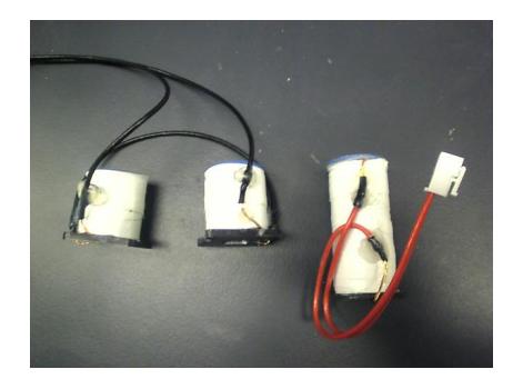
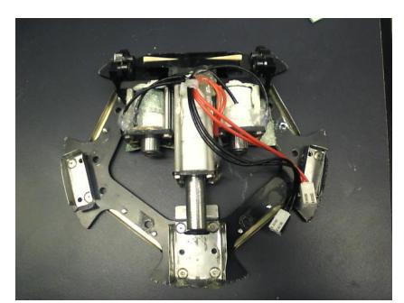
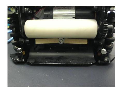
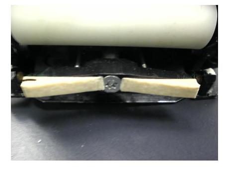
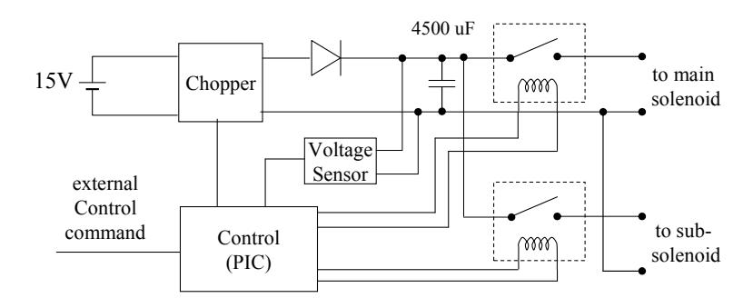
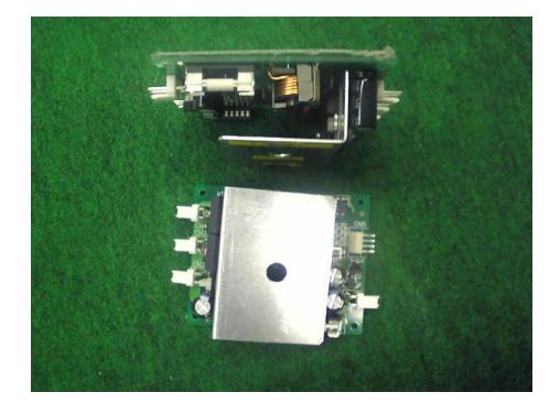
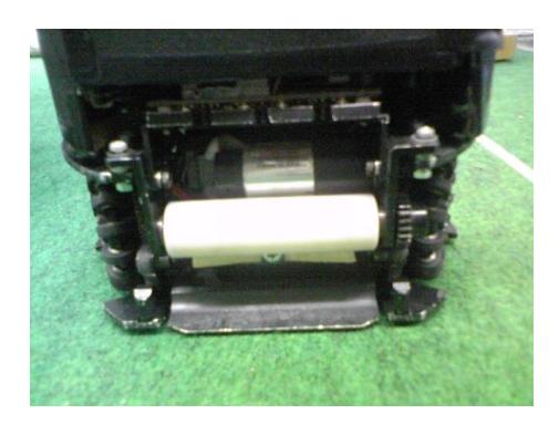
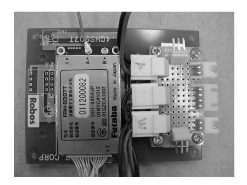
4.2 Software on robots
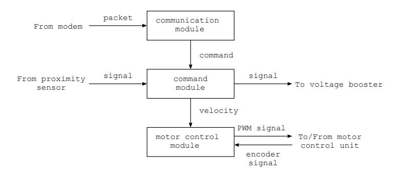
Here we describe the software on the robot. The program is written by the C programming language. A tiny real time monitor is used. This monitor program is offered by the SMATS Inc. It provides multi-process environment.
Robot control program consists of three modules each of which is invoked as a process. They are communication, command and motor control modules. Figure 16 shows a data/signal flow among modules and peripheral units.
5 Vision system
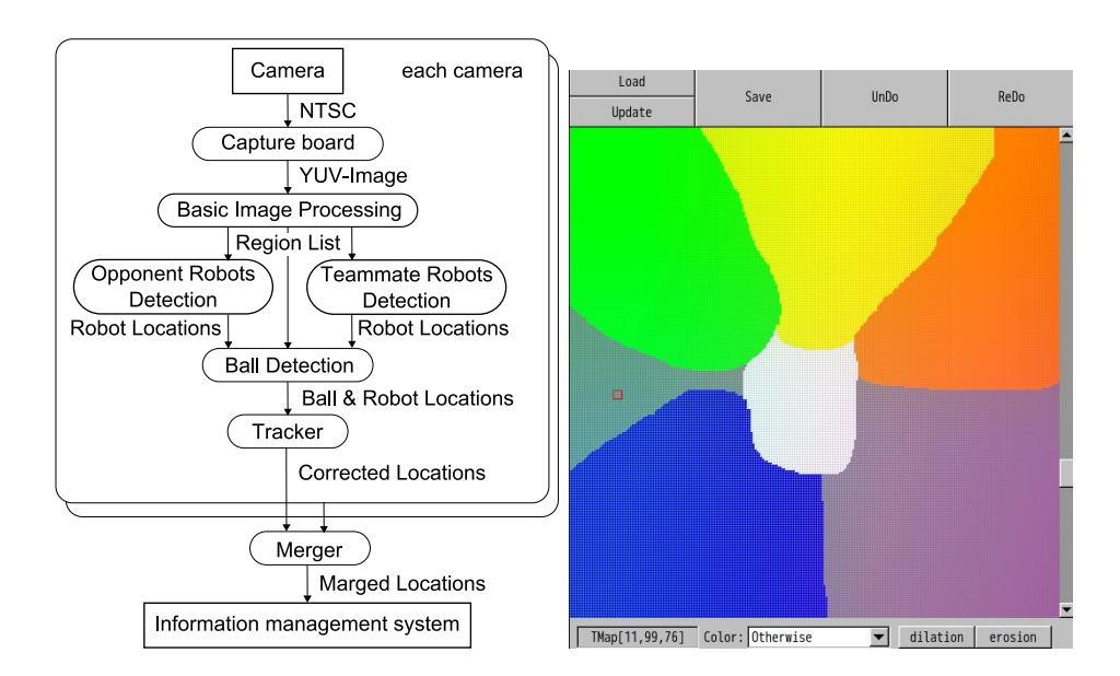
The vision system consists of the calibration system and the image processing system. The calibration system calibrates a coordinate system and a color system before a game starts. The image processing system detects the positions of the ball and robots from the images given by two cameras set at over the field, and then merges the positions. The merging process is necessary since there is overlapped area in two camera images. The merged positions are sent to the world system(information management system). Figure 18 shows the dataflow of the main modules of our vision system. This system have been developed based on the CMVision(Version2.1a) system of Carnegie Mellon University.
In this section, 5.1 describes the calibration system. 5.2 5.6 describe the detection process for given images, and 5.7 describes the merge process of positions. See section 3 for the hardware description of the cameras and the capture board.
5.1 calibration System
Color calibration In the image processing, we have to extract the ball and the teammate and opponent robots from the captured images which are YUV images. The ball is characterized as an orange area and the robots are characterized by a team marker and sub-markers. The team marker is characterized as a yellow or blue area and submarkers are characterized as light green, light pink, cyan and white area. These colours are suitably distinguished.
To do so, we use a colour lookup table. The lookup table is a 3 dimensional array corresponding to Y, U, V axes whose resolutions are 16, 256 and 256 levels respectively. The element of the array shows colour id number. We give each element of the array the suitable colour id number manually using the paint tool. An example is shown in figure 19. It shows a U-V plane. Y value can be changed by the scroll bar at right side. There are several regions in Fig. 19. A region corresponds to some colour. Using the lookup table, the captured YUV images are classified into regions having colour id numbers.
Coordinate calibration We obtain the camera model used for the projective transformation that converts the image coordinates into world coordinates.
First, we put calibration markers on the designated positions on the filed. These positions are the positions in the world coordinate. Then, we get the field images and obtain the coordinates of markers on the images. Finally, camera parameters are updated manually by using world coordinate and image coordinate and initial parameters. These parameters are obtained by the conjugate gradient method of Fletcher-Reeves to minimize the error of world coordinate and logical coordinate. We use the GNU Scientific Library to calculate the conjugate gradient method. The camera model is generated using the parameters obtained here.
Other Configurations We make a mask image to avoid the miss detection by objects existing at the outside of the field. The image is made using the dedicated paint tool. The size of the image is the same as the size of the captured image. The masked area is excluded from the image processing.
A color histogram around the team marker of opponent robot is made in advance. This is used to improve the detection accuracy of opponent robots.
5.2 Basic Image Processing
The capture board control program is written by using the Video4Linux(V4L). The ring buffer is made on the memory of the capture board. This makes possible to get the latest image when the image processing program attempts to get the image.
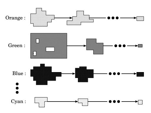
In the basic image processing in Fig. 18, the captured images are classified into regions having colour id numbers by using the lookup table given in section 5.1. To the resulting images, labeling processing is done. For each colour id number, the labeled components with the same id are listed in descending order of the size of the area as shown in figure 20. We call this list a RegionList.
5.3 Opponent Robots Detection
There are two common processes for object detection. First, we use confidence value. The confidence value shows how the detected object is reliable as the object itself. The value ranges from 0 (least reliable) to 1 (most reliable). Second, the transformation from image coordinates to world coordinates is calculated through the camera model obtained in the section 5.1.
Operators can give parameters needed to detect the robots through the GUI. The parameters are a team colour, a robot model, a number of robots and so on. The robot model is a configuration of submarkers. In our robot, 4 circular submarkers are arranged like the feathers of a butterfly. So we call the robot model a butterfly model. (See Fig. 1.) Use of robot model helps to increase the reliability (confidence value) of the detected robots. For the opponent team, if it doesn't use a butterfly model, only team maker is used to detect the robots. Namely, in the RegionList for blue or yellow colour, regions with designated width, height and area are chosen as the candidates of opponent robots, and the color histogram of region around the team marker given in section 5.1 and that of a candidate region is compared. If these histograms are similar, then the candidated region is remained as a team marker region and the confidence value is calculated. The confidence value is 1 if the area A of the region is between $TH_{min}$ and $TH_{max}$ , otherwise, it decreases as the $A-TH_{max}$ increases or $TH_{min} - A$ increases. These threshold values are decided by the experiment before a game starts.
The opponent robots are detected as top N regions that have high confidence values, where N is a number of opponent robots (usually 5). At the same time robot positions (world coordinates) are computed as a gravity center of the region.
Robot ID is decided by using the GreedyMatching algorithm. This algorithm computes the Euclidean distance between the detected robot position and the positions of all robots 1 frame ago and decides the ID of the detected robot as the ID of the robot in the previous frame that has the minimal distance.
5.4 Teammate Robots Detection
For teammate robots, the detection is done as follows. First, choose the candidates of team marker regions from the RegionList and compute their confidence value.
Since the teammate robots use the butterfly model, the candidates of submarker regions are selected from the RegionList according to the using submarker colours (white, light green, light pink and cyan). The confidence value and the position of each candidate submarker region is computed.
For each candidate of team colour region, the submarker candidate regions that exist within the circle whose center and radius are center position of team colour region and robot size (namely 9 cm) are searched. If 4 submarker candidates are detected within the circle, the circular region is teammate robot and submarkers are ordered and numbered as shown in figure 21. Fig. 21 shows the positions of a template pattern. Detected pattern is a rotated pattern of the template pattern. The rotation center is an origin of x-y axes. This rotation angle gives the direction of the robot. To reduce the detection error, the rotation angles of all submarkers are computed and their mean value becomes the rotation angle of the robot.
The position of the teammate robot is computed using the team marker and the submarkers. Confidence value is also computed using these markers. The confidence value is 1 if the error E of the detected submarker positions from the robot model is less than T H, otherwise, it decreases as the E − TH increases. The threshold value is decided by the experiment before a game starts.
The ID number of a robot can be decided using table 2. We use the light green and light pink submarkers. When 4 submarkers are numbered from 0 to 3 and colours are numbered from 0 to 3 as shown in Fig. 21, the colours of ordered submarkers give the ID number of robot as shown in table 2.
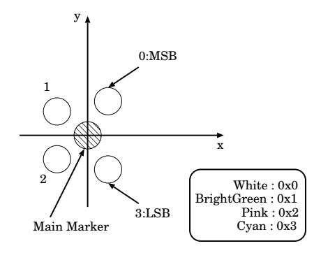
Table 2. ID table
| Robot ID Color Pattern | |
|---|---|
| 0 | 0x1111 |
| 1 | 0x1112 |
| 2 | 0x1121 |
| 3 | 0x1122 |
| 4 | 0x1211 |
5.5 Ball Detection
In the detection of the ball, for each candidate of the ball region in the Region-List for orange, the width, height and area size of each region is checked and the confidence value is calculated. Then, the best matched region is selected as the ball region. The confidence value is calculated in the same way as that of opponent robots.
However, orange regions are often detected around the boundary between the yellow marker and light pink submarkers. For such regions, the confidence value is lowered.
5.6 Tracker
The position data of detected objects (robots and a ball) may have an error. Therefore, we use the Kalman filter to compensate the positions and velocities of the objects. For robot objects, the directions and angular velocities are compensated too.
Assuming the linear uniform motions for objects5 , the Kalman filter equations are computed. We assumed that the process noise and the observation noise are Gaussian white noise. Thus, the position data at the current frame are compensated.
If position data are failed to detect at the current frame, the estimated position data from the past position data by the Kalman filter are used.
5 For a short time span, this assumption is reasonable.
5.7 Merger
Multiple cameras (in our case, 2 cameras) cover the whole field for objects detection. There are overlapped areas on the field that are covered by 2 or more cameras. When there are objects in such an overlapped area, they are detected from 2 or more images of the cameras. In such case, we have to select the suitable one from the several candidates of one object. The merger does this.
Basic idea is to select the candidate of object with highest confidence value. For the teammate robots, the submarkers give enough information to decide robot ID. So, it is easy to select the object with highest confidence value. For the opponent robots, the GreedyMatching algorithm is used to decide the robot IDs again for all robots detected in all images. Then, the robot with highest confidence value is selected if there are robots with the same ID.
The merged ID data are sent to the world system.
6 World system
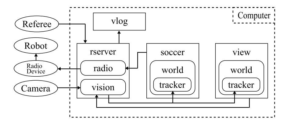
The world system is an information management system used with the soccer system (strategy system) and the view system (GUI system). The world system processes the data to be used in the soccer system and the view system based on the data obtained from the rserver system. In this section, we explain the data used in the world system, the view system and the simulator system.
6.1 World system information
Location information
The world system obtains the location data of each robot and ball from the vision system and the tracker system, and then estimates the location data at 5 frame later based on the model of linear motion. Consequently, the world system has three location data from (1)the vision system, (2)the tracker system, and (3)the world system.
Obstacle information
The obstacle information includes the areas of opponent and own team's defense, the area of field data, opponent and teammate robots and ball. These data are used to avoid the collision.
6.2 View system
The view system displays the game status, internal data or the parameters of the system for the user. This system partially utilizes CMDragons' GUI system [1].
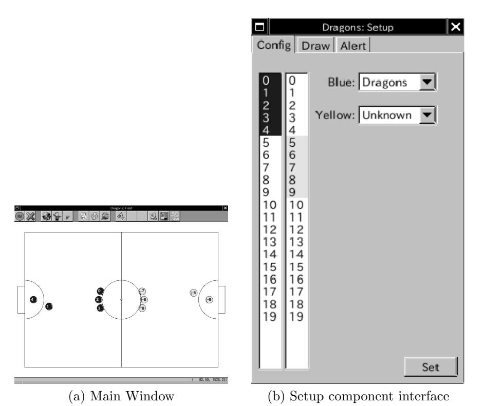
Figure.22(a) shows the "Main Window" of the view system. The "Main Window" displays the field image on the center of it and the buttons to start each component system. Figure.22(b) shows the "Setup component". We explain some of typical components as the example.
1. Setup component
Here, it sets up fundamental information. It can change the number of the robot, and display velocities of robots or ball on the "Main Window".
2. Referee Box component
This component operates the robot by generating referee signals by the user. This is used for the check of robots.
3. Operating check component
This component sends the command to the robots. For example, this is used for the operation of the moving from the edge of the field to an other one.
6.3 Simulator
In RoboDraons system, the simulator system is included as an alternative of the rserver. By using this simulator, we can operate our system in near real environment.
The simulator system obtains some data which is robots and ball location and velocity, and game state. According to the robot operation data from the soccer system, it processes robots' movement, kicking and collision of robots and ball, and then updates robots and ball location and velocity. Furthermore, according to the referee command from the view system, it updates game state. Moreover it can change the location and velocity of robots and ball by operating from the view system.
Generating data is sent to the world system same as the rserver.
7 Soccer system
The soccer system selects a strategy based on the information given by the world system, and assigns the roles in order to achieve the strategy to each teammate robot. Each robot receives the operation command by radio. In this section, we describe our soccer system.
7.1 Strategy selection
Strategy selection index
The soccer system selects a strategy by the basis of indexes shown in Table.3. A strategy is composed of some indexes. Each index is generated by the world system.
Play file
One play file shows one strategy. It is described by the text on our system. A play file includes strategy name, the condition that the strategy is selected, the condition to abort it, the condition to achieve it, necessary number of robots, and roles(skills) for each robot and priority of each role.
Play book file
In play book file, play files' name and its priority are described. Only the soccer system can select play files described in play book file.
Strategy selection
The soccer system selects play files described in play book file based on the strategy selection indexes. In many cases, only one play file is selected. When some play files are selected, then high-priority one is selected.
Assignment of role of each robot
Our system calculates costs used for assignment of role of each robot. In many cases, the cost is distance between current location of the robot and target location of the role. The combination of roles and each robot which minimizes total of costs is selected. Only the goalie is excepted because it must be selected previously.
Table 3. strategy decision index
| Index Name |
|---|
| Game on |
| Game off |
| Our team KickOff |
| Our team Indirect FreeKick |
| Our team Direct FreeKick |
| Our team Penalty Kick |
| Opponent team KickOff |
| Opponent team Indirect FreeKick |
| Opponent team Direct FreeKick |
| Opponent team Penalty Kick |
| Opponent team Penalty Kick |
| Our team attacking |
| Our team defending |
| Loose ball |
| Ball is in Opponent side |
| Ball is in Our side |
| Ball is in around center |
| Ball is near Opponent goal |
| Ball is away from Opponent goal |
| Ball is near Our corner |
| Ball is near Opponent corner |
| Our team winning |
| Our team losing |
| Our team winning big |
| Our team losing big |
7.2 Role and skill
Role described in play files is composed of some skills. One skill is one class in our system, and it has function for calculating target location and velocity of the robot based on the data from the world system. Then, the soccer system obtains them from skills, and sent target location and velocity, and obstacle data to the path generation. The following shows some of the skills often used in the game.
1. Goalie skill
  [purpose] to defend our goal
  [number of robots] 1
  [algorithm]
     if(opponent PenaltyKick)
          then move to the location on the extended line of opponent
               kicker direction
     else if(the ball is in our DefenseArea)
          then move to behind of the ball and push it out to the
               outside of DefenseArea
     else if(the ball is in front of the robot)
          then chip-kick the ball
     else if(the ball moves to the goal)
              if(goalie can move to intercept point earlier
                 than any other teammates)
                  then intercept the ball
              else
                  then defend our goal with defenders cooperatively
     else
          then defend our goal with defenders cooperatively
2. Defender skill
  [purpose] to defend our goal
  [number of robots] 1˜2
  [algorithm]
     if(the ball is in our DefenseArea)
          then wait around our DefenseArea
     else if(the ball is in front of the robot)
          if(opponent robot exists around the line which is
             connected from the defender to the ball)
              then chip-kick the ball
          else
              then straight-kick the ball
     else if(the ball moves to our goal)
          if(defender can move to intercept point earlier
             than any other teammates)
              then intercept the ball
          else
              then defend our goal with other teammates
else
          then defend our goal with other teammates
3. Marking skill
  [purpose] to block shoots and passes
  [number of robots] 1˜2
  [algorithm]
     Let X be the opponent robot which is nearest to the ball
     if(opponent corner kick)
          then move between X and opponent robot which is nearest to
               our goal
     else if(opponent throw-in)
          then move between opponent robot which is nearest to
               our goal and center of our goal
     else
          then move on the line connected from X to the ball
4. Attacker skill
  [purpose] to take the ball, dribble, shoot and pass
  [number of robots] 1˜4
  [algorithm]
     if(not keep the ball AND other Attackers do not keep the ball)
          then move to the ball
     else if(keep the ball)
          if(opponents also keep the ball)
              then spin around to flip the ball
          else if(opponents is far from the ball)
              if(the shoot course is open)
                  then shoot
              else if(opponent robot dose not stand between self and
                      teammates)
                      then pass
              else if(the distance between the starting dribbling point
                      and current point is shorter than 500mm)
                  then dribble the ball
              else
                  then shoot
8 Conclusion
In this paper, we described the configurations of the RoboDragons system in detail. We described the Robot hardware first, and then the software in it. Next, we described the software system on the host computer. The main (sub)systems of the software system are the vision system, the world system and the soccer system. In the vision system, it detects the positions of the ball and the robots. They are sent to the world system. In the world system, the history data are managed to give suitable information to the operator through the GUI and the soccer system. In the soccer system, suitable actions of the robots are computed under the current strategy that is decided from the history data. We described the strategy decision method and the typical actions of the robots in our system. In the future, we will develop and make a more stable and flexible system.
References
- CMDragons "Carnegie Mellon University " http://www.cs.cmu.edu/˜robosoccer/small/
- M. Bowling, B. Browning, A. Chang and M. Veloso "Plays as Team Plans for Coordination and Adaptation", in RoboCup 2003: Robot Soccer World Cup VII, LNAI 3020, pp. 686 - 693, Springer, 2004
- Nakanishi, R., Bruce, J., Murakami, K., Naruse, T. and Veloso, M, "Cooperative 3-robot passing and shooting in the RoboCup Small Size League", RoboCup 2006: Robot Soccer World Cup X, LNCS 4434 pp.418-425
- SMATS Inc. http://www.smats.ecweb.jp/index.html
- Kalman, R.E., "A New Approach to Linear Filtering and Prediction Problems", J,Basic Eng., 82, pp35-45 (1960).