KIKS 2010 Extended Team Description
Takato Horii, Ryuhei Sato, Hisayoshi Hattori, Yasuyuki Iwauchi, Shoma Mizutani, Shota Zenji, Kosei Baba, Kenji Inukai, Keitaro Inagaki, Hiroka Kanei, Ryu Goto, Takaya Asakura, Masato Watanabe, Kazuaki Ito, Toko Sugiura
Toyota National College of Technology, Department of Electrical and Electronic engineering, 2-1 Eisei-cho, Toyota Aichi, 471-8525, Japan
http://www.ee.toyota-ct.ac.jp/~masa/2010/kiks2.htm
Abstract This paper is used to describe the KIKS' robots for the RoboCup 2010 small-size league (SSL). Our robot is designed under the Rules 2010 in order to participate in the SSL competition held in Singapore. The overview for robots' hardware and overall for software architecture of our team is described.
Keywords: RoboCup, small-size league, motion control, Artificial intelligence, IR-sensor.
Introduction
Main purpose of our participation to the RoboCup world competition is confirmation and evaluation of the results of the PBL (Project Based Learning) experiments. We have educated the creative minds of students using the robot contest held in our department of electrical and electronic engineering. For the RoboCup world competition, our team has continuously participated since 2004. We came in the top 8 in Graz 2009. In this paper, we describe the overview of mechanical and software design of the robot.
About KIKS
Team member
- Ryuhei Sato (Vision)
- Takato Horii (Strategy)
- Hisayoshi Hattori (Mechanics, Team Leader)
- Yasuyuki Iwauchi (Strategy)
- Shoma Mizutani (Mechanics)
- Shota Zenji (Mechanics)
- Kosei Baba (Vision and Mechanics)
- Kenji Inukai (Electronic circuit)
Corresponding author: [email protected]
- Keitaro Inagaki (Electronic circuit)
- Hiroka Kanei (Electronic circuit)
- Ryu Goto (Strategy)
- Takaya Asakura (Strategy)
- Masato Watanabe (Supervisor)
- Toko Sugiura (Supervisor, financial support)
History of KIKS
KIKS was established in 2002. Our team name "KIKS" derive from first initials of the four students whose names are Kamiya, Ito, Kuroda and Sato. They are deeply involved in the establishment of the team. In RoboCup Japan Open competition, we got the first place in 2003, third place in 2004 and 2005, and second place in 2007 and 2009. Especially, in humanoid league of SSL 2009, we won the first champion. For the world competition, we have participated since 2004. In Atlanta of 2007 and Graz of 2009, we became one of the best top 8 teams.
Conventional robot
Overview of Robot
In this section, we describe about our robots. The robots are made by students themselves. Most of parts are handmade. Electronic systems including designs, components and their improvement have also been done. Our robot does not have a local vision system and bidirectional transmitting device.
Electronic circuit for robot
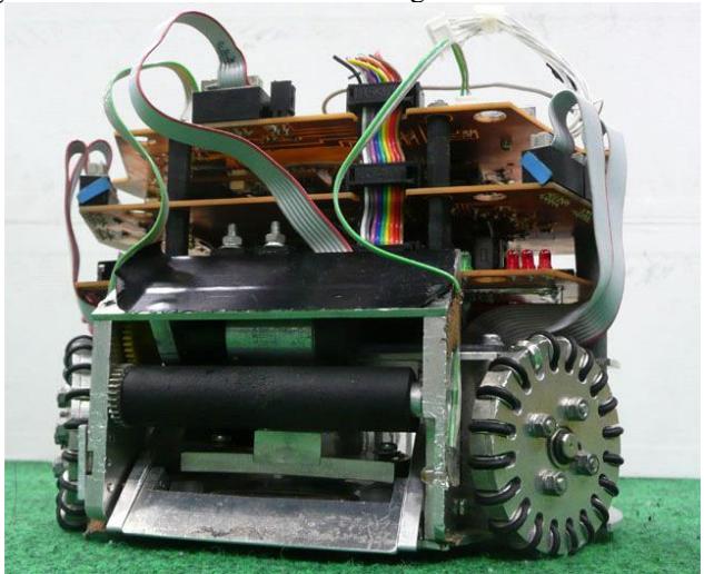
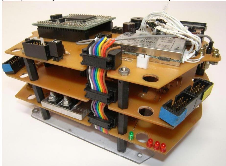
The robot consists of three electronic boards. There are the main board, motor drive board and kicker board. Main board and motor drive board handles most of the robot's task. Kicker board is used to control the kicking action taking account for the competitive situation such as control of the voltage, charging time. They are communicated by UART (Universal Asynchronous Receiver Transmitter). If we would like to partially change the electronic circuit, using of the standard products (UART) will be easy to maintain with no influence on the other parts.
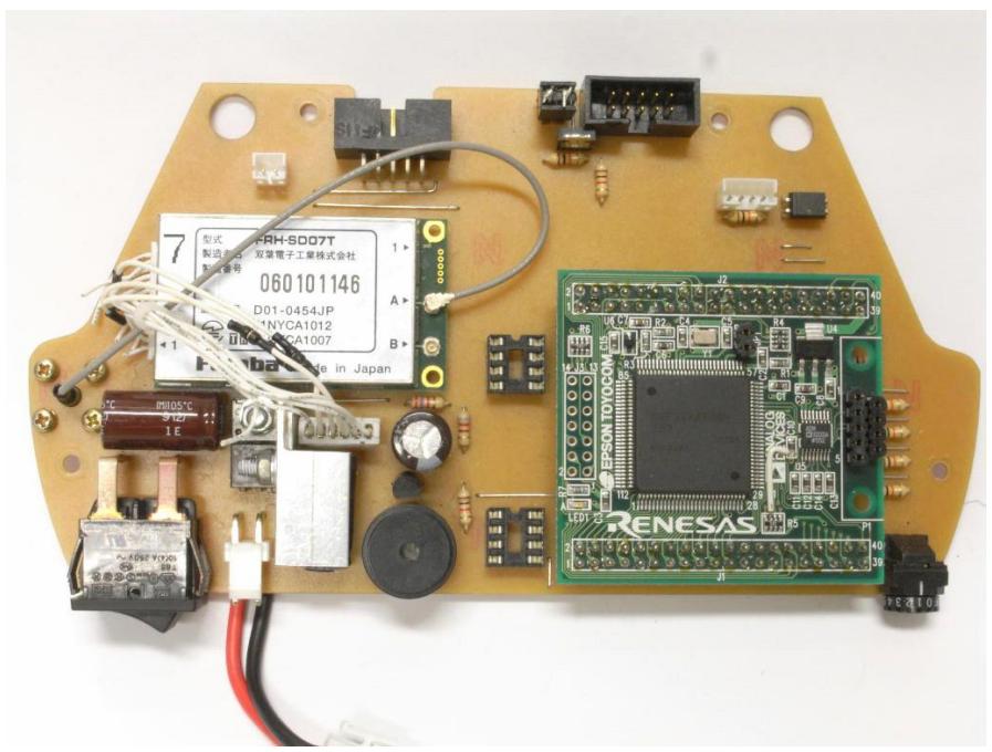
Main electronic board
Main board receives commands and data from AI system, and drives each device. This board communicates motor drive board and kicker board by UART protocol, respectively. Main board has a CPU of SH7144 (SH2) RISC type. The frequency is used by 50MHz. The wireless module is used FRH-SD07 (Futaba). It uses 2.4GHz band. This module is modulated by DS-SS method, and is communicated to main CPU by UART.
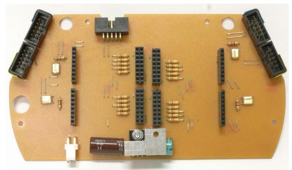
Battery and Power supply
Each robot uses 3-cell lithium polymer battery with capacity of 1500mAh and 11.1V made by Hyperion LITESTORM VX25C as a power source. The robot is able to run for about 15minutes in the case of using these batteries, but its time is not enough. So, we are going to change the battery into more powerful one.
Motor drive board
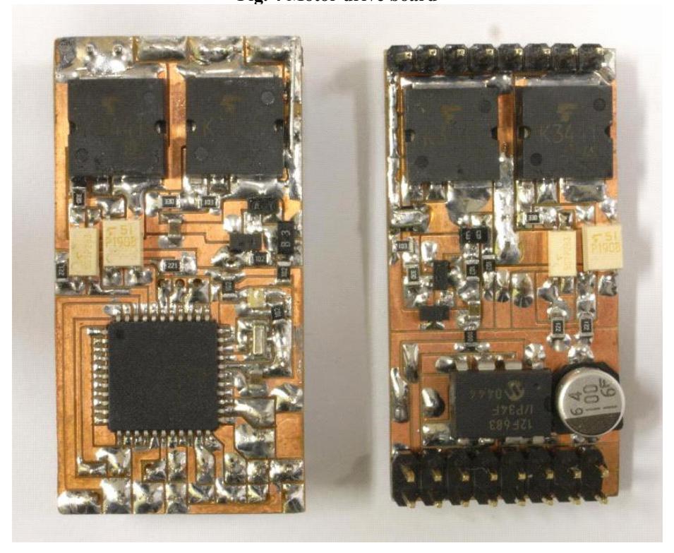
Motor drive board controls the each motors. This board has four drive modules and some connectors. The drive module is in both side of the board. Its height is 40mm, and its width is 20mm. Each motor is controlled by one circuit, respectively. That is, four circuits are included in the board. These drive modulus have two microcomputers called PIC ICs(sub and main). Both PIC ICs control the motor by the signal from the main CPU (SH2). As the results, we could decrease the load of main CPU.
First, sub PIC IC determines how drive the motors, and calculates pulse count of the encoder. Next, main PIC IC received the signal from sub PIC IC calculates the output value compared with the target signal from SH2. After that, main PIC IC converts the output value into PWM signal to drive H-bridge motor circuit. A series of routine process has driven the motors.
Kicker board
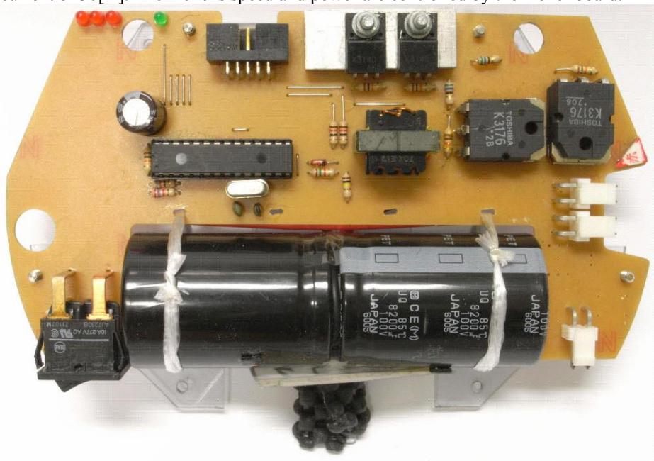
Kick device is energized by solenoid. This board converts the voltage from 11.1V into 200V by transformer to charge kicking energy into the capacitor. The impulse current is created from discharging the high-voltage capacitor. Straight kicker and chip kicker are controlled with the same circuit. Both solenoids are provided with a high current impulse to produce powerful magnetic field within a second. This board consists of power switching devices, such as MOSFETs which is applicable to large current of 30[A]. The kicker's speed and power are controlled by the kicker board.
Software for robot
This program consists of the main program and two interrupt programs. Main program initializes parameters and peripheral devices. After that, it keep waiting for interrupts. When the interrupts occur, the program executes the interrupt processing. One of the interrupt program is receiver program. It has a role to receive the data from wireless module. If the case is happen, it sets receiver flag. Another interrupt program is the timer program. It has a role to check the process time. A timer flag is set every 4 [msec].
Motion Control Program
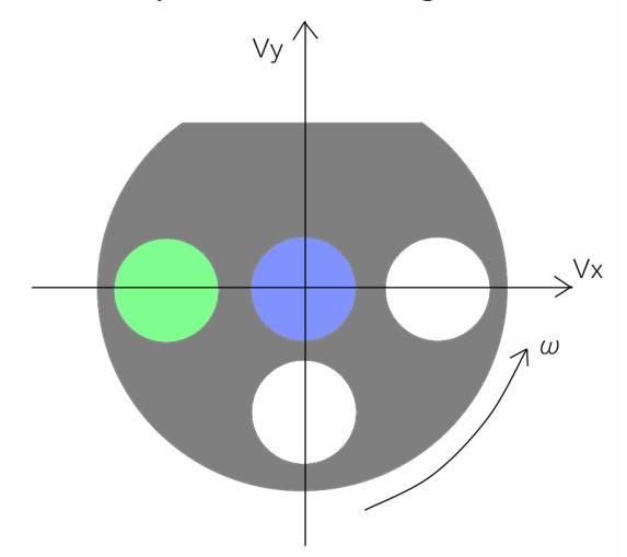
Our robots have used ring-wheels. They can move in all directions to control the reaction force of wheels. Robot receives the data for the velocity, angle and angle velocity. The wheel velocity is obtained from the receive data. The coordinate system of the robot is shown in Fig. 7. Figure 8 displays the detection method of wheels' position. Each wheel's velocity shown as v1~v4 in Fig. 8 are calculated by formula (1).
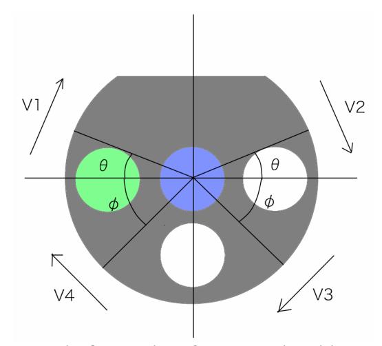
$$\begin{cases} v_1 \ v_2 \ v_3 \ v_4 \end{cases} = \begin{cases} \sin \theta & \cos \theta & -r \ \sin \theta & -\cos \theta & -r \ -\sin \phi & -\cos \phi & -r \ -\sin \phi & \cos \phi & -r \end{cases} \begin{pmatrix} v_x \ v_y \ \omega \end{pmatrix}$$
AI system
Strategy System
Strategy system has a very important role to generate the actions of each robot. Strategy system has been written by C++ language. The system decides the game plan by the information from both of referee signal and vision system. In this section, we describe the modules in strategy system and simulator system.
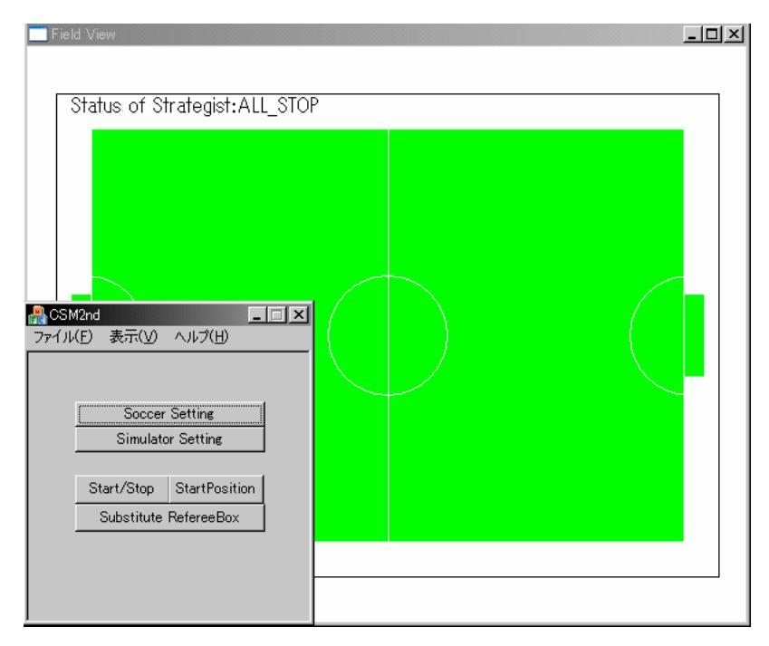
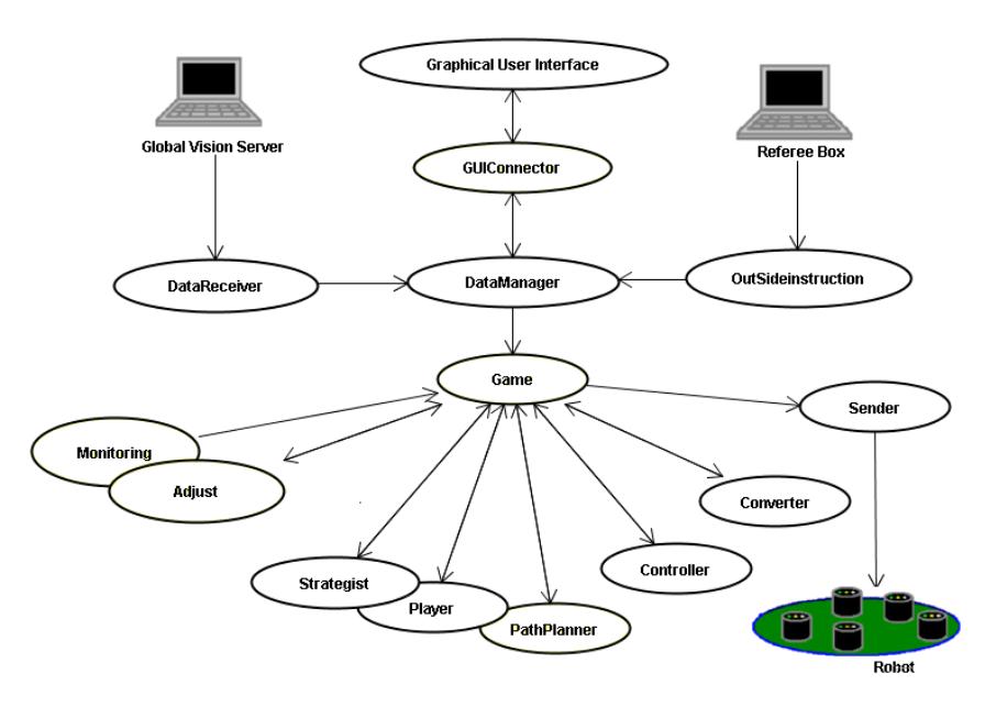
Each module has a role and meaning of followings.
[GUIConnector] This module is used for connection of GUI and Main programs.
[DataReceiver] This module is used for transformation of data for AI sever which received from image recognition sever, and for storing to DataManager Module.
[DataManager] This module is used for analysis to calculate the velocity of robot and ball with the data received from Data Receiver Module through the Kalman-filter. The setting data of GUI are also administered in this module.
[Game] This module is a main system. This module has a role to execute the connection among the other modules. The dependence between DataManager Module and other module is decrease by using of this module.
[Monitoring] This module is used for output the text string which registered in each module to GUI.
[Adjust] This module has a role to adjust and reload by GUI the data which registered in each module.
[Strategist] This module makes the game plan for Player.
[Player] This module has a role to determine each robot's actions and target position according to the strategy instructed in Strategy Module.
[PathPlanner] This module has a role to search the shortest path to move a robot using the present robots' position and target position made by Player Module.
[Controller] This module has a role to make the output information such as speeds, angles and positions for the robots based on the target position and target speed, the present speed.
[Converter] This module has a role to improve the output data according to the transmission protocol.
[Sender] This module sends the data to robot.
[OutsideInstruction] This module has a role to connect other application to DataManager module such as referee box.
Simulator
Recently, a speed of development for strategy is getting fast. Now, we are in the situation to code the strategy program as soon as possible. In the case of the debugging of software, if we use the actual robots, actual robots' life time will be short. So, we developed a simulator to improve the developing efficiency and decrease the operating time of the robots. The simulator is shown in Fig. 11.
The action and strategy for the robots can be checked in this simulator. Especially, it is very effective for development of the strategy in short period of time. As the result, we could make multiple plans for the game.
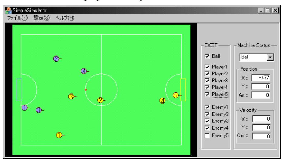
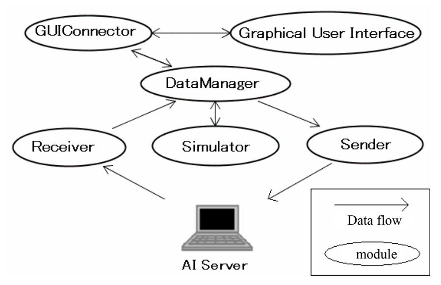
Figure 12 shows the architecture of simulator. It is for increasing maintenance performance. The modules can be change without changing other module. So, we can change easily if we need.
Each module has a role and meaning of followings.
[Graphical User Interface] This module is a main part of controller for simulator. It is used for analysis of the robots' motion through the various configuration of the robots by using the mouse. Fig. 11 shows GUI of simulator. An event process such as click are done.
[GUIConnector] This module is used for creation of structured programs.
[DataManager] This module is used for storing of send data. If use this module , we can get log file easily.
[Receiver] This module is used for translation of data which is sent from AI server to simulator module.
[Simulator] This module is used for calculation of robot's position from storing data in DataManager using physical simulator.
[Sender] This module is used for sending of the data which translated from that of simulator module for image recognition sever.
Development of new robots
The entire structure design
At present time, we have changed three parts.
- Replacement to brushless DC motors (Maxon EC45flat) from brushed one (Maxon REmax24).
- Redesign of chip-kick device.
- Whole mechanical redesign taken into account of maintenance.
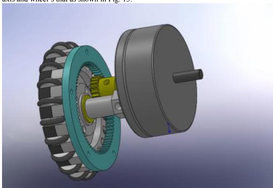
First, the motors which connect four ring-wheels were replaced to brushless motors (Maxon EC45flat). They were used pinion gear with 20 teethes and internal gear with 72 teethes. That is, the reduction ratio is 1:3.6. The robot has not enough space to set the gear box. So, we had to redesign to take account of narrow space between motor's axis and wheel's that as shown in Fig. 13.
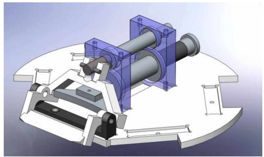
Second, the chip-kick devices were redesigned. The solenoid of chip-kick device was under a normal kick device for previous design. But the solenoid often electrically short out because of rubbing itself against floor. Thus, we replace the solenoid of chip-kick device on that of the normal kick device as shown in Fig. 2. As the results, we solved the problem mentioned above. Furthermore, because of large space between chip-kick device's bar and solenoid, it could get more kick power due to the principle of leverage. In addition, the redesigning brought many advantages for robot performance, e.g., more precise pass by kicking the center of a ball.
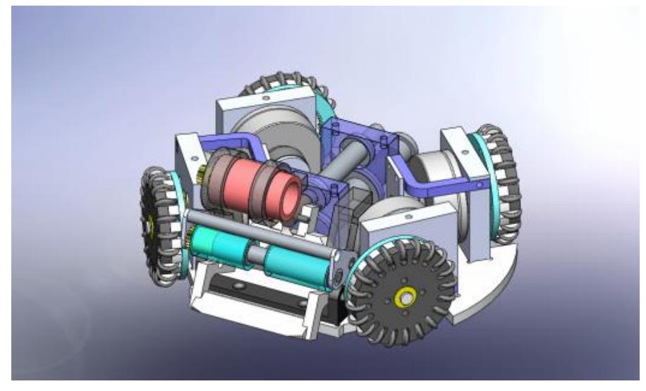
Finally, whole mechanical structures were improved taken into account the maintenance. Our robot had many problems in play because of components from a lot of hand-made parts. At present, we replaced the base-plate to thick one and also made the dents on the plate. The wheel units and kick devises were embedded in the plate as shown in Fig. 3. As the results, the number of screws to fix on the body were able to decrease because of the dents were worked effectively as shock-absorber against the forces from various directions. If the robot is broken, it will be fixed up easier due to the geometric design.
Evaluation of wheel structure
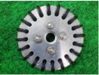
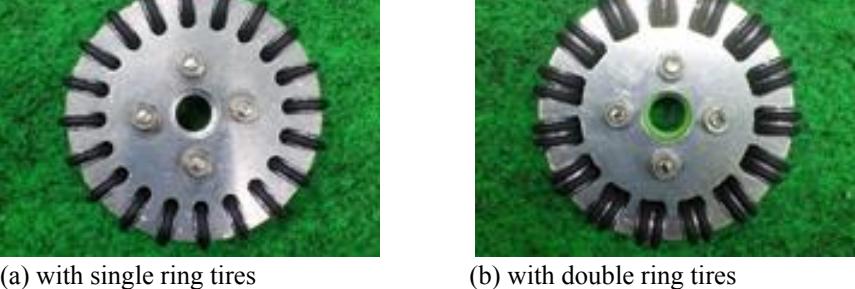
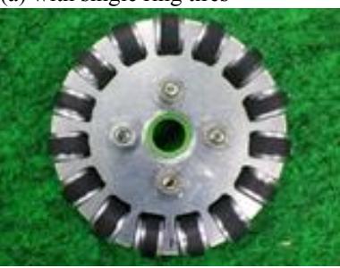
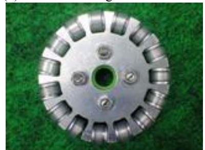
Robots could run faster than last year by replacing the motors. As the results, robots were required high performance for ring-wheels. So, we tried to improve the ring-wheel's structure. We had tested some types of ring-wheels as shown in Fig. 16(a)-(d). The (a) is the present type which has thin single tire with every thin unit house. The (b) type has double small tires with every unit. The (c) and (d) types have thick small tires which made normal rubber and silicone rubber tube, respectively.
![Average time to reach to 1[m/s] from static condition for the robot](/tdps/soccer_smallsize__2010__KIKS/_page_14_Figure_11.jpeg)
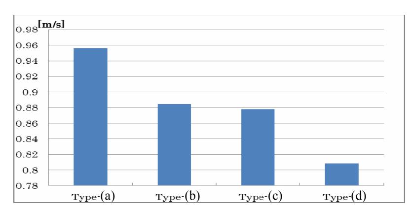
The experimental results of their performance are shown in Fig. 17-Fig. 18. Figure 5 shows the average time to reach to 1[m/s] from static condition. Figure 6 shows the average moving speed on the same condition. Summarizing the results, the (a) type showed the most stable and best performance. Thus, we decided to use (a) type.
Chip-kick device structure
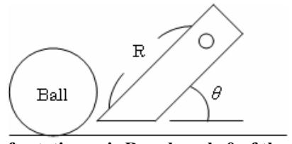
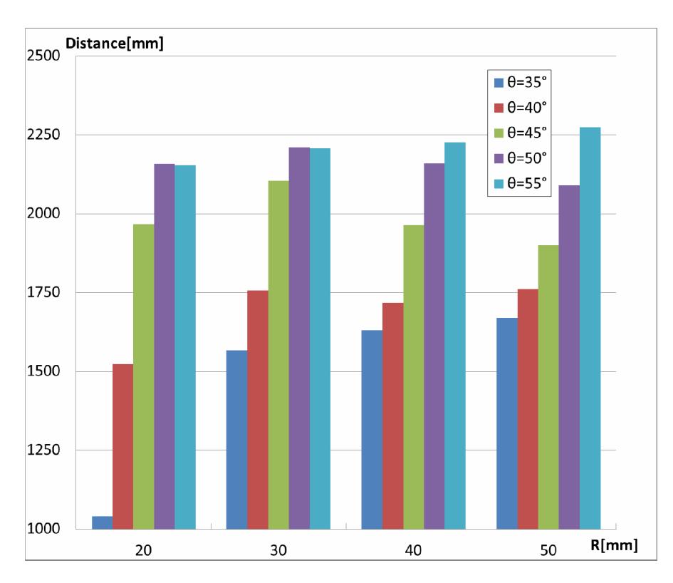
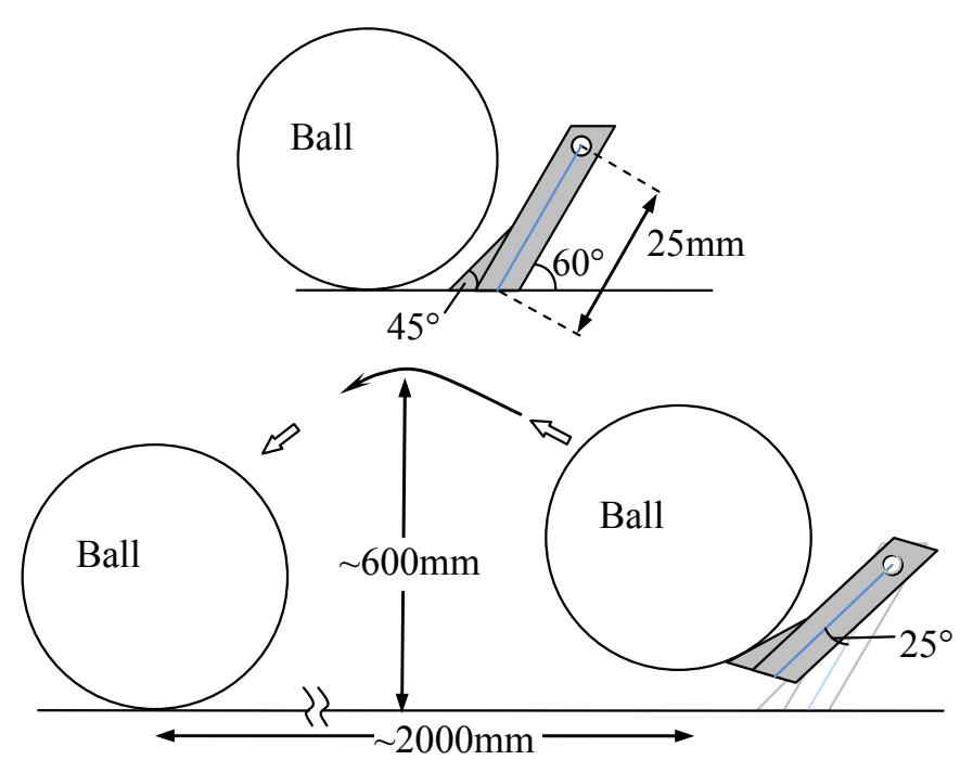
The chip-kick device was also tried to improve. We investigated the relation between the length of rotation axis and angle within the limits of the space. By determining the length R and angle θ, respectively as displayed in Fig. 19, we have measured a range of ball when the R and θ were changed. The result shows that a range of ball is strongly depend on the θ as shown in Fig. 20. On the other hand, the R is shown enough to have only a few cm. Thus, we decided tentatively that the R is 25mm and the θ is 60°. A kicked ball reaches a height of approximately 600mm. Obtained actual performance is shown in Fig. 21.
Dribbling device structure
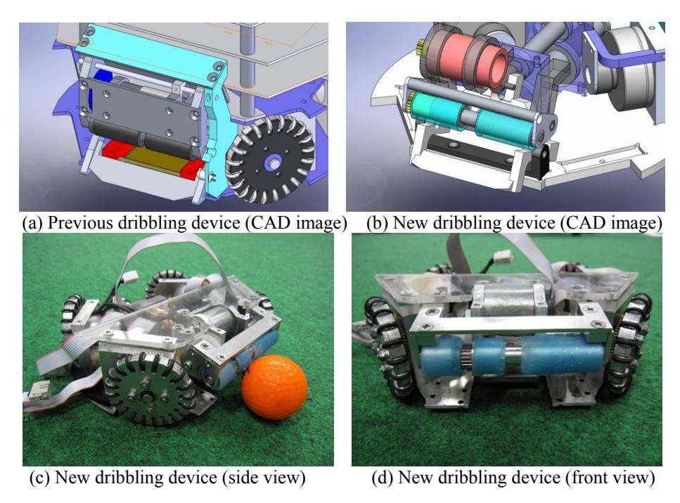
In previous robot, we have used the RE-max17 motor for the dribbling devices. But the motor did not have good enough performance for pass and shoot. So we tried to change that motor into RE-max24. The motor's power has increased from 4W to 10W. In addition, we just changed the dribble devices. Table I shows the performance of new dribbling device. The previous and new dribbling devices are also shown in Fig. 22.
Characterizations of new and previous motor.
| Element\Motor | New(Re-max 24) | Previous(Re-max 17) |
|---|---|---|
| Power | 10 Watt | 4 Watt |
| Diameter of Roller | ~15mm | ~13mm |
| Rotation Frequency(Roller) | 8800rpm | 3900 rpm |
Detecting device for a ball
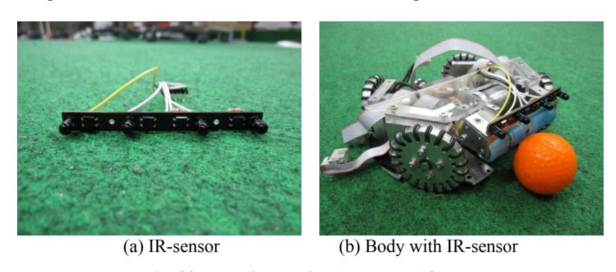
Up to now, the IR-Sensor was only used to find a ball in our robot. So, we attached a new another IR-Sensor to check the position of the ball, and to enhance the performance of catching the ball. As the result, the robot came to check the difference of the position between the ball and robot, and obtained the good performance for catching the ball. Attached new IR-Sensor is shown in Fig. 23.
Electronic circuit for brushless DC motor
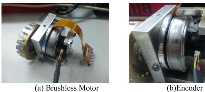
We decided to use brushless DC motor because it is becoming one of the standard equipment of the robots among the best teams in SSL. We replaced the motor to Maxon EC 45 flat from Maxon RE-max 24. The motor is popular in the best team. The motor's power is more than six times compared with conventional RE-max24. Therefore, the gear ratio could change from 8:60 to 20:72. As the result, the machine was able to run more than 1.5 times faster than previous one.
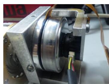
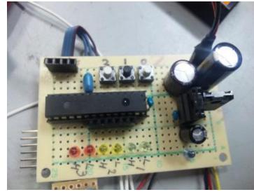
There are two sensors in the motor. That is, the encoder and the hall sensor built in the motor. E4P made by US DIGITAL was chosen as the encoder. Since its resolution is 1440 pulse per revolution, it came to control easier in detail.
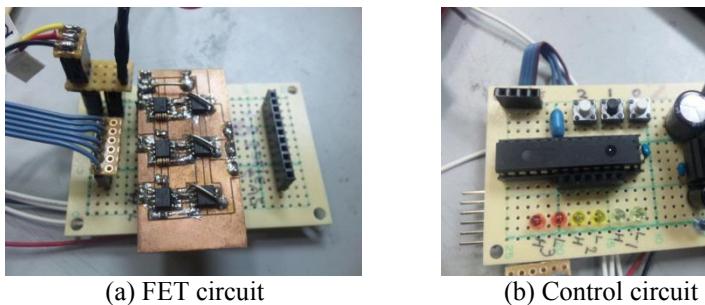
The Microchip dsPIC30F4012 was used for each motor's control. The PICs were connected to the motor through FET drive circuit. Each PIC was commanded by SH2-7144 of Main MPU.

Conclusions
In this paper, we describe mainly the specifications regarding conventional system of mechanical, electronic and AI design. We have a requirement of use of SSL-vision in this year. Thus, it will be very important that the AI design and the robot's kinematic performance is excellent. Our new hardware design have been also introduced.
The performance of our robots is getting high over the year. The cost performance is very high in fact, because of most of devices are hand made by students.
We hope that our robots will perform better in this coming competition than that of last year. We would like to keep joining such competitions continuously in the future.
References
- Touko SUGIURA, Masato WATANABE and Kazuaki ITO: Practice of Creative Education Taken into Account the Continuous Participation to the RoboCup Small Size League and World Competition, Journal of Education in the Colleges of Technology, 32 (2009) 345. [in Japanese]