KN2C Small Size Team Description Paper
Milad AbaeiRad, Majid Ahady, Sayyed Ata-o-llah Khadivi, Salar Moghimi, Faraz Fallahi, Mostafa SaeediMehr, Adel HeydarAbadi
K.N.Toosi University Of Technology
Abstract This is a paper about KN2C Small Size Soccer Team which is divided to four parts. These parts are mechanics, electronics, image processing and other software.
1 Introduction
KN2C team has started its acƟviƟes since November of 2009. But researches about this field returns to the time when most of team members were in Allame Helli high school and some of them were working on small size soccer and junior soccer leagues in 2007. Back then team members had some achievements which I can mention to compeƟng in SSL of Iran Open 2008 ( I consider this as an achievement because we were high school students ), second and third places of junior soccer in Iran Open compeƟƟons of 2007 and 2008, and second place of junior soccer in Kharazmi naƟonal compeƟƟons in 2008.
After team members became to K.N.Toosi University, they arranged their new team under supervision of Dr. Mehdi Aliyari – a member of mechatronic group – and they are looking for a very glorious future.
2 Mechanics
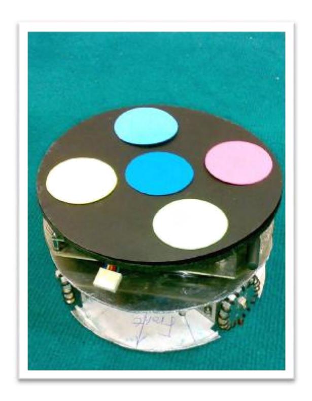
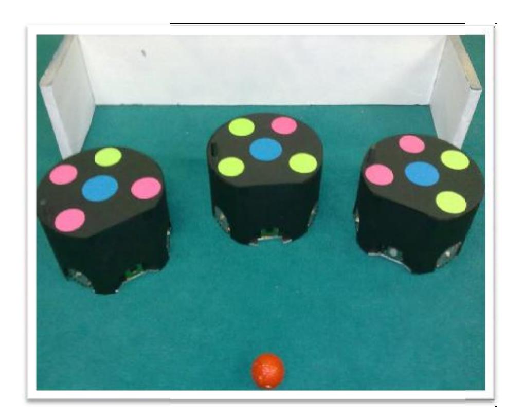
Robots are made of three surfaces. First one consists of motor solenoid, capacitors of kick locate different parts of this surface in the right wanted to set center of mass in order to be in the center of the surface. It makes torque equal to zero. kicking board and batteries. It is considered to place. Because we made of motors, in the
2.1 Dynamic System
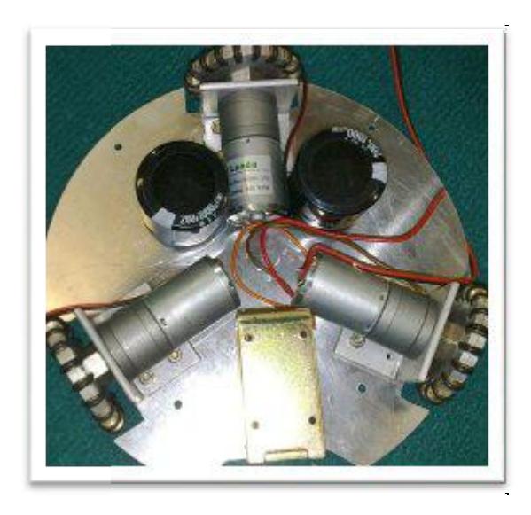
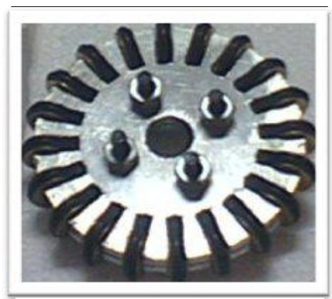
Speed of motors with gear boxes is 600 RPM. Power supply of motors is 12 V and gear boxes are 13.6/1. Angle between each pair of motors is 120° because this type of placing motors allows robots to move in all directions of X-Y surface and turn in direction of Z Axis. Because of this wheels are omni directional.
3 Electronics
3.1 Microcontroller
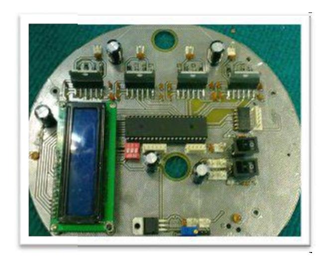
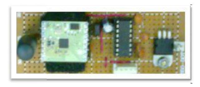
Microcontroller, which is used to process data in robots, is ATmega-16 (belonged to AVR family). Procedure is this, data arrives from wireless module. Then microcontroller get's this data with USART protocol. Finally microcontroller send's orders to mechanical parts. Some other duties like reading voltage of batteries and operating kicking board is devolved to microcontroller.
3.2 Wireless communication
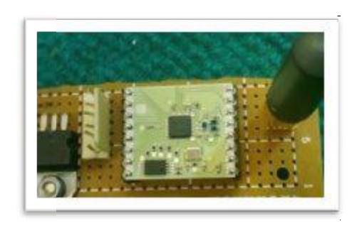
MULTICHANNEL RADIO TRANSCEIVER RXQ2-XXX GFSK modules are used to connect computer to robots via radio waves. These modules are available in frequencies of 433Hz and 868Hz. So competitions which our opponent has same frequency. it can be changed in
3.3 Motor's deriver
Each motor is operated with a full H-bridge driver named L6203. And speed of motors can be controlled with PWM pulse of microcontroller. (Due to connec ng enable pin of L6203 to microcontroller)
3.4 Kicking
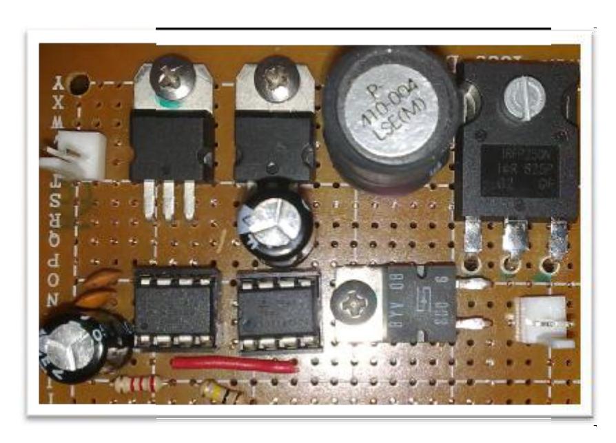
Each robot has a direct kicking system and a boost convertor circuit is used for kicking. With connecting and disconnecting voltage across the inductor, voltage increases. (It's possible because of electrical property of inductors). In this case 12V is converted to 150V. And it is stored in capacitors. Two $1100\mu F$ capacitors are used in each robot. In time of kicking energy of capacitors will be vacated in solenoid and it will kick ball directly.
4 Image processing
4.1 Hardware
4.1.1 Cameras
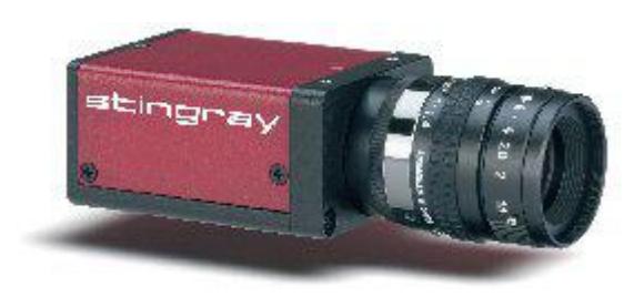
Hardware which is needed to run the process is 1394 cameras. In this case we use two sƟngray_046Ccameras. The most important property of this camera is its high speed (61fps). This property makes it efficient for image processing. Technical features of camera are written in this table:
Table 1: Technical features of Stingray_046C
| Stingray F-046 B/C | |
|---|---|
| Image device | Type 1/2 (diag. 8 mm), progressive scan CCD, SONY ICX 415 |
| Picture size | 780 (H) x 580 (V) |
| Cell size | 8.3 μm x 8.3 μm |
| Resolution depth | 8 bit / 14 bit (16 bit in High SNR mode) |
| Lens mount | C-Mount / CS-Mount |
| Digital interface | IEEE1394b, (IIDC V1.31) S 800 daisy chain |
| Transfer rate | 100 Mbit/s, 200 Mbit/s, 400 Mbit/s, 800 Mbit/s |
| Frame rates | Up to 61 fps (full resolution) |
| Gain control | Manual: 024 dB, auto gain |
| Shutter speed | 30 μs … ~ 67 s, auto shutter |
| Image pre-processing | LUT; shading correction; High SNR mode; white balance; color interpolation (debayering); local color anti aliasing; hue; saturation; sub-sampling; 2x - 8x binning (only b/w) or sub sampling; separate reference AOI for auto features |
| Grabber features | 32 MB on-board memory; deferred image transport; trigger delay; multi-shot; mirror image; several trigger modes; SIS (secure image signature); sequence mode; storable user sets |
| Power requirements | DC 8 V - 36 V; < 3.5 W @ 12 V |
| Dimensions | 72.8 mm x 44 mm x 29 mm (L x W x H) |
| Mass | 92 g (without lens) |
| Operating temperature | + 5 … + 45° Celsius |
| Regulations | CE, FCC Class B, RoHS (2002/95/EC) |
4.1.2 Lens
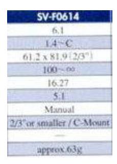
Model of lenses is SV-F614. Focal length of this model is 6.1 mm. Efficient focal length ,which is calculated for SSL field, is 4.8mm. But a lens with this focal length wasn't available and we used an Upper one. Technical features of this lens are written in this table:
4.2 Software
Software is divided to three parts. These parts are SSL-vision, planning and microcontroller's program.
4.2.1 SSL-Vision
SSL-Vision is an open source program which is written for image processing. Due to rules declared by SSL organizing committee, using this program is mandatory for all of teams since 2010. So we decided to use this program for parƟcipaƟng in robocup 2010.
This program run's in Ubuntu 8.4 and aŌer receiving video from cameras and processing it; SSL-Vision determines angles and coordinates of robots and coordinates of ball. Then this data is sent to another computer.
4.2.2 Planning
After receiving data from SSL-Vision and processing them in second computer, tactics of game will be planed. Then orders will be sent to robots via wireless module. From abilities of this part I can mention to finding efficient robot for offense, finding direction of robot's movement, kicking and locating robots. Programs of this part are written by QT4.
4.2.3 Microcontroller's program
Program's for robots which are programmed in microcontroller are written by Code Vision AVR. This program is concordant with C language.