Khainui Team Description for Robocup 2010
Srikluan M., Srithong A., Prisuwun S., Paocharoen J., Chaiburee W., Karnjanadecha M.
Department of Computer Engineering, Faculty of Engineering Prince of Songkla University, Songkhla, Thailand
Abstract This paper describes the current state of development and future plans for Robocup 2010 of the Khainui team. We redesigned new robots for this year's competition. Each of our robots can perform chip kick and flat kick. Last year, we used the back-EMF technique for motor speed control. This year, we employ optical encoders in order to achieve precise speed control. Our AI system has been modified to run at 60 fps and to make use of dual kicking mechanism.
1. Introduction
The first appearance of team Khainui in World Robocup event was in Suzhou 2008. Our best result was passing into the last 12 teams. It was a great experience to be part of such a wonderful and exciting event, where hundreds of people are working tirelessly on their robots.
The robots used in Suzhou 2008 were our 2007 design, and simplicity was our philosophy [1]. Our old robots were mechanically simple and low cost. However, they lack some features that are very important for very high standard of today's game. Our old robots did not have a dual kicking system. Each robot equipped with a flat kicker or a chip kicker. This is difficult for the AI software to switch players because all robots are not the same. In addition, the robots did not have a dribbler or any other mechanism to hold the ball, which is very important feature for accurate shooting and ball passing.
The mechanical weakness of our previous year's robots was in their wheel shafts which can be bent easily when colliding with other robots. The wheel shaft was 4 mm in diameter and was part of the gear box which was too difficult to make it stronger.
We redesign new robots to overcome the problems. Our new robots employ dual kicking system, have a dribbler, and use rotary encoders as speed sensor. More parts are crafted with CNC machines. The new robots are stronger but heavier than old robots.
The remaining portion of this paper explains every part of our Robocup system in detail.
2. Mechanical design
The robots have more parts than our previous design. This is due to the introduction of the dual kicking system and the dribbler. Many parts, such as the gear, the motor fixer and all parts of the dribbler, need to be high precision, so we paid a machine shop to CNC these parts for us.
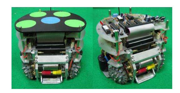
Our robots are built to comply with the Robocup SSL rules, where the diameter is 178mm, the height is 145 mm and the ball coverage is less than 20%. Figure 1 shows a photo of our 2010 robot.
2.1 Motor and gear
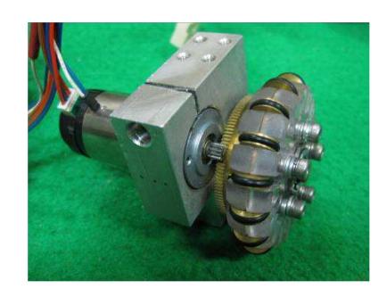
We still use the same DC motors as we used for last year. They are surplus Namiki 22CL-3501PG80:1's, which come with a 80:1 gearbox, The gearbox is too slow for our application, so we remove the gearbox and use only the motor. The motor has a 12 teeth spur gear permanently attached to its shaft. We couple the motor with a 120-teeth external spur gear which yields a 10:1 gear ratio. The wheel is directly connected to the 120-teeth gear. Figure 2 shows the motor, gear, wheel and the motor fixer assembly.
2.2 Omni-directional wheels
The wheel hub is milled from a clear 6 mm polycarbonate sheet. The rollers around the hub are machined from brass. Both parts are manufactured in-house using a small-sized CNC machine and a lathe.
2.3 Kickers
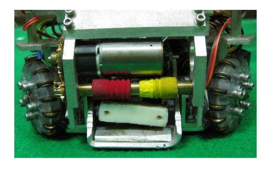
Like other teams, this year we put 2 kickers in each robot, one is a flat kicker and the other is the chip kicker. The flat kicker is energized by a push-type solenoid. It stays on the base of the robot. The chip kicker employs a pull-type solenoid and it is located above the flat kicker's solenoid. We made our own solenoids. The solenoid's bobbin is machined from a piece of cast nylon. Each solenoid is wound by a #23 AWG copper wire for 300 turns. Figure 3 shows a close look at the kickers.
2.4 Dribbler
It is the first time that we attach a dribbler to our robots. We think that the dribbler is the most important device for accurate shooting and passing. However it is also the most difficult device to design and make good use of it. To our experience, the only team that can make excellent use of the dribbler is CMDragon.
Although, the dribbler adds more weight to our robot and our team does not have much experience on it, but we still hope it will work fine and will be beneficial for our game play.
3. Electrical design
Compare to our last year's robots, the electrical design is significantly more complicated. Our previous robot used one ARM7 processor to do all the tasks but this year, each robot has five dsPIC and two AT89LP4052 microcontrollers.
3.1 Microprocessors
As mentioned earlier, this year we use an optical encoder as a speed sensor for motor speed control. Only a few microcontrollers in the market, have encoder interfacing circuitry. Microchip's dsPIC 30F2010 is one of such microcontrollers. We choose dsPIC for our application because of its local availability. Since one dsPIC processor can handle only one encoder, then we four dsPIC's for four wheels and the 5 th dsPIC for some other functions, such as kicking and dribbling.
Our motor speed control algorithm utilizes the standard PI (proportional and integral) control. The close-loop rate is 1,000 Hz. The dsPIC processor that control the wheel receives speed command from the wireless receiver processor (89LP4052).
3.2 Speed sensor
Rotary encoders are used in our robots for the first time. Last year, we used back-EMF method for motor speed control by measuring the voltage across the motor terminals to estimate its speed using the ARM7's built-in analog-to-digital converter. This year we acquire low-cost, 100 ppr, depressive-type, rotary encoders from US Digital [2]. Our motor has a long enough shaft at the end to attach the encoder.
3.3 Battery
Each robot is powered by 2 packs of 11.4V 2200 mAh Li-Po. Fully-charged batteries can run the robot for about 30 minutes.
3.4 Wireless communication
To receive commands from the AI system, the TRF2.4G wireless module was used. This module is controlled by a 89LP4052 microcontroller. Our wireless receiver can receive command packets from the AI system at a rate of 60 Hz without any problem.
The data transmitted from the PC to the robots are formatted into a 25-byte packet. The first byte in the packet represents the packet start byte (the value was 0x6A). The next 5 bytes are commands for Robot 0, the next 5 bytes are for Robot 1, and so on.
The 5-byte commands can be interpreted as follows:
Byte 1: speed of wheel 1 Byte 2: speed of wheel 2 Byte 3: speed of wheel 3
Byte 4: speed of wheel 4
Byte 5: kick and dribble command
After receiving the wireless command the microcontroller will send wheel speeds and other commands to 5 dsPIC processors using a highspeed serial communication.
Each robot also has a wireless transmitter on board. It has similar circuitry as the receiver. We intend to use it to communicate back to the AI system to notify the ball possession status.
4. The Vision System
We use a pair of AVT Guppy IEEE1394 cameras for practicing in our lab. This camera can capture 640x480 pixels video image at 60 fps. We are currently switching to ssl-vision which is compulsory in Robocup 2010.
5. The AI Module
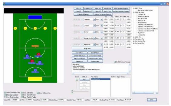
The core of the AI module is very similar to last year's system. Figure 4 shows a screen shot of our current AI system. We are working on improving move-to-ball skill to make use of the dribbler that we have on our new robots. Also kick speed can now be controlled. The AI must be able to choose appropriate kick speed, especially when executing a ball passing skill.
Passing function is one thing that our team is not yet mastered. We are improving our passing skill by making use of our new dribbler and kickers.
6. Future plan for Robocup 2010
We have much work to do on improve our AI system. We have to refine our AI system to work with ssl-vision. We have to test our 2010 robots for their robustness and make minor adjustments if necessary.
7. Conclusions
A brief introduction of Khainui 2010 Robocup team has been described. We are improving our team in many aspects. We hope to do better this year.
8. References
References
- Ruengnium W., Srithong A., Chiangtawan S., Saelee K., Anongthong N., Boonprakob W., Surakamhang T., and Karnjanadecha M., "Khainui Team Description for Robocup 2008".
- http://www.usdigital.com