MRL Team Description 2010
Maziar Ahmad Sharbafi, Mohammad Hoshyari, Saeed Esmaeelpourfard, Omid Bakhshande Babersad, Mohammad Haajseyedjavadi, Danial Esmaeeli
Islamic Azad University of Qazvin, Electrical Engineering and Computer Science Department, Mechatronics Research Lab, Qazvin, Iran
Abstract MRL Small Size Soccer Team is planning to participate in 2010 world games. The team has attended two previous years' wolrdCup and Iran Open competitions and several modifications are made to improve its efficiency in the competitive environment. Our team's activities including mechanics, electronics, software, artificial intelligence and control are described in this paper. Some innovations besides the lessons learned from powerful teams like Skuba, CMDragon and PlasmaZ made the basis of our improvements in mechanical design. Generating new debugging tools like 3D simulator and comprehensive user interface had key role in our robot intelligence progress. Finally, reconfiguring the electrical design, beside addition of Arm to FPGA and new wireless system empowered the robot low level hardware architecture.
1 Introduction
MRL small size team successfully attended 2008 and 2009 Robocup competitions with notable progress, and is planning to participate in 2010 world cup with major changes. From 2008, every year, we produced new robots from scratch and only with the previous experiences. Our three-year program should results in significant growth to be one of the four teams in semi final stage. Considering the capabilities of our robots in the two first years of participation and qualifying to go to the second stage of the competitions, the first steps of our three-year program were passed admissibly. Qualification from Group level in 2008 and 2009 and playing promising games show our progress in these years. MRL ranked 1st in Khwarizmi national robotic competitions in Iran for two sequential years. 3rd and 1st places in Iran open 2008 and 2009 are other honors of our team.
In addition to have experience in other robotic leagues, most of our team members, have a progressive cooperation in these three years. Redesigning the robot structure, from the mechanical scheme to electrical boards prepared a suitable hardware platform. For the first time, producing the robots some months before competitions, using shared vision and generating some basic debugging tools by our software group raised our expectations for a hopeful future.
This paper is organized as follows: Firstly, software architecture including our new approaches and tools are described in section 2. A new electrical design based on Arm micro controller beside FPGA, and other accessories of robots' onboard brain, is explained in section 3. Description of mechanical configuration modification for the newly designed robot which elevates the capabilities of the robots' smooth and reliable motion is the subject of section 4. A brief overview of the motion control approach is presented in section 5. This section is under investigation and the results will be accessible in our further publications.
2 Software
MRL team attempts to elate the team performance by developing required improvements in robots' intelligence, control, game strategy and coordination. To achieve these targets the preliminary step was debugging the previous algorithms which needed some tools to evaluate codes and algorithms. For this reason we tried to produce some tools to visualize and simulate a game with its problems as much as possible. With reliable shared vision system one of our most important problems which was designing image processing program was solved.
In summary, our software program contains 4 mainly part:
a) AI console b) UI
c) Simulator d) Prediction and Tracking
2.1. AI Console
Our AI application had some problems because of lack of time in 2009. In this year, we are trying to solve the problems like instability in role assigning and motion control for our new robots and AI application. In [2] we described our roles and skills details and relations between them which are inspired from CMU game structure [3], [4]. Also we added a new layer in our hierarchical playing architecture which is inserted between role and skill, called technique. A technique is not a role (the "play" is constructed based on roles and each strategy utilizes some specified roles with unique arrangement) but it can apply skills to generate new behavior. For example chip dribble is a technique that uses "go to point" and "aim and kick" skills. There is a technique matcher to match the feasible technique in all conditions too.
Last year a flexible comprehensive software structure was designed but the time was not sufficient for debugging the code especially in practice. Working on robot which never was manufactured so long time before competitions in previous years, aided us to increase their abilities in this year competitions. We hope that more reliability in our software and hardware can improve our performance more than ever.
2.2. User Interface
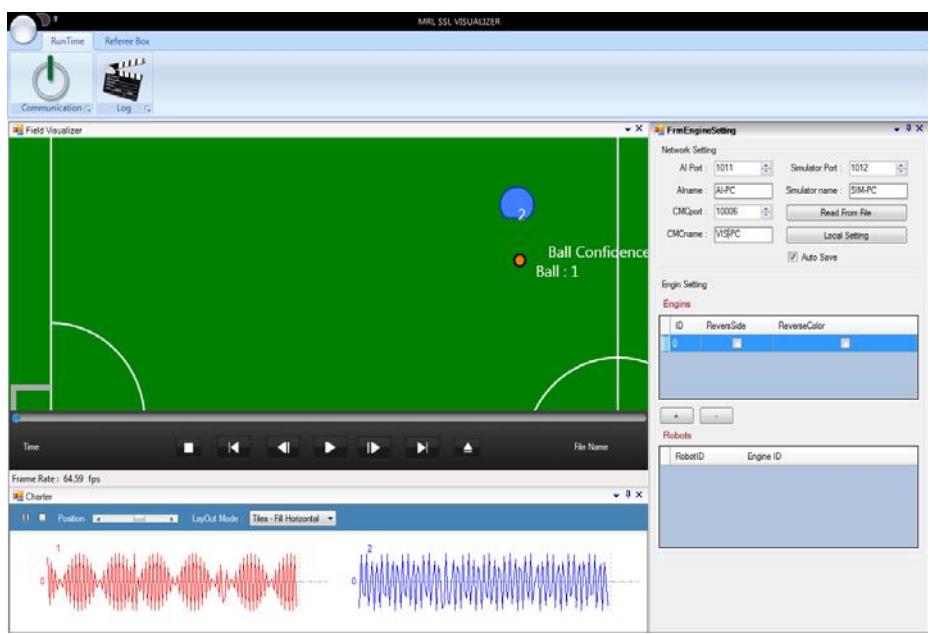
Previously our AI software was run in the console application to make it independent from graphical usage. We found that for online and visually debugging, more complete user interface is needed. Our user interface is independent software for visualizing everything, like real time diagram plotting, logging and sending commands to AI center. Therefore, we can generate every situation, save and play game log, evaluate different game strategies and etc easily. In figure 1 a view of the user interface is displayed.
2.3. Simulator
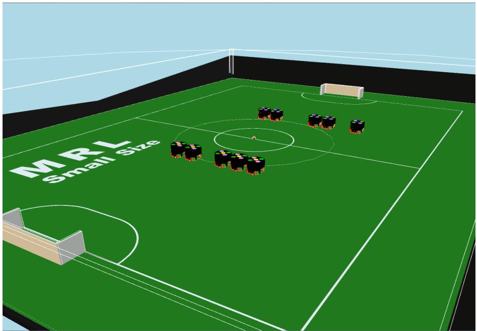
Developing a simulation environment for high level debugging in 5 vs. 5 robot match is an important way to speed up the team parallel working. Thus, it seems that a new 3D simulator considering physical constraints will be so helpful. Instead of enforcing robots to move directly in X and Y axis with their desired velocities, our robots are simulated including theirs wheels and sending torque commands to them. Therefore, the ability of testing robots in slipping conditions was added and the simulator became a perfect lab for motion planning's tests too.
For physics calculation the simulator uses NVIDIA PhysX engine. It is a gpu based engine with a lot of abilities for use. For simulating real condition a wheel shape object had been used and its Omni directional motion is simulated via tuning the physical parameters like frictions and slip in different (lateral and longitudinal) directions. Figure 2 shows a screenshot of our simulator containing whole of its schematic and physics details.
2.4. Prediction and Tracking
Uncertainties, noisy data, delay and interference are some problems of small size environment. Some of such exogenous or internal factors are Image buffering delay in cameras, Image digitalization in computer, decision making's process time, delay of sending packets by wireless and mechanical uncertainties of robots.
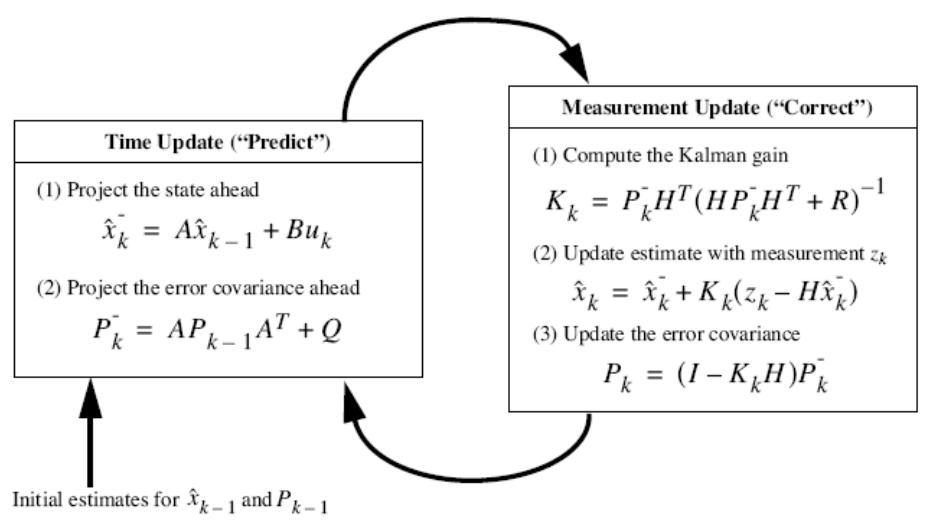
The most common method of prediction and noise reduction is Kalman filter [5], which is utilized in mobile robot navigation frequently [6]. From mathematical viewpoint, Kalman filter estimates the states of the linear system using a predefined model, previous data, output measurement and a white noise model. Kalman filter, as an optimal observer, is an effective method in practice, using minimization of estimation error variance.
In our approach Kalman filter is utilized in two stages: First to compensate the vision noise and process delay and second to predict the ball position in future for catching or cutting. The total delay is calculated and an application is devised to evaluate the estimator. Kalman filter equations and relations between different modules is illustrated in figure 3.
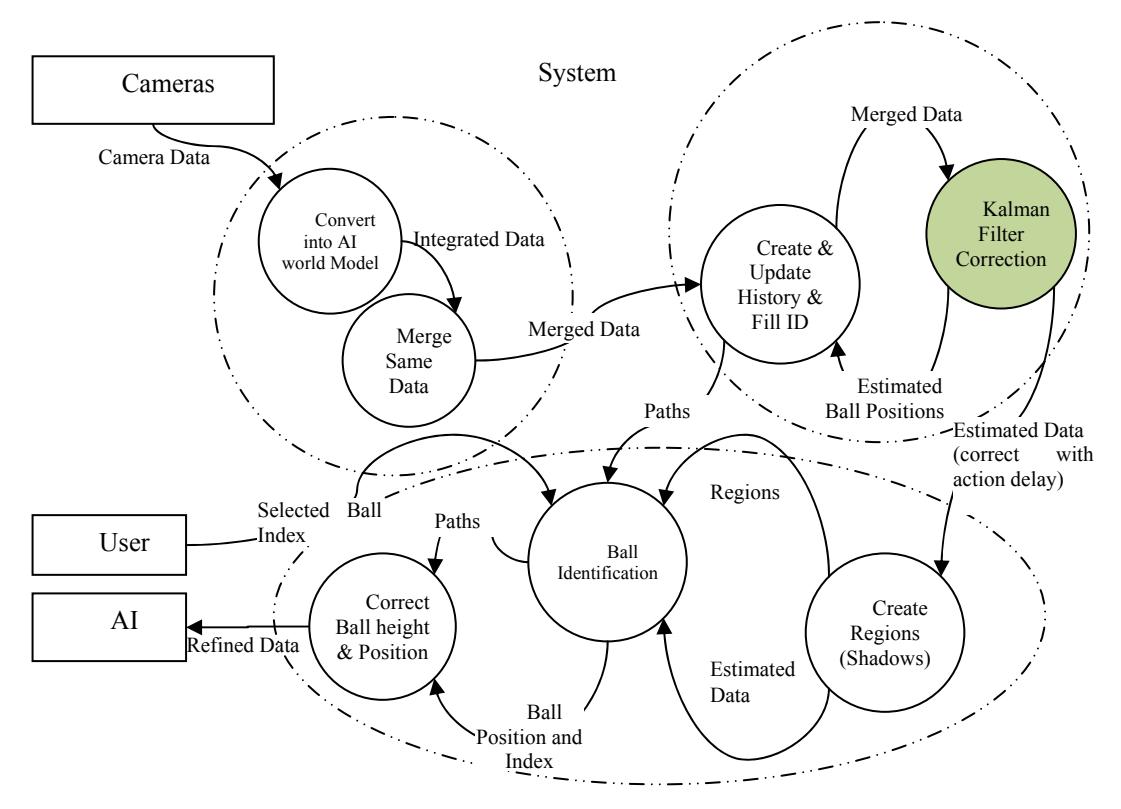
The general software architecture including merger, tracker, prediction, AI and their connections are depicted in figure 4.
3 Electrical Design
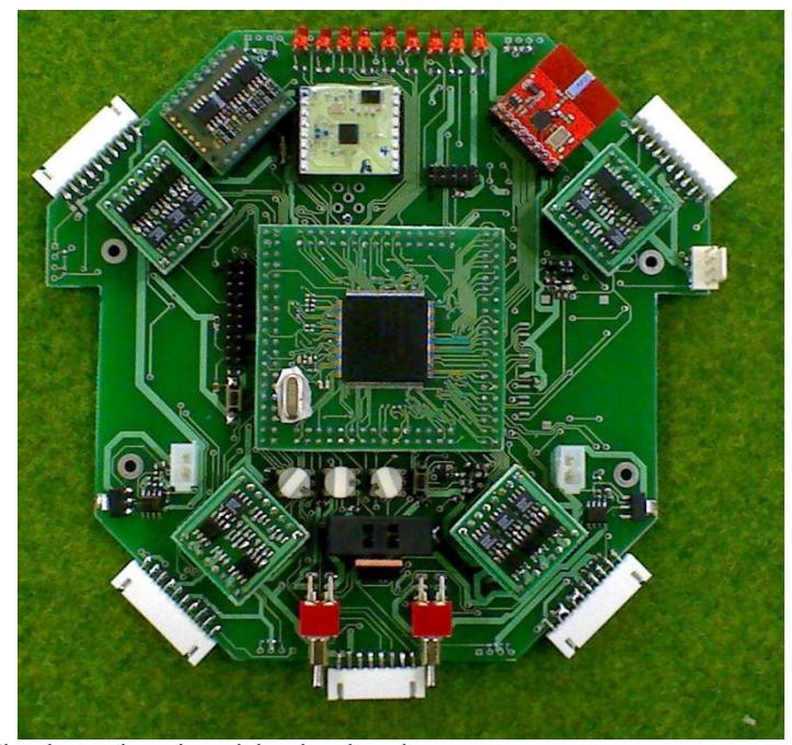
Debugging the hardware was one of our most significant problems in our previous electrical design. To raise the performance of robot low level layer, some modules are replaced by new designed objects which are described in this section. This year, our system consists of a main board and some daughter boards (DB). This approach simplifies the repairing process especially during the matches. Figure 5 shows the main board and its connections. The DBs and other accessories are described in the following.
3.1. Processors Daughter Board (PDB)
In previous year, we utilized Altera FPGA for our all electronics purposes such as control, driving and so on. Although real-time advantages of FPGA are so useful, we suffered from some limitations. The first one was debugging since there was not any reliable and user friendly method for detecting system errors. Due to the soft core emulation implemented in FPGA, the interrupts did not have enough speed which was the second problem. Moreover we used an external memory for storing data. From this point of view that the external memory is considered as an I/O device, data transmission does not have appropriate speed.
Because of the drawbacks mentioned above, we decided to utilize ARM7 microcontroller beside FPGA. It was selected for several reasons such as its powerful debugging capabilities and low-power design of ARM architecture. In addition, the ARM7 with TDMI-S core is one of the best choices for system control. Hence, only real-time tasks such as motor driving are executed in FPGA and all remained parts are implemented in ARM7 microcontroller. Figure 6 represents the relation between ARM and FPGA. According to this figure, the FPGA sends the encoder data and in other side, the ARM microcontroller prepares PWM data for FPGA to drive the motors.
The PDB consists of one FPGA and one ARM processor connected to each other. FPGA duty is to control the motors and ARM processor is used to control the FPGA, communicate to wireless, compute control algorithms, debug the entire system and log the data. We used ARM7-TDMI core and developed the project in KEIL software.
3.2. Accessories:
In this section other accessories are described in categorized manner.
- 1- Wireless Module: The main board receives commands from the AI computer by wireless module. Our communication system is based on the nRF2401 wireless module which is a programmable radio transceiver with a working frequency between 2.4 and 2.52 GHz and a baud rate of 2 Mbit/s. So it decreases the delay of communication to around a few milliseconds.
- 2- Battery: Each robot uses 4-cells of lithium polymer (LiPo) battery, with capacity of 2200 mAH as a power supply. Robots can run for one game with these batteries. When voltage of batteries reduces, the robot switches to sleep mode and stops working. Of course it was monitored by one LED before reaching to low battery state and by a buzzer to show the critical state.
- 3- Kicker Board: The kicker board is designed to control the high voltage. It has one MOSFET for charging and two for kicking. An Atmega8 micro controller is used as controller. It creates pulse, limits the charger and communicates with the processor. The board also contains mosfet driver to turn on and turn off the mosfet in nanoseconds which prevents damaging them.
- 4- Motor & Driver: There are four BLDC (Brushless DC) motors for each robot which is 50 watt Maxon EC45 flat motor and one BLDC motor for the dribbler. Also we use US digital hollow shaft encoder with 360 pulse/cycle resolution to detect the motor speed. All motors except dribbler one are controlled by FPGA and custom designed driver. For dribbler motor we used MAXON amplifier which is reliable and compact.
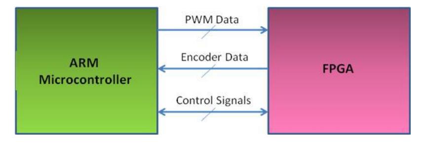
Fig. 6. Communication between Arm and FPGA
4 Mechanical Design and construction
The mechanical system of small size robot consists of wheels, kicker, dribbler and motion system. Some problems in the previous design encouraged us to improve the mechanisms to optimize the mechanical specifications such as weight, reliability, ability to generate complex maneuvers with and without ball, power of direct kick, flexibility of chip kick and etc. To explain these parameters this section is divided to two parts as follows.
4.1. Motion System
The first small size robot which has been made in this center, had three wheels without side gear in 2008 competitions that changed into four wheels in 2009. The current four wheeled robot has been designed with internal gear and more rings in each wheel.
The advantages of the wheels compared with previous ones are smooth motion with lower slippage and vibration, protection against entering pile into the gears, weight reduction and higher precision in manufacturing. The wheels are made from aluminum and o-rings are made from Neopran. The design of the wheels that is onepiece with internal gear results in more accurate assembling process.
Also in order to create smooth motion, two ball bearings are fetched into each wheel. The diameter of the wheel is 54 millimeters, which is 10 mms smaller than previous ones. Table 1 presents a comprehensive comparison between our robots during these three years, (from 2008 till now).
As mentioned before, four brushless DC motors with gearbox ratio of 1:4 are utilized for robot motion. The design is inspired from CMU model [4] with 90 degrees angle between rear wheels and 114 degrees between front wheels. The chassis is a 3mm titanium alloy plate produced by wire-cut manufacturing method and provides a reliable base to install motor stands and driving system, kicking and spin back mechanisms, battery packs, and other mechanical and electrical hardware components.
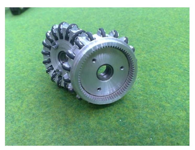
Table 1. Wheel structure characteristics.
| Model | 2008 | 2009 | 2010 |
|---|---|---|---|
| Number of wheels | 3 | 4 | 4 |
| Wheels diameter | 64 | 60 | 54 |
| Wheels thickness | 8 | 9 | 16 |
| Number of rings | 20 | 15 | 18 |
| Gearbox ration | 1:5 | 1:4.4 | 1:4 |
| Material | Aluminum | Aluminum | Aluminum |
| O-rings material | Viton | Viton | Neopren |
4.2 Spin back and kickers
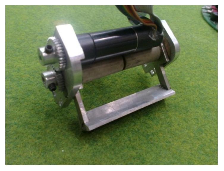
Spin back is made of a motor, steel shaft with 6mm diameter and silicon cylinder connected to the motor shaft with 1 to 1 gear ratio (see Fig. 8). Substitution of 30w FAULHABER motor with MAXON EC 16 motor, in spin back structure, has considerable preference like less vibration. Such effects prevented robot from catching the ball completely especially in curvature like paths and interfered in robot passing with altering the pass direction.
A kicker is formed of solenoid, core and spring. Some modifications are considered to decrease energy consumption in kick process. The core of the kicker is formed of magnetic and non-magnetic parts. That magnetic part is made of ck45 iron and non-magnetic is made of aluminum. Also in previous chip kick system, we had undesired power consumption at hinged base with 140 degrees which has been improved by converting to 90 degrees (See Fig. 8).
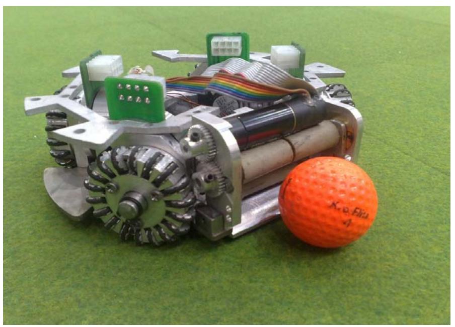
The mechanical structure of our new robots is displayed in figure 9. Reducing the weight and height of the robot from 3.8kg and 15 cm to about 2.6 kg and 14 cm were some of our designs targets which are satisfied now. The radius of our robot is 9 cm and less than 20 percent of the ball is covered by robot from above view.
5 Motion Control
Our robot motion control is inspired from Skuba approach [8] with a little modification. Instead of the simplified equation used in [8] we implemented the envelope described in [9]. Auto tuning PID controller for motor control based on reinforcement learning is implemented in Arm micro controller too. Evaluation of this approach on different rugs is our plan in future. In other words, we want to develop a fully autonomous mechanism to be trained on the field before each match.
Another helpful improvement in motion control is performed via implementing Kalman filter for prediction. Compensating the delays described before makes our control more reliable and effective.
Other progress in motion control in our team was achieved by building the simulator. With producing such a helpful tool, a hierarchical evaluation mechanism is prepared. Every job is investigated in simulator in the first step and after attaining a desirable behavior, implementation in reality will be investigated. Two of the basic such behaviors, are motion control and role assignment which are optimized in simulator in near reality condition. It is notable that simulating four wheels with Omni-directional mechanism in 3D environment, is the most significant characteristic of the so called simulator which aided us to reach near optimal behavior before test in practice.
References
- Bakhshandeh, O., Azidehak, A., Gorji, M., Sharbafi, M. A., MRL 2008 Team Description, In Proceedings of the 12th International RoboCup Symposium, Suzhou, China, (2008).
- Sharbafi, M. A., Haghshenas, A., Gorji, M., Hashemi, E., Azidehak A., MRL 2009 Team Description, In Proceedings of the 13th International RoboCup Symposium, Graz, Austria, (2009).
- Bruce, J. R., Real-Time Motion Planning and Safe Navigation in Dynamic Multi-Robot Environments, PHD Thesis, Carnegie Mellon University (2006).
- Bruce, J, Zickler, S, Licitra, M, Veloso, M, CMDragons 2007 Team Description, In Proceedings of the 11th International RoboCup Symposium, Atlanta, USA, (2007).
- Bishop, G., "An Introduction to the Kalman Filter", University of North Carolina at Chapel Hill Department of Computer Science, (2001).
- Roumeliotis, S., Bekey G., Bayesian estimation and Kalman filtering: A unified framework for mobile robot localization, Proceedings of IEEE International Conference on Robotics and Automation, San Francisco, California, pp. 2985-2992 (2000)
- Negenborn, R., "Robot Localization and Kalman Filters On finding your position in a noisy world", September 1, (2003).
- Srisabye, J., Wasuntapichaikul, P., Onman, Ch., Sukvichai, K., Damyot, S., Munintarawong, Th., Phuangjaisri, Ph., Tipsuwan, Y., Skuba 2009 Extended Team Description, , In Proceedings of the 13th International RoboCup Symposium, Graz, Austria, (2009).
- Sherback, M., Purwin, O., D'Andrea, R., Real-Time Motion Planning and Control in the 2005 Cornell RoboCup System, Robot Motion and Control, vol 335, pp 245-263, (2006).