OMID 2010 Team Description Paper
Mojtaba Najafi, Mahdi Hosseinzadeh, Sajjad Manoochehri, Asadollah Kiaei, Mostafa Abdulghafar, Abbasali Forouzideh, Saeed Alikhani, Ehsan Darestani, Seyed Mahdi Nasiri, Seyed Arman Alaei
ECE Department, Shahed University of Tehran, Iran
Abstract This Paper is going to give a general description about the Omid small size soccer robot for RoboCup 2010 small size league. All main parts including the mechanical plan, electrical blocks, vision softwares and game strategy algorithms are explained in summary.
Introduction
The Omid robotics team is a branch of robotic society of ECE department of Shahed University and started its activity mainly in small size soccer robots in summer 2007. Here is an overview on the robots preparation and performances of each part respectively and going together.
Mechanical Design
The robot's mechanical design consists of several key components working together to create an effective small-size soccer robot.
2.1 Driving System
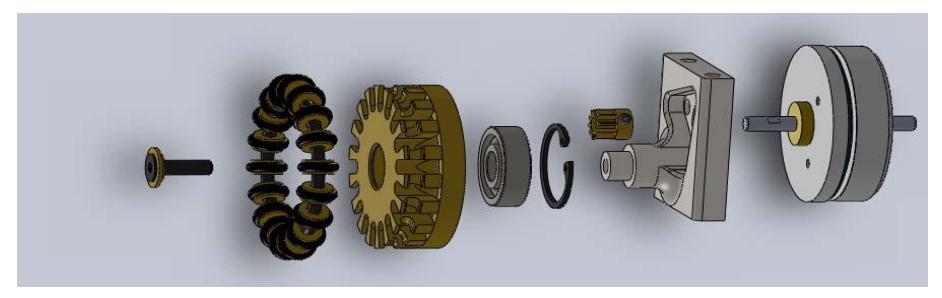
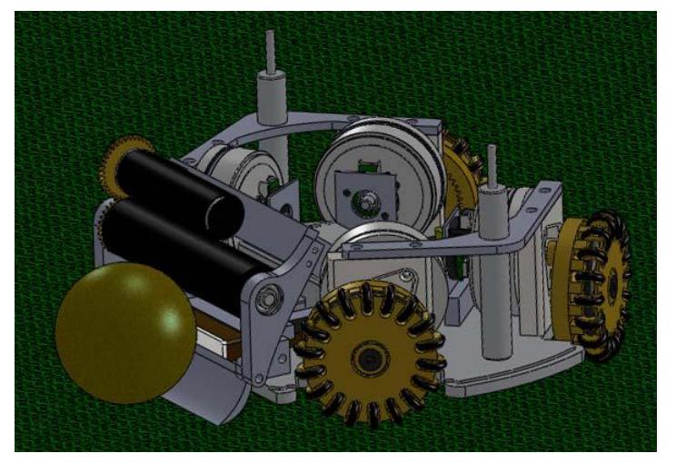
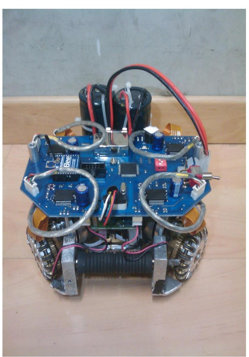
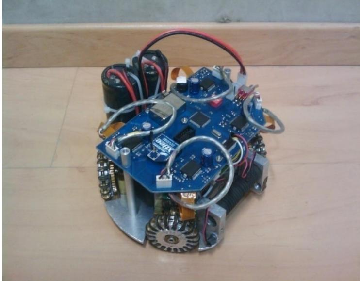
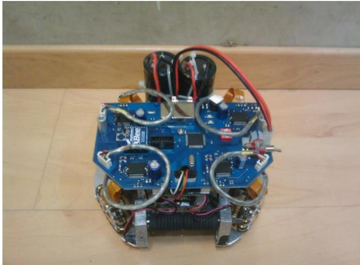
The robot's aluminum chassis is on four wheels. Each wheel is coupled toan EC-45-Flat brushless 30 watt motor via a inverse gear with a transmission ratio of 1:5. These Wheels are fully designed in one piece and there is no use of screw in the body of wheels. This feature causes more efficiency, more wheel life time and simplicity in design.
2.2 Kicking System
There is two flat solenoid that kicks the ball both for straight and chip kicks. The flat plunger is steel with the thickness of 4 mm. The kicking plunger is separated into two parts. The first part is magnet part which is made from steel and the second is made from material with no magnetic property, aluminium.
2.3 Spin- Back System
The Spin-Back module is driven by 15 watts Maxon EC16 with a transmission ratio of 2:1.
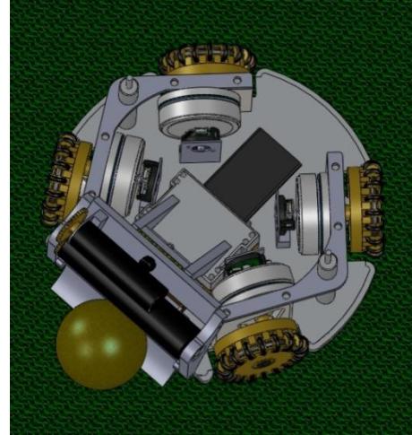
The robot's dimensions are 178mm diameter and 148mm height and it covers the ball 20%. It weighs about 2.5 kilograms.The 3D simulation models were created using SolidWorks.
Electrical System
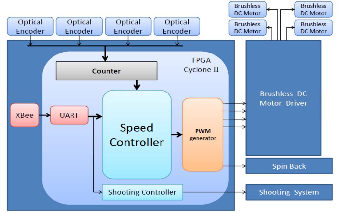
Our main circuit boards use FPGA to local feedback control loop. A PI algorithm drives all motors with asuitable PWM signal. Each EC-45 motor has an encoder which generates the feedback signalwith a maximum error rate of 1 degree on the wheel. The motors are driven using L6235 chip.[1]
The 802.15.4 standard is used for wireless communication which occurs in 2.40 to 2.48 GHzband in 12 channels at 250 Kbps using an XBee chip. These modules send and receive data tothe microcontroller using UART at a baud rate of 57600 bps. [2] Furthermore, the motor drive circuit, wireless communication part, and main control circuit are designed in a single board. The separatedshooting circuit board will connect to the main circuit.
3.1 Central Control
We use an cyclone II FPGA as the main controller togenerate all control signal for all parts.[3] It has a full duplex wireless communication to get the command packet from the AI computer at 50 times per second. Once the packets arrive, they have to be decoded andprocessed along with the data from four hall sensors, four encoders mounted withmotors, to generate signals to be sent to motordrivers, shooting system, and others.
3.2 Motor Driver
This task of the circuit is to drive 4 brushless DC motor for wheels and 1 brush DCmotor for dribbler.The motors are driven using L6235 chip. The L6235 is a DMOS fully integrated threephase motor driver with overcurrent protection.Realized in multipower-BCD technology, the devicecombines isolated DMOS Power Transistors withCMOS and bipolar circuits on the same chip.The device includes all the circuitry needed to drive athree-phase BLDC motor including: a three-phaseDMOS Bridge, a constant off time PWM Current Controllerand the decoding logic for single ended hallsensors that generates the required sequence for thepower stage.
3.3 Shooting System
There are two kickers: flatkick and chip kick. We develop the flat kick system to shoot at a velocity ofapproximately 8 m/s.The kicker board can charge two 2200 μF capacitors from 0V to 250Vin about 5 seconds with 2A average current.
Softwares
The robots software could simply be explained in two main sections. Visioning Software and the game play algorithms.
4.1 Vision
For the purpose of real time image processing and object recognition, wed use two cameras(The Stingray F‐046B/C's high resolution) andSSLvision Software. The communication between the vision software and the Game Management software(4.3.2) is using UDP multicast sockets therefore the visioning and game management processesare done on separate machines.
4.2 Game Play Strategy Algorithms
The game play strategy is organized into different functional levels to enable flexible and intelligent robot behavior.
4.2.1 Operational Functions
The functions of this section are categorized in three levels. Low, Medium and High Level Functions.
Low Level Functions
Low Level Functions are the robots basic behavior including: exactly addressed movements, stop, spin back On/Off, kick, chip kick. These functions are the latest ones ran in a process done by Decision Section (4.2.2) and a result of an appropriate command sent to the concerned circuit. The functions in higher levels are interpreted to the low levels in order to execute.
Medium Level Functions
Functions in this level are more general than low levels and mostly the common actions a robotdoes. For example one of these functions is "Potential Field Move". In this function a specificamount of electrical charge is assigned to all robots, the ball and special places on the play field. When a robot wants to go to a specific point it should move according to the electrical potential field rules to avoid making contact to other robots or losing the ball.
High Level Functions
These functions specify the current task of the robot and use the necessary medium levelfunctions. In fact high level functions are the robot's skills such as taking a defensive position,Goalkick, corner kick, passing the ball and so on.
An example of a moment when all the three level function are involved is when the DecisionSection (4.2.2) chooses the defensive state for a robot. Here the high level function "defense" will be executed and consequently the medium level function "potential field move" is run usingthe related low level functions like gotoxy, stop, spin back ….
4.2.2 Decision making Section
In this important section there are functions that determine the game's current status and predict the next and the result of this process will be assigning the proper high level function. The Inputs of this section besides the data coming from each robot on the wirelesscommunication are the data coming from the vision software and the referee.
4.3 GUI
The graphical user interface provides tools for testing and managing the robot system.
4.3.1 Game Simulator
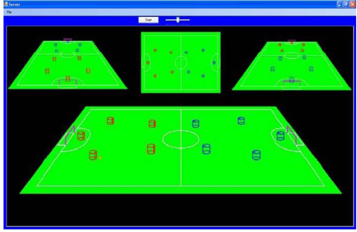
To test the Game Play Strategy Algorithms (4.2) without having two full robot teams and a play field a Game Simulator GUI is prepared. This way the Algorithm testing and error correction is done much easier regardless any physical and hardware problems and needs.
4.3.2 Game Manager
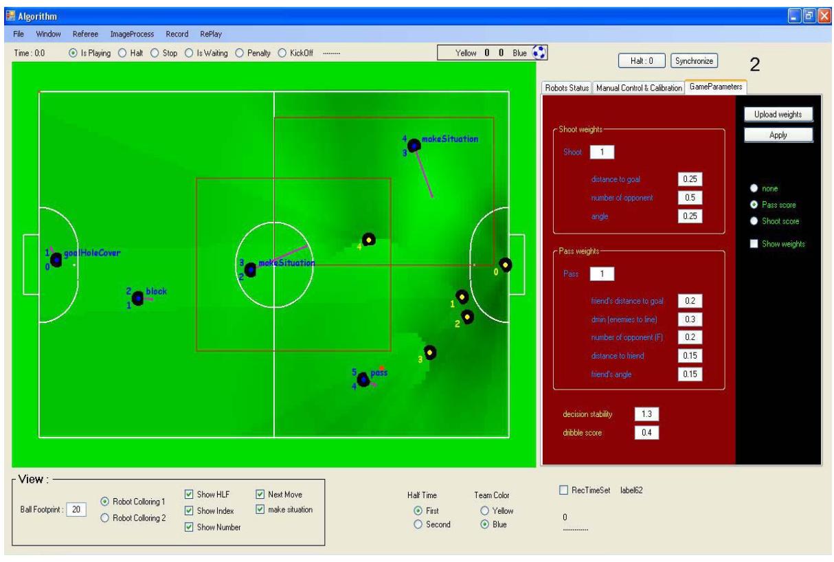
To monitor and control all robots in the game field Monitoring Software is programmed that willbe installed on the off board controlling system. The robots location and ID on the play field isreceived from the visioning software and simulated. In other word this software manages thegame play. A screenshot of this program is shown below.
References
- Vincenzo Marano, "L6235 THREE PHASE BRUSHLESS DC MOTOR DRIVER" Application Note,ST,2003.
- Drew Gislason, "ZigBee Wireless Networking" Newnes Press
- Altera, "Cyclone II Device Handbook"