Owaribito-CU 2010 Team Description
Yasunori NAGASAKA, Morihiko SAEKI, Takuya SOGO, Shoichi SHIBATA, Hironobu FUJIYOSHI, Takashi FUJII, Yoshiyuki TANAKA, Masafumi JYOUO, Takumi ADACHI, Masaki ITO, Kazuhiro SUZUKI, Kazuo TAUCHI, Chikara INUKAI, Alfred EBADE EFOSA
Faculty of Engineering, Chubu University, Japan
Abstract This paper describes the Owaribito-CU 2010 RoboCup small-size soccer robots, which are equipped with a holding device and a kicking device featuring a chip shot function. Four omniwheels provide omnidirectional motion. The paper focuses on improvements made this year: the development of a miniaturized kick device, improvements to the control circuit board, robot ID setting, and power supply efficiency.
1 Owaribito-CU 2010 Robots
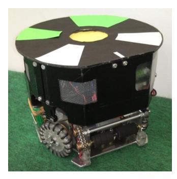
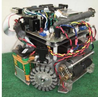
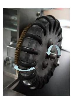
We have improved some points of our soccer robots for RoboCup 2010. These robots are equipped with a holding device and a kicking device. Our kicking device now has a chip shot function. Four omniwheels are used for the driving mechanism; they aid in realizing omnidirectional motion. The hardware specifications are listed in Table 1. The robot is shown in Figure 1.
Table 1. Hardware specifications of Owaribito-CU 2010 robots
| Specification | Value |
|---|---|
| Robot diameter | 141 mm |
| Robot height | 178 mm |
| Power consumption | 19 % |
| Weight | 2200 g |
| Frame | polycarbonate |
| Main computer | H8/3052F |
| Motor controllers | $dsPIC30F4012 \times 4$ |
| Radio | Futaba FRH-SD07T |
| Motors | Maxon Re-max $21 \times 4$ |
| Battery (NiMH) | GP2300Ni-MH AA size $\times$ 12 |
| Capacitor | $400 \text{ V}, 390 \mu\text{F}$ |
| Battery (Li-ion) | Lithium ion 3.7 V, 2000 mA |
1 Owaribito-CU 2010 Robots (continued)
From among the research that was worked on this year, this text describes the improvement of the kick device mechanism. It also involves the improvement of the circuit board, ID setting and power supply function.
2 Improvement of Kick Device
Figure 2 and Table 2 shows the external and the detailed data of an existing column type of kick device. The driving source of this kick device is a solenoid as well as most other robots of Robocup small-size robot league. The following were achieved in the last research work.
- The shot speed was adjusted to 10m/s
- The development of a chip kick device.
The aim of this project is the miniaturization of the kick device, without any reduction in the shot speed. Figure 2 shows the Column type kick device.
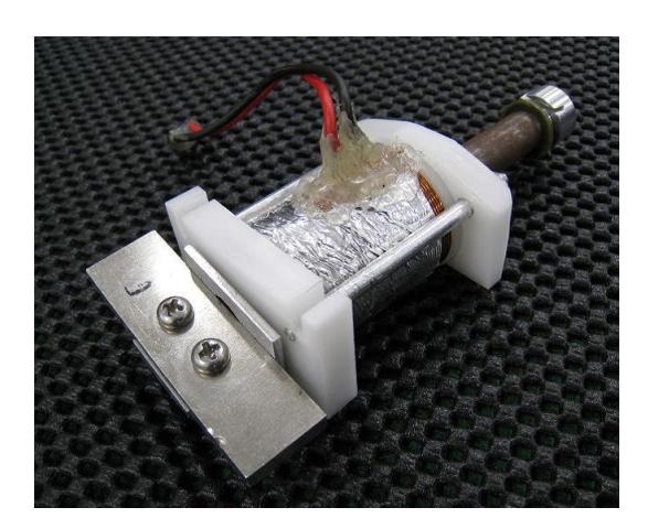
Table 2. Specifications of column type kick device
| Specification | Value |
|---|---|
| Stroke length [mm] | 40.0 |
| Diameter of enameled wire [mm] | 0.6 |
| Number of coil layers | 15 |
| Weight of solenoid [g] | 175 |
| Weight of head and core [g] | 75.7 |
| Average speed of ball [m/s] | 9.8 |
2.1 The Problems of Kick Device and Solutions
The problems of the current type of kick device are outlined below:
- We use the column type solenoid to use the flux of the magnetic induction efficiently. As a result when installing the kick device in the robot, wasteful space is being developed.
- Because the core is a column type, it is necessary to install a head that can hit the ball.
- Two solenoids for the shot and for the chip kick are meant to be installed; but due to space shortage it cannot be installed.
To solve the above-mentioned problems, a new kick device is developed in this research based on the following ideas.
- The bobbin is changed from the column type to the flat thin type by miniaturization.
- The core shape is made rectangular, the head and the core are the integral parts.
2.2 Design of The Kick Device
This is a design to make the bobbin shape a flat thin type from a past column type. The adequate values of diameter and the length of the enameled wire obtained for the last research are being used. Moreover when designing the device we have to bear in mind that the stroke length of the bobbin will be same as the column type which is 40mm. The material used for bobbin is polyacetal, Aluminum is used for the head (non magnetic part) and SS400 is used for the core part (magnetic substance). Figure 3 and Table 3 shows externals and the detailed data of completed kick device A.
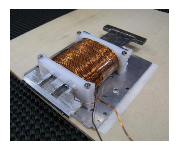
Table 3. The detailed data of kick device A
| Specification | Value |
|---|---|
| Stroke length [mm] | 40.0 |
| Diameter of enameled wire [mm] | 0.6 |
| Number of coil layers | 11 |
| Weight of solenoid [g] | 185 |
| Weight of head and core [g] | 65.0 |
2.3 Performance evaluation experiment of kick device
In this study, the speed of the ball is measured with a high speed camera (Figure 4). And the performance of the kick device is evaluated. The measuring method of the speed of the ball is outlined below:
- The ball which was struck by the kick device at 100mm interval passing between two lines was taken with a high speed camera
- It is possible for the high speed camera to take a maximum of 1200frames/sec. The number of frames is counted at 100mm intervals to estimate the ball speed.
- The speed of the ball can be calculated from the number of the frames. The velocity is assumed to be v (m/s) and the number of frame is assumed to be x; below is an expression used for the calculation.
$$v = \frac{120}{x} [\text{m/s}]$$
Below is the specification of the device (figure 4) which was used in the experiment:
- High speed camera: CASIO EX-F1
- A charge circuit(Capacitor: 200V 3700uF, Switching use MOS-FET: 650V 47A, Power supply: Lithium ion battery, 11.1V, 1100mAh)
- Charge control board: H8 microcomputer
- Ball: diameter:42.8 mm weight:46 g
- Using a wood of constant thickness or an iron plate for adjustment of the height
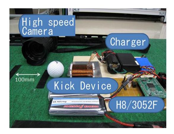
Table 4. Result of the measurement of kick device A
| Iteration | Ball speed [m/s] |
|---|---|
| 1 | 8.76 |
| 2 | 8.7 |
| 3 | 8.7 |
| 4 | 9.16 |
| 5 | 8.82 |
| 6 | 8.96 |
| 7 | 8.82 |
| 8 | 9.09 |
| 9 | 9.16 |
| 10 | 8.82 |
| Average | 8.9 |
Table 4 shows the result of the measurement of kick device A. The height of the run(RBI) from the floor and the distance between the ball and the head tip is evaluated beforehand and the best is used. For the kick device A the height of the runs is 21mm, and the distance between the head tip and ball is 30mm.
2.4 Improvement of kick device
Because the average ball speed of the kick device A falls below the average speed of the column type; an improved kick device B was made. The modification from the kick device A, the stroke length is made to the size limit that can be installed in the robot. It is expected that the best stroke length changes because it is improved from the column type to a flat thin type. From the last research work it was observed that the speed of the ball changes with the stroke length. Moreover , there is an advantage of reducing the number of coils by making the bobbin thinner and increasing the space of the second solenoid. Figure 5 and Table 5 shows externals and the detailed data of completed kick device B.
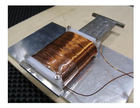
Table 5. The detailed data of kick device B
| Specification | Value |
|---|---|
| Stroke length [mm] | 52.0 |
| Diameter of enameled wire [mm] | 0.6 |
| Number of coil layers | 9 |
| Weight of solenoid [g] | 170 |
| Weight of head and core [g] | 74.8 |
Table 6. Result of the measurement of kick device B
| Iteration | Ball speed [m/s] |
|---|---|
| 1 | 9.52 |
| 2 | 10.00 |
| 3 | 10.34 |
| 4 | 9.52 |
| 5 | 10.00 |
| 6 | 10.00 |
| 7 | 9.68 |
| 8 | 10.26 |
| 9 | 10.08 |
| 10 | 10.34 |
| Average | 9.98 |
Table 6 shows the result of the measurement of kick device B. The result of the height of the run(RBI) from the floor and the distance between the ball and the head tip is evaluated beforehand, and similar values of kick device A are used about the height and the distance.
2.5 Examination of the combination of bobbin and core
In an attempt of trying the check out the effect of the core length on the ball speed, the combination of bobbin and core that was worked on is changed and an experiment is done.
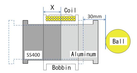
Combination experiment 1 In the bobbin of kick device A, a long core of kick device B is used. It is assumed that the distance between the head at its lowest position and the ball is always 30mm, there is a fixed height between the run and the floor; the distance the aluminum core, joined metal part and the coil point is assumed to be X. The fastest speed of the ball with respect to the distance X is checked. Figure 6 shows the simplified schematic of the combination experiment. The square dotted line shows the core when heads was at its lowest position. Table 7 represents the relationship of the joined parts of the core and the coil initial position with respect to the distance and speed. From the combination experiment 1, the ball speed changes with respect to the distance X. The ball speed is kept under the coil insertion ratio of 10%, if it is more than 10% it will reduce the ball speed. Furthermore for the kick device A bobbin, if the core length become longer, the ball speed can be more than 10m/s.
Table 7. Result of combination experiment 1
| X [mm] | Ball speed [m/s] |
|---|---|
| 0 | 10.34 |
| 5 | 10.34 |
| 10 | 9.52 |
| 15 | 8.45 |
2.5 Examination of the combination of bobbin and core (continued)
Combination experiment 2 In the bobbin of kick device B, a short core of kick device A is used. The other procedure is same with combination experiment 1. The relationship between the joined core and the coil initial position with respect to the distance and the velocity(speed) is shown in table 8. The distinction between the combination experiment 2 and 1 is; for the combination experiment 2 there is a gradual decrease of the ball speed with respect to the distance X. Moreover, it is expected that kick device B can strike at a speed of 9.5m/s even if aluminum that is the nonmagnetic material in the core is shortened by 15mm. The kick device B is not only thin; but it is possible to make closer to the kick device A in total length.
Table 8. Result of combination experiment 2
| X [mm] | Ball speed [m/s] |
|---|---|
| 0 | 8.28 |
| 5 | 8.11 |
| 10 | 7.69 |
| 15 | 7.5 |
| 20 | 6.86 |
2.6 Summary
From the experiment the combination of the bobbin of the kick device B and the long core resulted to a ball speed of 10m/s; and it has the performance similar to the kick device of the column type. Comparing from the miniaturization point of view, the kick device A is short; while the kick device B is very thin. Kick device B is suitable for stacking two solenoids. It can be said that miniaturizing was achieved without a drop in performance of the kick device B. In this experiment, only little experinment was done on the size of the SS400 core (magnetic), and the relationship between the coil length with respect to the ball velocity (speed). Our future task is for further optimization.
3 Improvement of the control circuit board
In this year, 3 points was examined regarding the circuit board improvement; these are improvement of the efficiency of power supply circuit, sharing of robot ID setting and DIP switch, and lastly the standardization of circuit pattern of control circuit.
3.1 Improving the Efficiency of the Power Supply Circuit
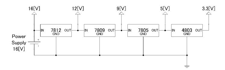
The voltage supplied to the parts on the present board are 16[V], 9[V], 5[V] and 3.3[V]. So far the power supply voltage (step down voltage) has been done with multiple use of three-terminal regulators. The respective voltage was supplied at one power source.
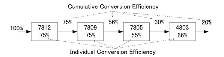
However, because of the efficiency of these three-terminal regulators, the conversion efficiency is very poor for the 3.3V terminal. The use of multiple poor efficient three-terminal regulators could have caused a gross inefficiency. H8-3052F microcomputer only use the 9[V]. Since H8-3052F can work with the range of voltage between 6.5[V] and 9[V], during the step down of voltage from 16[V] to 9[V], 7812 and 7809 of the three-terminal regulator are removed to simplify and improve the efficiency; and two power source is integrated. The 16 [V] power source is for the motor drive, and the other power source for other operations. 7.4V of two Li-Ion cells were used as the power source.
3.2 Sharing Robot ID Information with DIP Switchs
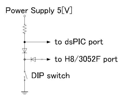
Our curent circuit board uses four dsPICs and one H8 microcomputer; the dsPIC controls the rotation of each motor, while the peripherals such as the charging circuits and the infrared ray sensors are controlled by the H8 microcomputer. There is the problem of the peripherals being controlled by completely different circuit; because there is an interference between the power supply and the radio signal of the circuit. To improve this situation, the DIP switchs for setting the Robot ID was shared between the circuits related to dsPIC and H8 microcomputer. Robot ID is a number that can be used to recognize robot during a competition when there are multiple robots. The numbers are usually up to 5. For the input of this information, because there is usually a problem of converting from binary to denary, DIP switch was provided. However in order for there to be same input figure without any kind of data miss reduced component count and typographical error, the data needed to be shared.
Firstly, the method of input of dsPIC was considered. Three input terminals were provided for the dsPIC, and the input was done in binary numbers. The input values where entered as [1] for 0[V] and [0] for 5[V]. Also for the H8 microcomputer five input terminals are provided and it is entered in denary number, the input values where entered as [1] for [opening] and [0] for [GND] respectively. In order to unify these two input methods, firstly the three input terminals are chosen and it was entered in binary. To keep compatibility for current circuit, next parts were added to the interface for ID setting (Figure 9).
3.3 Standardization of the wiring pattern of control circuit
The DC motor is used to move the robot. The control unit of a motor consists of the motor driver and the dsPIC which performs the control operations. In order to distinguish between the controls of each motor, information with two input terminals of dsPIC is used. Outside that the other peripheral circuits are same. The function of the circuit is same, but the wiring pattern is different on the board, then it is very difficult to check the wiring condition during the inspection. For a unified and improved maintenance, the standardized wiring pattern that can be used in any part was made.
3.4 Summary
In this improvement, the board is more efficient and easy to use compare to the board used in the past. However in this case the size of board is slightly larger than in the past. In the next project, we will check the current in each wire, and replace the parts to proper parts and try to miniaturize the board.
4 Conclusion
We have described the specifications of our 2010 version robots. Furthermore, we have described several topics from the developments of this year. The kick device was examined, also the improvement of the control circuit, ID setting for proper identification and power supply board was demonstrated. The aim was also to make a more durable circuit board.