Parsian (Amirkabir Univ. Of Technology Robocup Small Size Team) Team Description for Robocup 2010
Valiallah Monajjemi, Seyed Farokh Atashzar, Vahid Mehrabi, Mohammad Mehdi Nabi, Ehsan Omidi, Ali Pahlavani, Seyed Saeed Poorjandaghi, Erfan Sheikhi, Ali Koochakzadeh, Hamid Ghaednia, S. Mehdi Mohaimanian Pour, Arash Behmand, Hamed Rastgar, Mohammadreza Arabi, Mina Nouredanesh
Electrical Engineering Department, Amirkabir Univ. Of Technology (Tehran Polytechnic), 424 Hafez Ave. Tehran, Iran
Abstract This paper describes the current technical state of Parsian small size soccer robots team for participating in RoboCup 2010 competitions. The robots' hardware as well as the developed software tools will be discussed in detail. It also introduces some new ideas for improving hardware and software of a small size soccer robots team.
1 Introduction
"Parsian" SSL team is a research project, started in 2005, coordinated by Electrical Engineering Department of Amirkabir University of Technology. Parsian has been active in field of small size soccer robots since then. Our SSL team has been qualified for RoboCup competitions since 2006 and participated in 2008 and 2009 competitions.
After RoboCup 2008 competitions we started a total redesign both in robots' hardware and software. Currently we are working to improve our robot's mechanical and electrical systems as well as developing new control/AI algorithms and software utilities.
In this paper we first introduce our robots' hardware. Our mechanical design will be discussed In section 2.1 and our electrical design will be covered in section 2.2. Our vision system will be discussed briefly in section 3. Section 4 explains our software framework including high level planning algorithm, low level control algorithms and our new 3D simulator.
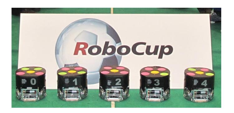
2 The Robot Hardware
(see subsections 2.1 and 2.2)
2.1 Mechanical Design
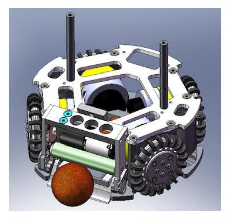
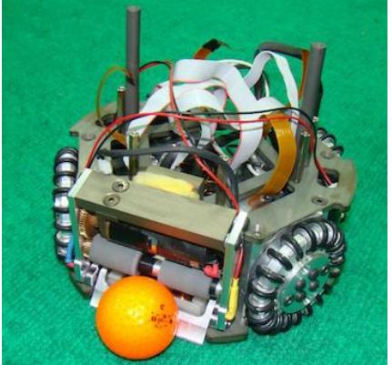
In this section we introduce our new mechanical design which we have been working on since early 2009. Our new design was used in Robocup 2009 for the first time, however it suffered from some minor issues. Currently we are working to improve the design as well as optimizing it. Our new design (Figure 2) has been developed using various CAD/CAM and real-time simulation tools. Most of our robot's mechanical parts are produced using computer numerical controlled machine tools to increase precision. Our robot's physical properties are as follows:
Robot Diameter 180 mm Robot Height 149 mm Ball Coverage 19 % Max Linear Velocity 2.8 m/s Weight 3.6 kg
Driving System
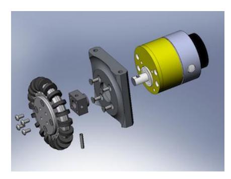
Our robot is a four wheel omni directional robot. Each wheel is driven by a Maxon EC45 flat 30 watts motor attached to a Maxon GS45 1:4.7 gear head. The wheel itself is a 68mm diameter omni wheel with 20 sub-wheels. The wheel is made of aluminum. A digital tachometer is attached to each motor to provide speed feedback. Figure 3(a) shows the driving system in detail.
One of the problems we faced in our initial design of the robots was that the robots were unable to move left or right in a straight line even in low speeds. After simulation and analysis, the high friction between the sub-wheels and the ground found to be the reason. The problem solved by increasing the number and diameter of sub-wheels.
The Main Structure
The robot's main structure is made of aluminum alloy 7075 T6 to keep the robot light and robust. To reinforce sensitive parts like dribbling system's holders, we used CK45 steel. As our driving mechanism is a long structure, it was a design challenge to place four driving system and kicking devices on the chassis and also not exceeding valid dimensions. We accomplished this task by optimizing the dimensions of the kicking solenoids and motor holders. We also designed a coupling system to connect the wheels to the motors directly. To prevent short circuit between electrical components and to reduce erosions, all parts are harden anodized.
Direct/Chip Kick
We optimized our direct kicking system this year to consume less space without loosing its efficiency. A cylindrical solenoid surrounding a plunger builds up the whole kicking system. The plunger itself consists of a magnetic bar, a paramagnetic bar and the plunger head. The magnetic and the paramagnetic bars are both 10mm rods which are thread fastened. The bars' size and weight are optimized to transfer maximum energy to the ball. The challenge we faced here was the shape of the plunger head which lacked sufficient strength during power transmission to the ball. We are still working to reach the optimal shape.
The chip kicking system is similar to direct kicking except that it uses a flat solenoid with polyamide core. A special mechanism designed to transduce the linear motion to rotational motion. This system can throw the ball up to 60cm height and 5-6m long.
Dribbling and Suspension System
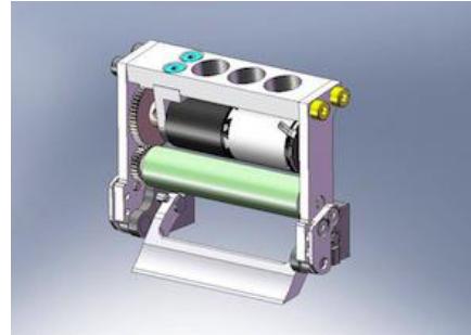
In our current design we use Maxon A-Max22 DC motors (6 Watts) with GP22 1:3.8 gear heads for spinning the ball. With help of two external gears with ratio of 2.5:1 the spinner can reach the speed of 4500 RPM. The mentioned actuator is not powerful enough for a successful ball manipulation, so we are currently working on a new design to use Maxon EC16 motors (15 Watts). In order to effectively receive passes and intercept moving balls we designed a special kind of suspension system for the dribbling device. The whole system is depicted in figure 3(b).
2.2 Electrical Design
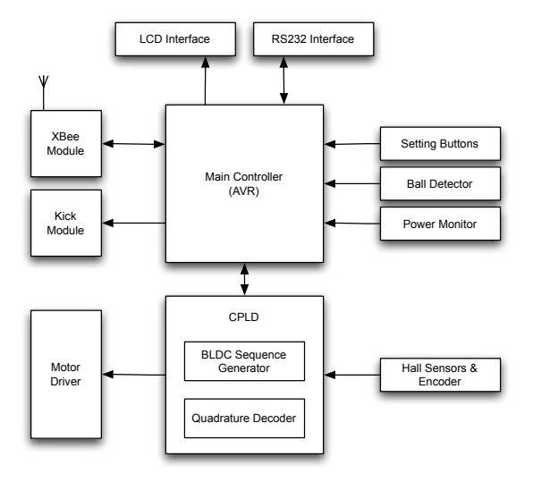
The electrical system consists of two electronic boards (the main board the kick module), infrared ball detectors, capacitors and batteries.
Wireless Communication
The command packets sent by the remote host PC is received by Digi's XBee OEM RF Module. The XBee modules are designed to meet IEEE 802.15.4 (ZigBee) standard. They consume very low power and operate within the 2.4 GHZ frequency band. This module is fast and easy to configure. It can communicate at baud rates up to 115200bps.
The received command packets are 30 bytes long byte streams. The packet contains the desired velocity for each motor, the kick/chip desired speed and permission and spinner activation command. The XBee module operates in half duplex mode. Once in a second this module sends back some data such as batteries' and motors' status back to remote host PC.
Each robot is powered by three 2-Cell high power 2000mAH Lithium Polymer batteries.
Motor Driver
The BLDC driver unit consists of a XC95144CPLD as a main controller and four power driver stage. The CPLD receives the hall sensors feedback and generates the proper control sequence for each motor. Six FDS4410 N-Channel Power MOSFETs driven by IR2130 three phase drivers form the power driver stage for each motor.
PID Speed Control
The CPLD unit also counts the quadrature encoder signals and calculates each motor speed. This data is sent to the board's main processing unit which is an ATMEGA2560 micro-controller. The desired velocity command received from the XBee module and the current motor speed are fed into a soft PID controller to generate the control commands for each motor. The resulting commands are sent back to the CPLD unit.
Kick Module
Our kick module has been under active development since last year. The current design is based on a DC-DC Boost Convertor circuit. It can charge two 2200uF 100V capacitors (connected in parallels) up to 195 volts in 5.5 seconds. To discharge the stored energy a MOSFET high power switch with a RCD snubber is used.
3 Vision System
Our vision hardware consists of two AVT Marlin F046C cameras which can capture images with resolution of 780x580 pixels at speed of 45fps. We use these cameras in YUV color space mode with ROI enabled. For a wider view of the field we use 4.5mm wide lenses. Images captured from cameras are transmitted through firewire cables to IEEE1394 PCI-cards and then fed into to the SSL shared vision system's software (SSL-Vision) [1] for processing.
4 Planner
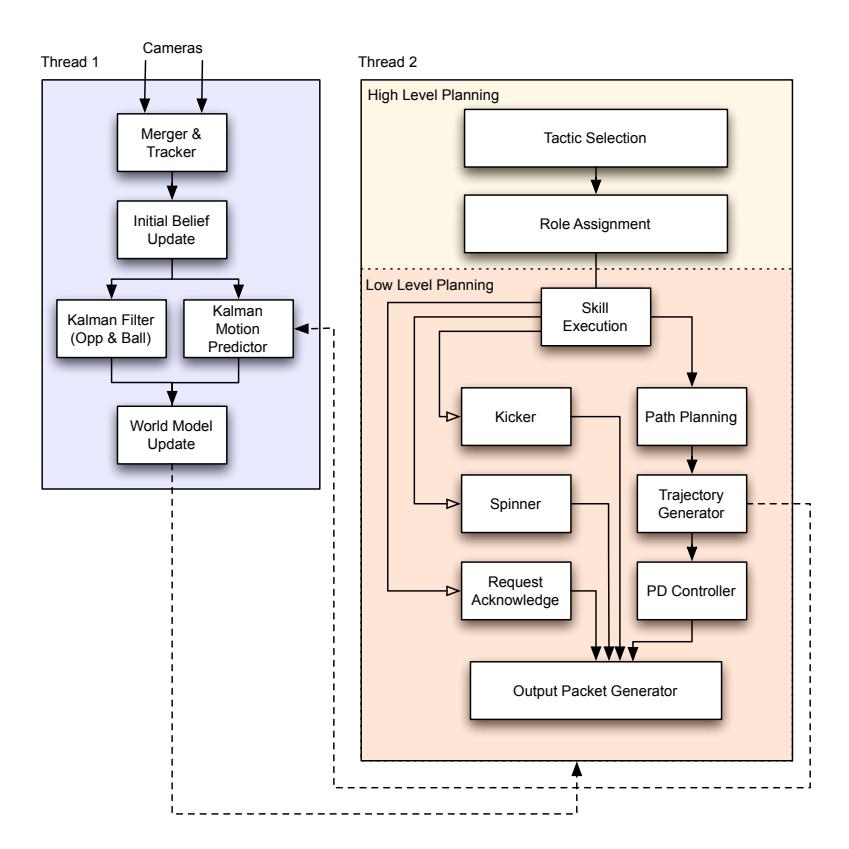
An overview of our planner is demonstrated in figure 5. As shown, the second thread or the decision making thread is executed independently from the World Model update thread, this is mostly because the vision packets from each camera are not received simultaneously. Using the information abstracted in World Model, the execution starts from the coach layer and hierarchically goes down to low level skills. At the end of each cycle a packet containing robots' commands is transmitted through wireless communication.
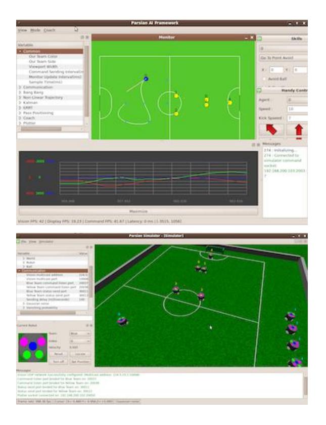
The planner framework is written in C++ using Qt framework[2]. This software runs on an Ubuntu Linux based PC (Figure 7(a)). Through the rest of this section, we will describe some of researches and achievements implemented in our planning and control layer.
4.1 High Level Planning
At the beginning of each planning cycle, the coach layer chooses one of the predefined tactics based on current game state and referee's signal. This tactic is then broken down into some Roles which will be then assigned to agents. Our approach is mostly motivated by STP framework [3].
Choosing a tactic (i.e heavy defend, 3 agent attack, ... ) is based on its success rate. Each tactic's success rate is evaluated using its success/failure after several executions during the match. One method that can help us optimize selection weights is "Threshoded Reward" Markov Decision Process (MDP) [4], which we are currently working to implement it into our framework.
4.2 Motion Planning
A precise, fast and robust robot motion is a task that greatly affects the performance of the whole team. A proper motion planner depends on these three steps:
- An accurate estimation of position and velocity
- A safe path to move along
- A trajectory planner which considers robot dynamics
In our motion planner, these three steps respectively are correspondent to Kalman filter, ERRT path planing and Bang Bang trajectory generator.
Kalman Filter
As mentioned, in the designed motion planner a Kalman filter is utilized as the main part of the motion profile predictor, which estimates the position, velocity and acceleration of the robots and the ball, utilizing some noisy, delayed measurements. In order to enhance the estimation of our team robots' state vector we developed a new motion predictor. The pre-assigned velocity commands (which were generated by the trajectory planner in the previous sample time) are employed as additional measurements. This improvement leads to considerable enhancement in the motion predictor.
Path Planing
Finding a safe trajectory (free of obstacles) is the first step of leading a robot to the desired position. After implementing some conventional path planning algorithms we found out that most of them are not applicable in field of robot soccer. That is mostly because of the high robots' speed and sudden velocity change. We found that Execution extended Rapidly-exploring Random Trees (ERRT) algorithm has a better performance compared to other path planners in such conditions [5][6].
This year we improved the ERRT algorithm to perform a better search in the configuration space and bringing more dynamics into account.
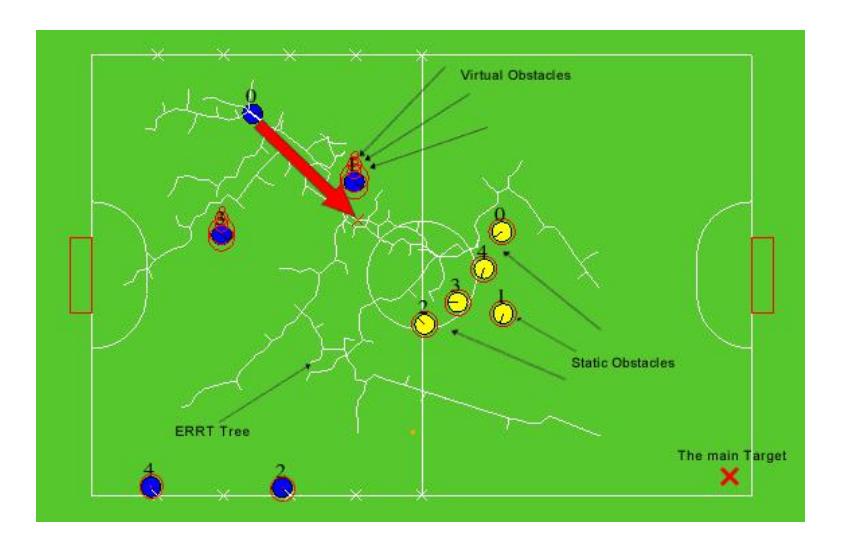
To perform a better search in the configuration space, the step-size (length of tree's branches) varies proportionally to the distance between the current state (node in tree) and the goal state. While generating the path, the more the nodes are farther from the goal, the bigger the step size would be. As a result the tree narrows toward the goal state.
To bring more dynamics into the algorithm, the algorithm adds a series of dummy obstacles in the moving obstacle's motion direction which causes the tree not to cross the obstacle's motion direction. The size of dummy obstacles and the intra-distances between them varies dynamically with the absolute velocity of the obstacle. Figure 6 illustrates these modifications.
Trajectory Generator
The target specified for the robot by the path planner section is then fed into a conventional bang-bang trajectory generator. This planner tries to achieve the most applicable speed and decelerate the robot in the appropriate time to reach the target in an optimized time. In addition to above, in the employed trajectory planner, a nonlinear speed controller inside a boundary around the target is implemented, to reduce and damp the undesired robots oscillations. The duty of the aforementioned bang-bang trajectory planner is to generate the desired velocity of the robots, afterward a PD-controller is employed in order to minimize the navigation error.
Curve Tracking
Curve Tracking is a new skill we implemented this year to make the robot move on a pre-specified curve by keeping its velocity vector tangent to the curve. The curve is defined by two mathematical functions, x(t) and y(t) which specify a point's coordinations on the curve for a given t value. As an example x(t) = t , y(t) = t 2 represents a parabola equation y = x 2 .
In this skill, robot is forced to keep a specified angle with the curve's tangent direction (φ). Moving along the curve, robot should take an angular velocity proportional to its tangential velocity in order to keep its heading direction close to φ.
In this approach, A one dimensional bang bang trajectory generator is employed on the curved path instead of it's default path (straight line). Therefore the curve's length is needed. This length is calculated using equation 1.
$$L = \int \sqrt{1 + \mathbf{r'}(t)^2} dt$$
In above equation, r(t) is the vector function which represents the curve. r'(t) and r''(t) represent the first and second derivations of r(t) respectively.
$$\mathbf{r}(t) = x(t)\hat{\mathbf{i}} + y(t)\hat{\mathbf{j}}$$
The output of the 1D trajectory generator is the robot tangent velocity (v). The angular velocity is calculated then from equation 3.
$$w = \frac{v}{R}$$
In above equation, R is the radius of local circle fitted to the curve. The radius of this circle is calculated using equation 4.
$$R = \frac{|\boldsymbol{r'}(t)|^3}{|\boldsymbol{r'}(t) \times \boldsymbol{r''}(t)|}$$
t is calculated in a way that equation 2 represents the nearest point on the curve to the robot's current position. A proportional controller is used to keep the robot's position on the curve and adjust its direction if needed. Our curve tracker supports any analytical function such as polynomials, circles, ellipses, and cubic splines.
4.3 3D Simulator
This year we designed a brand new 3D dynamic simulator for the field of RoboCup SSL. This simulator (named "grSim") has many features which reduces the differences between the real dynamic world and the simulated world.
grSim has several new features in comparison with our old simulator [7]. Opposed to the old one where the robots were modeled as solid boxes, grSim models robots similar to their real physical shape, each robot consists of four velocity controlled wheels and a kicker. The torques generated by the controllers, are applied to the wheels and cause the robots to moves.
Similar to real world, there is a friction between the wheels and the ground surface. Two kinds of friction coefficients are defined for each wheel, tangent and normal. By choosing the normal coefficient much lower than the tangent one, the wheel behaves like a real omni directional wheel. In this way, there's no need to include sub-wheels in the wheel's physical model, which decreases the model complexity and increases the simulation performance.
Some of grSim's features are listed below.
- A rich graphical user interface that eases robots and ball manipulation
- SSL-Vision compatible localization data output with custom Gaussian noise and delay
- Realtime configuration using VarTypes[8] library (Physical properties, Network configurations, etc)
- Flexible input layer using XML Based protocol definition
grSim (like our AI framework) is written in C++ using Qt framework and is currently under active development. We believe that grSim can help other SSL teams with its rich features. Our plan is to release grSim to public in near future. Figure 7(b) shows a screenshot of the simulator.
References
- Stefan Zickler, Tim Laue, Oliver Birbach, Mahisorn Wongphati, and Manuela Veloso. SSL-vision: The shared vision system for the RoboCup Small Size League. In Jacky Baltes, Michail G. Lagoudakis, Tadashi Naruse, and Saeed Shiry, editors, RoboCup 2009: Robot Soccer World Cup XIII, Lecture Notes in Artificial Intelligence. Springer, to appear in 2010.
- Nokia Inc. Qt A cross-platform application and UI framework, 2010. [accessed January, 2010].
- B. Browning, J. Bruce, M. Bowling, and M. Veloso. STP: Skills, tactics, and plays for multi-robot control in adversarial environments. Proceedings of the Institution of Mechanical Engineers, Part I: Journal of Systems and Control Engineering, 219(1):33–52, 2005.
- C. McMillen and M. Veloso. Thresholded rewards: Acting optimally in timed, zerosum games. In Proceedings of the national conference on artificial intelligence, volume 22, page 1250. Menlo Park, CA; Cambridge, MA; London; AAAI Press; MIT Press; 1999, 2007.
- J.R. Bruce and M.M. Veloso. Safe multirobot navigation within dynamics constraints. Proceedings-IEEE, 94(7):1398, 2006.
- J. Bruce and M.M. Veloso. Real-time randomized path planning for robot navigation. Lecture Notes in Computer Science, pages 288–295, 2003.
- V Monajjemi, H Ghaednia, S Khoshbakht, M Rohani, V Mehrabi, A Pahlavani, E Omidi, M Shahbazi, F Atashzar, and A Amir Ghiasvand. Parsian - amirkabir university of technology robocup small size soccer team. Team Description Paper for RoboCup 2009, Feb 2009.
- S Zickler. Vartypes A feature-rich, object-oriented framework for managing variables in c++ / qt4., 2010. [accessed January, 2010].