RFC Cambridge
Alexei Colin, Svilen Kanev, David Robinson, Rui Jin, Jesse Thornburg, Benjamin Johnson, Aaron Ramirez, Julie Henion, Scott Crouch, Daniel Lynch, Julie Xie, Jesse Yang, Marcel Thomas, Evelyn Park
Massachusetts Institute of Technology, Cambridge, MA 02139, USA; Harvard University, Cambridge, MA 02138, USA
Abstract After hosting the US Open and competing in the international competition last year, RFC Cambridge has adopted a new way of developing and testing software. Our members have also designed and implemented new hardware features. In our team description paper we will explain the most relevant components of our current system, changes we have made to make our system more robust, and our most innovative developments since last year.
1 Team Outline
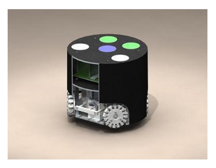
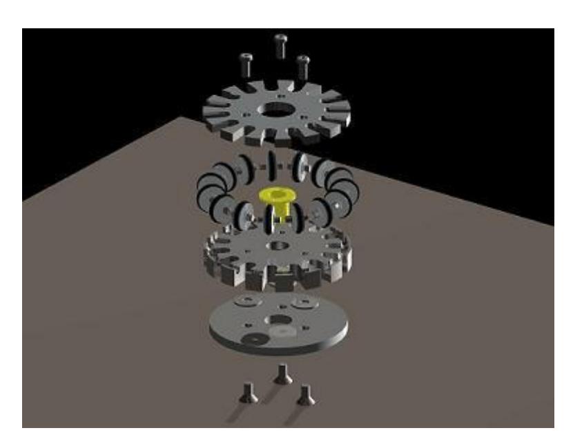
RFC Cambridge is a joint Harvard-MIT team in its fifth year of competition in RoboCup. We participated in the international Robocup competition in 2006, 2007and 2009, as well as the US Open in 2008 and 2009. We have learned a lot over the past years and have been working to upgrade our systems to be competitive in this year's competition. We are led by Benjamin Johnson (Electrical Engineering at MIT, class of 2010) and Julie Henion (Mechanical Engineering at MIT, class of 2011) with the help of an executive board of 6 other members. We are the only Harvard-MIT organization, one of few engineering clubs at Harvard, and one of the few completely undergraduate-led RoboCup teams. With a solid foundation for a mechanical system from last year, the mechanical team focused on increasing functionality and adding new features, such as a chip kicker and a break-beam ball detector. The computer science subgroup has redesigned a major portion of our system – including the transition to SSL-vision, a completely new playbook and lots of improvements in terms of stability performance. The mechanical engineering subgroup focused on building a flexible working model based on research of existing technologies that could be innovated in later years. The robots have 4 wheels in a butterfly formation and are powered by a brushless motor drive system with customized omni-directional wheels. Our robot also has a rubber-coated dribbler and one electro-magnetic solenoid for planar kicking. The current height of the robot is 15cm, the maximum diameter of the Robots projection to the ground is 18cm, and the maximum percentage of ball coverage is approximately 19.
2 Electrical Engineering Improvements
2.1 Reliability
One of the largest problems in previous years was reliability of our boards. They were often "flakey." that is they would temporarily cease working or break, and as far as we could tell it was for non-systemic reasons. The most common symptom of this was a PIC microcontroller appearing to be broken, but upon a power reset it would act normally. Upon further investigation it was determined many of these problems were probably caused by noise on the boards due to poor PCB layout. This past year all the boars were relayed out with special attention to decreasing and compensating for noise. This new version of the boards does not exhibit any of the same problems and the robots are able to drive much better.
2.2 Kicker board
The circuit board to charge and discharge the kicking capacitors was redesigned. Like the old design, the new one incorporates a flyback converter circuit to charge the capacitors. Power is drawn from the batteries into the primary side of a power transformer. After the primary side current has reached a pre-determined threshold (about 4 Amps), a MOSFET is switched off on the primary side. Energy is transferred to the secondary side and charges the capacitors. The MOSFET is controlled by a newly incorporated chip, the LT3750, which is specially designed for flyback converter capacitor charging topologies unlike the chip in the previous board design. All the components in this circuit have also been upgraded to accommodate higher currents, thus resulting in a faster capacitor charge time than was possible in the previous board version.
The method of discharging the capacitors has not been changed. Functionality still exists for programmatically-initiated discharge of the capacitors through a power resistor, as well as for manual switch-initiated discharge through the power resistor. For kicking, an SCR still controls the passage of current from the capacitors through the kicker solenoid to ground. However, an extra SCR-controlled discharge channel was added to support chip kicking. This channel includes the solenoid on the chip kicker instead of the one on the regular kicker.
2.3 Motor Drivers
As mentioned previously the biggest improvement of the motor drivers was decreasing noise in the electronics with a new PCB layout. We also discovered that the original commutation code for the brushless motors was buggy, one of the commutation sequences was wrong causing motors to have a tendency to be stronger in one direction than another. This coupled with greater mechanical consistency of the wheels has lead to much better driving robots.
3 Control Improvements
In previous years, reliable motion control was holding us back to a great extent. Our previous control subsystem relied on two levels of feedback – on-board single-wheel velocity control, for which the feedback elements are optical encoders, and whole robot position control running on the software system through the camera loop. Our high-level controller was an ad-hoc solution relying on the fact that sooner or later, a position PID loop will converge on the desired values. Because of that, it was difficult to calibrate, not reliable enough and slight changes in the hardware (for example, decreased battery voltage) were having a substantial effect. To deal with these, we assembled a control subteam and took the time to carefully model the robot and come up with a controller that was aware of that model.
For the first time we fully modeled the robot from the motors up. The state-space controller developed however was based on a continuous time approximation, which did not work as well as hoped due to a lower (15Hz) camera frame rate during initial testing. This controller was also designed with out accounting for any onboard speed control. Despite this when combined with an onboard PID controller that includes a feedforward term the robots drive observably better then previous years. This transition, coupled with increased electrical and mechanical reliability, enabled us to drive steadily at speeds, twice higher than our previous design.
In the coming weeks we plan to more rigorously integrate the two control systems. We also now with the ability to have two way communication over the radios with the robots, can better observe what the robots are doing. This will help as we seek to define metrics to evaluate both the tuning and different controllers we hope to develop.
4 Software Improvements
4.1 Vision System
The largest change in our vision infrastructure was the transition to SSL-Vision. From our experience, this was a good step forward mainly because of the much simpler calibration routines and the increased reliability. The transition to SSL-Vision coincided with changes to the code that merges the input from both cameras. Our new algorithm uses the timestamps from the SSL-Vision image packets to perform smarter merging based on how recent an incoming packet is. Because of a large amount of performance improvements in the general system, we now manage to run the vision loop at 30Hz and use the incoming information at that framerate. We are still experiencing some performance issues in the merging zone and are currently working on a better parallelizable solution for merging. After that, we are hoping to be able to run stable at 60Hz. To further improve that in the long run, we are planning to use a Kalman filter for interpolating between frames.
4.2 Rewritten playbook & Simulator
From past experience, our plays for most game states had been really underdeveloped. By watching a lot of real Robocup games, we understood how critical plays for free kicks and stopped game were for team performance, especially because the game in the small-size is so fast paced that a large portion of the time is spent in these states. We developed better games for these particular states and improved the general attack and defense plays. We also focused on the transition between different game states and made sure that in general our new plays transitioned smoothly into each other.
While working on the play system, we discovered that our current play language isn't descriptive enough to include all our intended games. We are in the progress of developing it further to allow plays that include state.
Most of the work on plays was done in simulation. We have been constantly working on improving our simulation environment. We've taken a modular approach there that allows us to easily switch between simulation and the real world for different components of the system. We are also working on an automatic referee in simulation mode, so that whole process can be fully autonomous.
4.3 Performance improvements
Since the start of the team, our codebase was constantly growing. This greatly increased complexity in debugging, writing code, and getting new members involved. Furthermore, support for some legacy methods turned out to be a serious performance bottleneck. We stepped back and did major refactoring and performance evaluation of our software system.
An example of the issues we ran into is the drawing in our GUI. Because of the two cameras, our drawing code was multithreaded and was using regular Windows GDI calls. However, this weren't cached by the OS and also didn't seem to parallelize well, which was a huge performance bottleneck and limited the throughput of our whole system. We solved the issue by caching the drawing calls and running the drawing code on the GPU using OpenGL.
By similar techniques, we managed to stabilize our AI loop, so it runs at a relatively predictable frequency. However, this still wasn't good enough and we separated our control loop from the AI and tied it to vision loop. That way, we can ensure a stable frequency for our controller.
5 Hardware Improvements
5.1 Solutions to Known Problems
Over the past several years, we have successfully been able to design a modular design that is relatively simple to manufacture. However, this year we have faced some issues with our encoders. Previously, to attach encoder discs to the motors, we would glue them to the back. In some cases, this worked fine, but often, the encoder discs were slightly off-center, which would cause them to hit the sides of the encoder as they spun. This would cause the discs to break off, impairing the robot's ability to drive in a straight line. This year, we have examined ways to fix this issue, including using different types of glue and pressing the motor shafts through to the back so that the encoders can attach directly to the motor shaft. Both of these have proved successful, and we now have a set of reliable encoder discs.
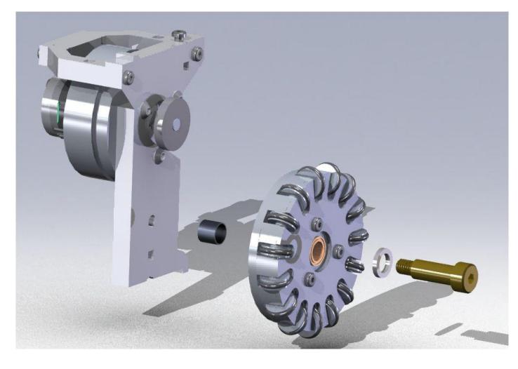
Another problem we resolved this year was the problem of wheels unscrewing themselves while running. We retrofitted small ball-bearings into each wheel so that the screw holding the wheel on the axis does not spin and unseat itself.
We have also had to make small changes in screw placements for better access to the motor modules since our electronics board is larger than we had anticipated.
5.2 Increase in Design Modularity
Our team has further increased the modularity of our robots; in past years, disassembling certain modules would entail disassembly of the entire robot, making maintenance a tiresome and timeconsuming affair. The robot is now much more modular, with a well-defined chassis, and modules can now be removed by removing no more than two easily accessible screws. This should decrease turnaround time between sub-teams when repair requests are made, or possibly allow non-mechanical sub-teams to make quick fixes.
The kicker module has been redesigned so that it may be removed from the bottom plate only; in previous iterations the screws holding the kicker in place had to be accessed from underneath the bottom plate and from above the top plate; however the screws in the top plate were underneath the motherboard, and so dismounting the kicker would necessitate disconnecting components and removing the motherboard. In the new design the kicker is mounted only to the bottom plate, requiring access to only two screws in the bottom plate.
The shield module is no longer dependent on the motor mounts; in previous iterations the motor mounts were partially constrained by a pylon extending from the body of the motor mount which matched a rectangular slot in the top plate. The shields would then be mounted to the top of these pylons. Removing the motor mounts for maintenance, however, would necessitate removing the top plates, since the pylons prevented the motor mounts from simply sliding out. In the new design, the shield mounting points are independent of the motor mounts, now being mounted on purchased standoffs. The new motor mounts can now be removed without having to remove the top plate (and thus the motherboard), making motor mount repairs and maintenance significantly easier.
5.3 Greater use of standard parts
Over the past few years the team has recognized that designing robots with custom-made parts causes major problems further down the design timeline; parts are time consuming to make, and if tolerances are not held, will cause inconsistent robot performance. Buying standard parts ensures that the part tolerances are well known, and the design takes much less time to build, so new iterations can be quickly made.
In particular this year our team has introduced precision-ground brass shoulder bolts for mounting wheel modules to the chassis. Previously, the mounting shaft was a manually made part with four machining operations and was the source of many mechanical problems – wheel precession, gears unmeshing, and inconsistent friction. The ability to rapidly iterate through designs and to have consistent performance between robots is well worth the increased cost of parts.
6 Acknowledgments
We could not have made it this far without the support of our sponsors: School of Engineering and Applied Sciences at Harvard University and the Edgerton Center at the Massachusetts Institute of Technology. We would also like to give special thanks to Radhika Nagpal and Dr. Marie Dahleh of Harvard University and Stephen Banzeart of the Edgerton Center at MIT. We reserve our most heartfelt thanks for Effram, our first robot of the former equivalence class.