RoboFEI 2010 Team Description Paper
José Angelo Gurzoni Jr., Eduardo Nascimento, Daniel Malheiro, Felipe Zanatto, Gabriel Francischini, Luiz Roberto A. Pereira, Milton Cortez, Bruno Tebet, Samuel Martinez, Reinaldo A. C. Bianchi, Flavio Tonidandel
Department of Computer Science, Centro Universitário da FEI; Department of Electrical Engineering, Centro Universitário da FEI; Department of Mechanical Engineering, Centro Universitário da FEI; Centro Universitário da FEI, São Bernardo do Campo, Brazil
Abstract This paper presents an overview of RoboFEI team, who will participate in the Small Size League of the RoboCup 2010, to be held in Singapore. The paper contains descriptions of the mechanical, electrical and software modules, designed to enable the robots to achieve playing soccer capabilities in the dynamic environment of the RoboCup Small Size League.
1 Introduction
RoboFEI team debuted in RoboCup 2009 with a reasonably good performance, passing the the round-robin phase of the competition. Although the results were reasonable, based on the experience gathered during this participation in RoboCup and in other competitions inside Brazil, RoboFEI team presents a new hardware for the 2010 competition, with significant design changes both in the mechanics and electronics of the robots. Due to this significant changes, the paper poses, besides the description of the new hardware, comparisons between the old and new robot models.
The paper also describes the software modules which compose the strategy system of the team, including state predictors and a dynamic role selection method based on market economy.
2 Electronic Design
2.1 Main Board
The new robot electronics consists of two boards. The main board contains all the electronics required to operate the robot, except the power electronics circuit used by the kicking devices. It features a Xilinx Spartan 3 FPGA (X3CS400), used as CPU, through its Microblaze 7.1 IP core, as brushless motor controller and responsible for communicating with the radio and kicker board. Integration of all these functions in the same IC has eliminated difficulties related to the communication and synchronization of different micro controllers, while at same time reducing considerably the number of components on the board. This is an advance in relation to the previous design, which had an ARM7 as main CPU and dedicated 8-bit micro controllers for each motor, allowing faster reading of the odometry sensors and simplified firmware programming. The Xilinx Spartan 3, with its IP core operating at 96 MHz, also provides significantly faster computation, when compared to the 48 MHz of the previous robot, besides to provide future expansion capabilities, due to its high number of available pins.
The radio used on the board is a TRW-24G transceiver (based on the Nordic nRF2401A IC) operating at 2.4 GHz, set at 250 Kbps data rate. The board also has five brushless motor drivers designed with the NDM3000, an SMD mounting IC that features three N-P complementary channels MOSFETs, AD7918 Analogto-Digital circuits for motor current sensing, JTAG and external matrix display (for diagnostics) connectors.
The power to the main board and motors is provided by a 6-cell (22.2V), 2500 mAh, LiPo battery.
2.2 Kicker Board
The kicker board is responsible for controlling both the shooting and the chip kick devices. It has a boost circuit designed with the MC34063 IC, which uses a 100KHz PWM signal to charge a 3300 µF capacitor up to 200V. This IC controls the whole circuit, sparing the main-board's CPU from the need to generate the PWM signal and monitor the capacitor's charge. In relation to the previous design, it represents an increasing of 80% in the capacitor's tension and a 5 times faster charging rate, due to the PWM's higher frequency.
The kicker board features an independent power supply, fed by a 2-cell (7.4V) LiPo battery with 1300 mAh charge. The connections between the kicker and main boards are opto-coupled, to avoid spikes and eventual damage to sensitive electronic circuitry.
3 Mechanical Design
In compliance with the SSL rules, the height of the robot is 148 mm, the maximum percentage of ball coverage is 15% and the maximum projection of the robot on the ground is 146 mm.
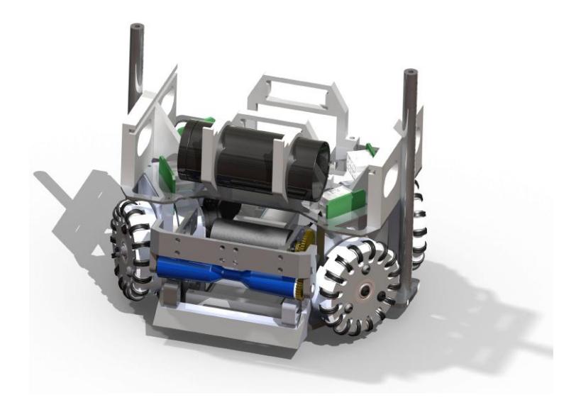
The mechanical design for 2010 presents a significant evolution, in relation to the previous robot. The key changes are the chip-kick implementation, which the previous model lacked, the improvement of the damper system for better ball reception and handling, and a more practical and robust robot frame, taking into consideration the ease of assembly and disassembly.
On the previous robot, replacement of circuit boards and batteries was difficult, requiring a good number of screws to be removed. To solve this problem, sliding rail stands were added, as the support for the electronic boards. The batteries are also slided into its positions, within plastic supports easily accessible from the back of the robot. A general view of the robot can be seen in figure 1.
3.1 Driving System
During RoboCup 2009, it became explicit that, to effectively play an SSL game, a team has to match the demanding parameters of speed and acceleration employed by the other competing teams. It is a must on a game based on quick reactions, and the previous robot, using Faulhaber 2232 DC motors, was not up to that task. Also, the new design was planned not only to match, but to exceed the current status of the competitors. To accomplish this goal, the motors selected are the Maxon EC-45 50W motor, a motor capable of outperforming the motor becoming the de facto standard of the League, the Maxon EC-45 30W. With 6700 RPM no load speed and 822 mNm stall torque, the EC-45 50W allows the RoboFEI 2010 robot to use 3:1 reduction ratio and yet be capable of accelerating above 6 m/s$^2$.
The higher power the motor also allow the robot to be symmetric, with all four wheels disposed at 33° in relation to the longitudinal axis, without making it slower than the faster robots currently on the League.
However, there is a trade-off to be balanced. Adopting the 50W version of the EC45 motor, instead of the 30W, results in around 350 grams weight increase, mainly because the additional 20W power requires a larger battery. This tradeoff is acceptable, though, as the robot gains more than 3 times the maximum stall torque and 1.5 times the maximum speed.
3.2 Wheels
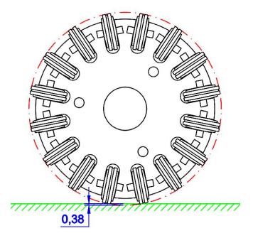
The new wheel design focused on solving the excessive vibrations the previous design had, caused both by the backlash between the small wheel and its mountings, by the small wheels disposition. To achieve this goal, some design changes were applied. The distance from the small wheel to the center of the main wheel was reduced and the small wheels and its axis are now machined as a single piece. This allowed a reduction on the amplitude of the vibration caused by the wheels on the robot, from 2.0 to 0.38 mm. Figure 2 shows the new wheel drawing. With less vibration, the control of the robot becomes smoother and the stress on the mechanical and electronic parts is reduced.
Aside from these benefits, the wheel also became easier to mount and dismount. The rubber rings of the small wheels were also changed, from the O-rings, that used to loosen during the game, to H-rings, which thinner profile, less prune to loosening.
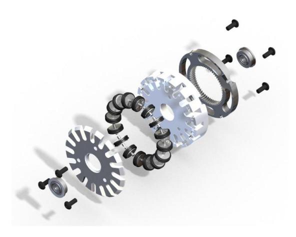
The new wheels can be seen in exploded view on figure 3. They have 58 mm diameter, body made of aluminum and 16 small wheels made of stainless steel. They have two bearings, not one like the previous model, to better handle axial loads.
3.3 Kick System
The Kick device is composed of a 30 mm diameter cylindrical solenoid, built of a 14 mm diameter SAE1020 steel core, where 4 AWG21 wires are coiled, in parallel. A major improvement on the new kick device is the increase in the distance traveled by the plunger, to 36 mm. The longer the distance, the more acceleration the plunger achieves, resulting in stronger kicking force.
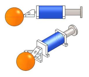
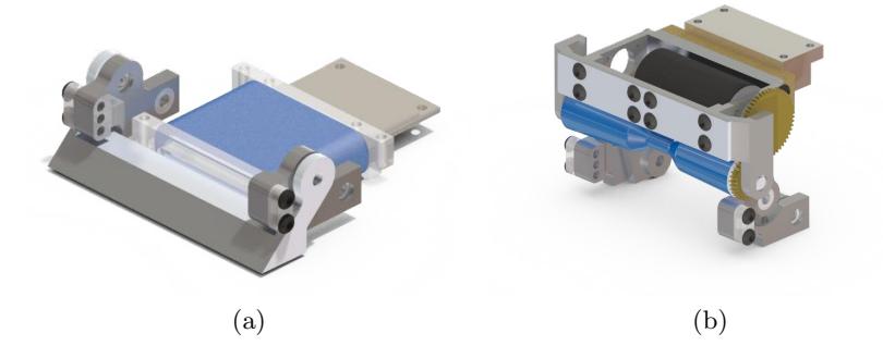
To position the kick device at the center of the ball, the aluminum part attached to the plunger that touches the ball had to be offset, in relation to the axis of the solenoid, as shown in figure 4.
The chip-kick device consists of a rectangular solenoid mounted under the cylindrical solenoid of the kick device. Its core is made of nylon, to reduce weight, where a 3.75 mm width steel plunger rests. When activated, the plunger pushes the aluminum part, launching the ball with a 45° angle. It can be seen in figure 5(a).
3.4 Roller and Damper Systems
On the 2010 robot, the Maxon EC22 20W motor replaces the Faulhaber 2224 as the motor on the roller device. Not only the EC22 is more powerful than the 2224, it achieves 5 times more no-load speed, 35500 RPM, allowing the roller device to have greater angular speed while maintaining the required torque.
For improved efficiency, the rolling rod itself, made of rubber, has its ball contact width increased to 82 mm, and its outer diameter dwindles 2 ° toward the center of the rod. As the rod rolls, this dwindling causes the ball to move toward its center.
The damping system is mounted on the back of the roller device, as figure 5(b) shows. The damping is responsible for improving the ball control during pass receptions and helps the ball control when it is on the roller and the robot moves. The articulated parts of the device use bearings, to improve efficiency.
4 Motion Control
RoboFEI 2010's motion control, as in its predecessor, is completely embedded into the on-board CPU. The strategy module sends, via radio, the distance and direction of translation, the amount of rotation and the speed desired. The translation vector is given in polar coordinates, where ρ is the direction of the movement, relative to the robot's front, and r is the distance to be traveled. The rotation θ represents the angle the robot must turn on its center, also in relation to the robot's front, and the speed is given as percentage of the robot's maximum speed. With the information received from the strategy, the onboard CPU decomposes the vectors, using the omnidirectional velocity and force coupling matrices [1], and the PI translational and rotational motion controller loops execute. The feedback for the control loops is calculated with the odometry of the wheels and the pseudo-inverse matrices. This odometry data collection is performed at 1KHz, while the PI control loops have 250Hz cycle. The odometry resolution is 4320 pulses/revolution.
The main advantage of the on-board processing is the ability to directly use odometry data in the omnidirectional matrices, thus being able to correct the robot translation and rotation movement faster than if vision feedback was to be used alone. Individual PI controllers for each wheel are also used, at 1KHz cycle, to maintain the desired wheel speeds.
5 Path Planning and Obstacle avoidance
The path planning and obstacle avoidance algorithm employed is based on the Rapid-Exploring Random Tree (RRT) with KD-Tree data structures, proposed by [2], and on the ERRT algorithm developed by [3], complemented by an algorithm to include preferred path heuristics and set the angle of approach. The algorithm based on RRT was chosen because (i) its capacity to efficiently explore large state spaces using randomization, (ii) the probabilistic completeness offered, (iii) its lookahead feature and (iv) the easiness of the algorithm's extension, when new constraints or heuristics are deemed necessary.
This section focuses on describing this add-on algorithm, which is implemented on top of the ERRT base algorithm.
The add-on algorithm has the function to set the angle which the robot approaches the ending point, as commanded by the strategy layer, an item that many path planners do not treat. It is not desirable, for example, that a robot going to the ball on the defensive field accidentally hits the ball in the direction of its own goal, or yet, that an attacking robot arrives at the ball in a position in between the ball and the opponent's goal. To create a path that conforms to the angle of approach requirement, a circular virtual obstacle centered on the ending point is created, with a 10° width circle segment and vertex at the desired angle removed. This effectively forces the path planner to create a path the reaches the ending point passing through this 10° opening. The radius of this obstacle-like constraint is set to a value close to half the size of a robot.
6 Software System
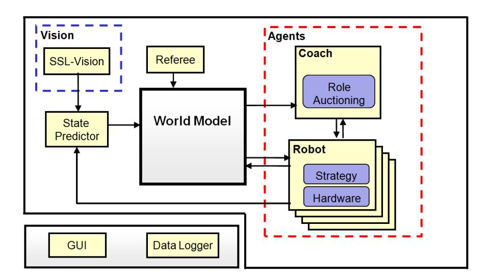
RoboFEI software system consists basically of some world modeling blocks, logically independent agent modules, and visualization and data logging blocks. Figure 6 shows the diagram of the architecture.
6.1 World Modeling via State Predictor
The world model is updated by the state predictor module. This module receives vision data from the SSL-Vision and motion command data from the agent modules, sent when they command the robots via radio, and performs state predictions, The prediction is to advance the positions sent by the SSL-Vision from their original capture time to the present and then forwarding one strategy cycle in the future, the so called latency of the strategy system. This latency is currently on the order of 80ms.
The prediction algorithms used for ball, robots and adversaries are different. The ball prediction is made by an Extended Kalman filter (EKF) (see [4]), a well known method for position estimation.
The robot's prediction is performed similarly to [5], with multi-layer perceptron neural networks. These networks are trained off-line to learn the robot's motion model, receiving past frames and motion commands as input and a frame n steps in the future as output. Once trained, the networks are used for on-line estimation of the robot's position and rotation.
As for opponent estimation, currently it is done with simple extrapolation of the last velocity data and Gaussian functions.
6.2 Agent Modules
Each robot player is an independent module, executing its own instance of one or more strategy submodules and its hardware specific functions (such as motion control and sensing). The current implementation relies basically on a layered strategy architecture and a market based approach for dynamic allocation of functions, both described ahead on this section.
6.3 Strategy module
Building multi-agent systems in a layered architecture with different levels of abstraction is a popular approach (see [6], [7] and [8]) well suited as foundation for machine learning algorithms, one of the research goals. For this reason, the strategy module architecture was divided in three abstraction layers.
The lowest layer has the so called Primitives. Primitives are actions that mostly involve directly activating or deactivating a hardware module such as to kick the ball with a given strength, activate the dribbling device, rotate or move to a position. Actually, moving to a position is a special case of a primitive with underlying complex logic. It calls the path planning system to perform obstacle avoidance.
On top of the primitive layer, is the Skills layer. Skills are also short duration actions but involving use of one or more primitives and additional computation, such as angle calculations, speed estimation or forecasting of objects' positions, measurement of a primitive task's completion and verification of obstacles displacement. This layer has a small set of skill functions, yet that represent the basic skills required in a robot soccer game, like shooting the ball to the goal (aiming where to shoot), passing the ball to a teammate, dribbling, defending the goal line or tackling the ball (moving toward the ball and kicking it away).
These skills are employed by the Roles layer, that contains different roles created using combinations of skills and the logic required to coordinate their execution. There are roles called fullback, defender, midfielder, striker, forward and attacker. No particular robot is tied to a given role (except the goalkeeper), and there is no limitation on the number of instances of the same role can exist, what allow dynamic selection mechanisms to operate freely on combination of roles.
6.4 Market-Based Dynamic Role Selection
Dynamic role selection is key to the strategy, as it allows the team to have, for example, three defenders when in a defensive situation and three attackers and a mid-fielder when attacking, as well as to adapt to different opponent behaviors.
On RoboFEI 2010, a market-based approach for role allocation is under experimentation. The algorithm is designed in a similar fashion to the Murdoch [9], with the tasks being the player roles. The available roles are auctioned by the coach and the players bid for them. These bids represent the utility, or fitness, of the player to perform the role, as calculated by the player itself, and are key for the auctions to work properly, as improper values would mislead the selection.
The utility functions represent how well a player can perform that role, given the teammates, opponents and ball positions on present and few past frames. The functions consist of evaluation metrics for a particular role, producing a scalar as result of the weighted sum of each metric. The weights are predefined, in the lab.
An auction works as follows:
- The start of the auction is announced by the coach, along with the list of roles;
- The player's utility function calculates a scalar value for each of the roles being auctioned and submits back to the coach;
- The coach, using the Hungarian method [10], selects the best combination of winners, maximizing the scalars received;
- The coach announces the winner players, who start to perform the given roles.
The auctioning cycle occurs every ten seconds.
Acknowledgments
We would like to thank, in advance, the Small Size League Committee, for the consideration of our material. We would like also to immensely thank the staff of Centro Universitário da FEI, for all the help we always received.
References
- Rojas, R., Förster, A.G.: Holonomic control of a robot with an omnidirectional drive. KI - Künstliche Intelligenz 20(2) (2006) 12–17
- Atramentov, A., LaValle, S.M.: Efficient nearest neighbor searching for motion planning. In: IEEE International Conference on Robotics and Automation. (2002) 632–637
- Bruce, J., Veloso, M.: Real-time randomized path planning for robot navigation. In: Proceedings of IROS-2002. (2002)
- Welch, G., Bishop, G.: An introduction to the kalman filter. Technical Report TR 95-041, Department of Computer Science, University of North Carolina (2001)
- Behnke, S., Egorova, A., Gloye, A., Rojas, R., Simon, M.: Predicting away robot control latency. In: Proceedings of 7th RoboCup International Symposium. Springer (2003)
- Mataric, M.J.: Learning in behavior-based multi-robot systems: Policies, models, and other agents. Cognitive Systems Research (April 2001) 81–93
- Bowling, M., Browning, B., Veloso, M.: Plays as effective multiagent plans enabling opponent-adaptive play selection. In: Proceedings of International Conference on Automated Planning and Scheduling (ICAPS'04). (2004)
- Browning, B., Bruce, J., Bowling, M., Veloso, M.: Stp: Skills, tactics and plays for multi-robot control in adversarial environments. In: IEEE Journal of Control and Systems Engineering. Volume 219. (2005) 33–52
- Gerkey, B., Matarić, M.: Sold!: auction methods for multirobot coordination. Robotics and Automation, IEEE Transactions on 18(5) (2002) 758–768
- Kuhn, H.W.: The hungarian method for the assignment problem. Naval Research Logistics Quarterly 2(1) (1955) 83–97