RoboPET Team Description Paper
Acauhã dos Santos Fialho, Arthur Crippa Búrigo, Bruno Jurkovski, Cássio Klen de Azevedo, Cristian Adolfo, Cristiano Medeiros Dalbem, Eduardo de Melo Leonardi, Fábio da Fontoura Beltrão, Felipe Augusto Chies, Gabriel Hubert Silva, Igor Antônio Schmidt, Ingrid Flesch Lopes, João Phellip de Mello Bones da Rocha, Kauê Soares da Silveira, Luca Couto Manique Barreto, Lucas Fialho Zawacki, Marcos Vinicius Cavinato, Dante Augusto Couto Barone
Instituto de Informática, Universidade Federal do Rio Grande do Sul (UFRGS), 9500 Bento Gonçalves Avenue, Agronomia, Porto Alegre, Brazil
http://www.inf.ufrgs.br/pet/robopet
Abstract This paper presents an overview about RoboPET 2010 project, a Robocup Small Size League team of Brazillian graduation students of Computer Science, Computer Engineering, Mechanical Engineering and Electrical Engineering. This paper will outline the most important details of both the robot hardware and software architecture.
1 Introduction
RoboPET is a team of Small Size F180 robot soccer developed at the Universidade Federal do Rio Grande do Sul. The team has participated in Robocup 2009 and has, besides some problems, obtained some good results. In the second semester of 2009 the team has gone through a big refactoring, specially at the decision system and mechanical structure of the robot. By the time of the writing of this paper the new physical robots aren't ready, but the project described here is the architecture we've designed and is being worked on now.
2.1 Architecture
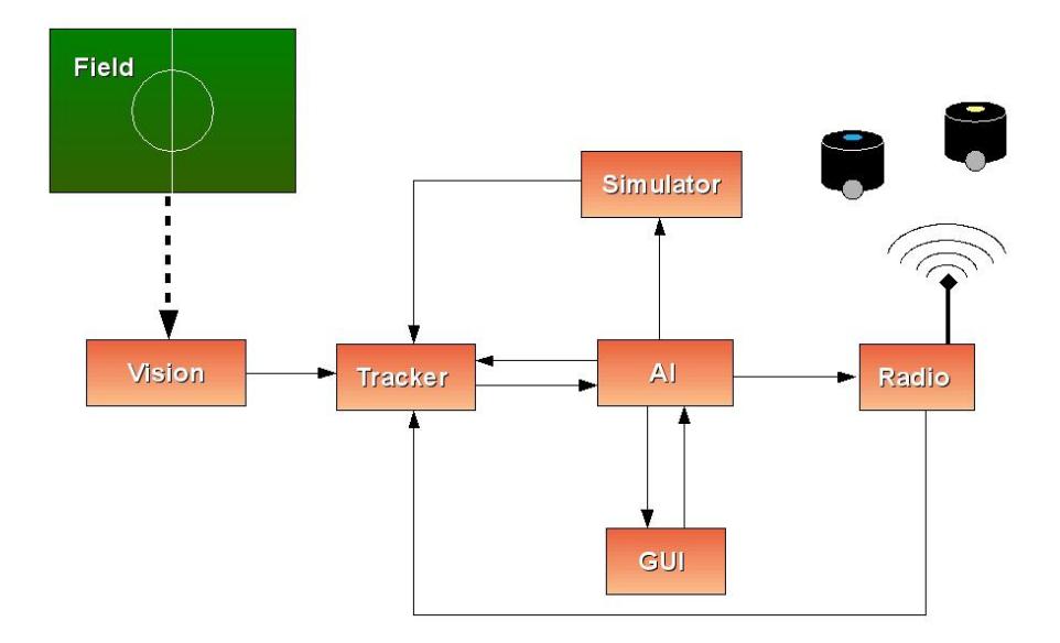
We developed a modular architecture (as seen in Fig. 1), in which each module is a separate executable file. The communication is done through UDP sockets, and the serialization/deserialization uses Google Protocol Buffers [1]. This facilitates the development and integration, allowing the replacement of only some of the modules, e.g. for earlier versions, without having to recompile or re-run the whole system.
Vision The SSL Vision. When we are in a real game (as opposed to a simulated game), it receives the images from the field and sends the data (positions and ids of the robots and the ball) to the Tracker.
Tracker The Extended Kalman Filter. It receives data from the AI (actions sent to the robots) and SSL (positions of players and ball) and Radio (battery charge and speed of the robot measured by the encoders) or Simulator (depending on whether we are in a simulated game or in a real game). Then it sends the corrected data (positions, velocities, accelerations and angles of the robots and the ball) for the AI.
Simulator Receives the actions of the AI, simulating the results and sends them to the Tracker.
GUI Gets debugging information about the internal state of AI, and their actions, and sends settings (setting a state, control of robots, etc.) to AI.
Radio When we are in a real game, receives the actions of AI and sends them to the robots, sending feedback from the robots (speed and battery charging) to the Tracker.
The tests with real robots are held monthly, with only the most mature part of the system, allowing a comparison of reality with simulations and a better adaptation to it, besides getting an overview of the team.
3.1 Vision
Due to changes in the rules for the category this year, all teams must use SSL Vision [2]. We are adapting ourselves to it and we intend to soon start to contribute with its code.
Currently we are developing (in C++) the Extended Kalman Filter [3] to perform the tracking of the robots and the ball with more accuracy.
3.2 Artificial Intelligence
The Lua programming language [4] is used for the specification of agents, together with C++. Lua, being interpreted, allows us to change these specifications without having to recompile or re-run any program. Another advantage is that there is less bureaucracy to create the code than C++, which facilitates maintenance and early contributions by new members of the group.
AI is a hierarchy of state machines, where higher level state machines leads to lower level ones, and so on until reaching the lowest level, which determine an atomic action for each agent. This approach demonstrates to be very advantageous because it allows high reuse of code and a greater clarity.
3.3 Simulation
For testing purposes, a simulator is being developed. So, very soon we will be testing in a realistic simulation environment, which can provide feedback close to real robots. The use of a simulator is justified not to risk the integrity of robots with code that has just been written, and avoids the overhead of integration with other areas, field installation and maintenance of robots required for the physical tests.
This simulator is developed in C++.
3.4 Techniques
We will be using the method of potential fields [5] to evaluate the positions and actions of the robots, and Rapidly Exploring Random Trees (RRT) [6] and Dynamic Safety Search (DSS) [6], which are already consolidated in the literature, for robots path planning.
3.5 Graphical User Interface
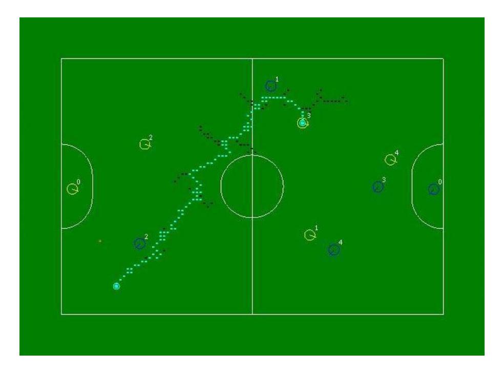
We are also developing a GUI (Graphical User Interface) that allows to view the current state of AI in the game and the decisions taken, thus facilitating testing and error detection. It will also generate a log file of the game (real or simulated), which can then be replayed, enabling the improvement of the team and the identification of mistakes made and passed unnoticed. Furthermore, it allows you to modify the behavior of the team, for example by setting a fixed state, to facilitate testing of new or recently modified parts. It is developed using C++, together with the GTK graphics library [7].
4.1 Eletronics
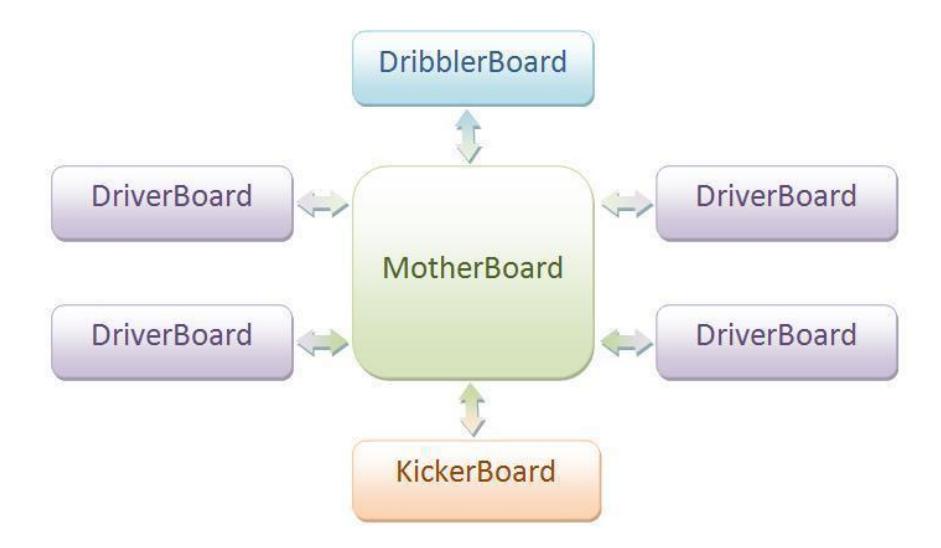
Due to the new motor - a DC-brushless - and the desire of having a faster and more efficient hardware able to control the motor velocity and provide a feedback, all the electronics of the robot has been redesigned. With the goal of creating a modular eletronics to facilitate possible repairs (in the case of a hardware failure), the hardware was divided in four parts: KickerBoard, DribblerBoard, DriverBoard and MotherBoard.
KickerBoard The KickerBoard is responsible for the robot kick, i.e., it communicates - serially - with the MotherBoard, receiving the kick data and, thereby, activates the solenoids correctly. To activate the solenoids and to make the ball reach a speed of 10m/s, it's necessary to elevate the 18,5V tension provided by the battery to 250V - using, for this, two capacitors of 2700uF in parallel and a DC-DC converter (Boost).
DriverBoard The DriverBoard is responsible to control the motor spin. The four DriverBoards - one for each wheel motor - are connected to the MotherBoard and they receive the speed each motor must develop. In addition to generate the PWM signals to the brushless motors - using the IC MC33035 -, this board also receives the signal of each one of the encoder motor to provide a feedback of the velocity developed. The encoder was built in laboratory with a simple system utilizing infrared emitters and infrared receptors that generates 1024 pulses per wheel rotation.
DribblerBoard Similar to the DriverBoard, the DribblerBoard controls the robot's dribbling system. The infrared sensors - placed in the robot chassis to identify the ball's presence in front of the mechanical dribbling system - are connected to this board. When the ball is just in front of the robot, the board activates the dribbler motor. None encoder system was coupled in this board, because it's thought that there is no need of that much precision for the dribbling system. Besides, this board communicates with the MotherBoard, signalizing the ball's presence.
MotherBoard The MotherBoard is responsible for the communication - through radio - of the robots with the main server. The radio was changed to the transceiver TRW-24G of 2.4GHz of frequency, that helped to ease the problems of interference faced with the old module. This board receives the displacement, the dribble and the kick vectors and returns the real speed, the ball's presence in front of the robot and the charge level of the batteries.
It's through this board that all the commitments of the robot are organized. It has an interface that allows the adjustment and the visualization of the robot status and it's also able to turn on, to turn off and to restart the system. The communication with the other boards is done using both by parallel communication and serial communication, depending on the quantity of information to be transmitted.
Batteries The energy provided to the motors and to the kick system comes from a 18,5V LiPo battery. Besides, the robot has a 7,4V LiPo battery to feed each one of the boards.
5 Mechanical Design
Due to the low yield of the first generation of robots and after our experience in RoboCup 2009, our team took as one of its main focuses the mechanical development. Starting a new project, we tried to create a new generation of robots that would meet all the needs of a robot for the category F-180 efficiently.
5.1 Driver System
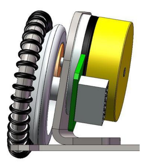
In the spirit of ensuring a good response to the omni-directional movement, it replaces the old DC motors for Maxon EC 45 flat-50W brushless motors. It also increased the number of three wheels to four. The system that consists of motor, encoder and wheel has been modularized to facilitate exchange of components and fitting in the main chassis. Among the main features of the driver system can be observed the following:
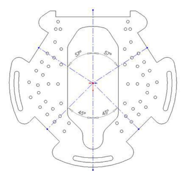
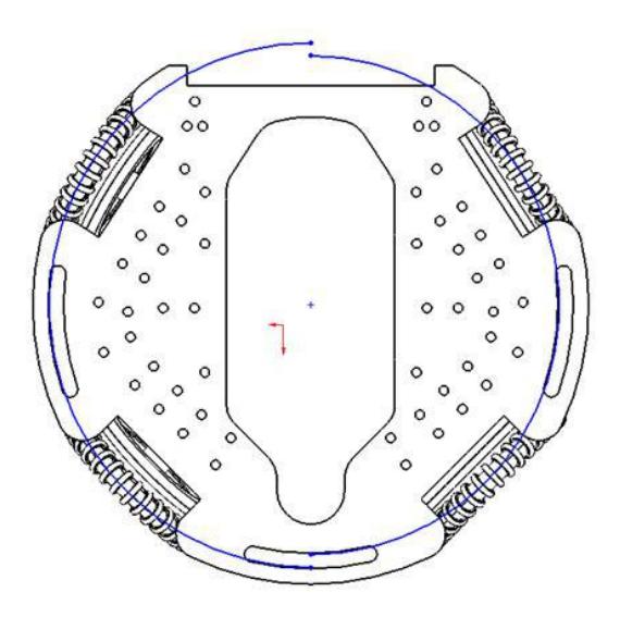
Angles between the wheels Making a trade-off between the pursuit of space to the kick system inside the robot and symmetry of the wheels to facilitate the movement omni-directional in its three degrees of freedom - translating in x and y and rotating in z - the wheels was separated as shown in Fig. 4. It was observed that changing the space for the solenoid system was also effective because it increased the power of the robot motion in directions that our artificial intelligence tends to ask more often.
5.2 Dribbling System
To increase the rotation speed of the dribbler system the motor used previously was replaced by the Maxon EC16 BL 15W motor. The diameter of the rotating cylinder was reduced to increase the possible degrees of kick up. Moreover, all dribbling system is also modularized.
5.3 Kicking System
Seeking to expand the range of possibilities to kick through a combination of vectors in y and z, it was developed a mechanical system capable to operate both solenoids at the same time. Thus, we can combine forces in y - coming from the main solenoid and flat - and z - coming only from the flat - defined by the intelligence and executed by the electronics of the kick to improve possible trajectories for the ball.
5.4 Robot's Structure
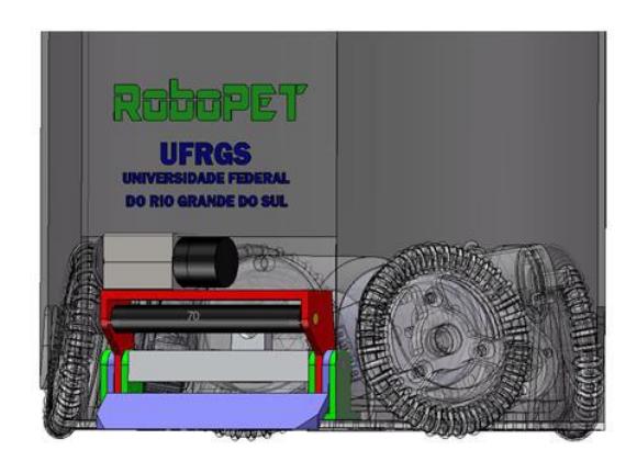
The material used for the main structure of the robot is still aluminum because of strength, weight and cost. The most significant change in the material used was the outer covering of the robot, as mentioned above, which uses polyethylene terephthalate - the common recycled plastic used in drinks bottles. It is a polymeric material with one of the greatest resistance to impact of the market. Due to the inclination of the wheels of the project, will be possible to partially cover the top of the wheels, providing greater safety and crashworthiness. Table 1 shows the general specifications of the robot.
Table 1. General specifications of the robot
| Height | 140 mm |
|---|---|
| Maximum diameter | 180 mm |
| Maximum Pool Coverage | 19.6% |
| Weight | 4750 g |
| Displacement of Center of Mass (For the (0,0,0) in mm) | (0.14, -0.68,19.15) |
| Material Chassis | Steel / Aluminum |
| Material of gears / pulleys | Steel / Polyamide 6.6 |
| Material of External Coating | Polyethylene terephthalate |
6 Conclusion
This paper gave an overview of RoboPET 2010 Team, which, besides not finished yet, is already under development. The new physical robots as described here shall be complete by March or April 2010. Since our main problems on last year's Robocup were our robot motors and radio, we hope we'll do a better participation on next national and international competitions once the new robots are done.
References
- Google Protocol Buffers, http://code.google.com/apis/protocolbuffers/
- Zickler, S., Laue, T., Birbach, O., Wongphati, M., Veloso, M.: SSL-Vision: The Shared Vision System for the RoboCup Small Size League. In: Proceedings of the RoboCup Symposium 2009 (2009)
- Cuevas, E., Zaldivarl, D., Rojasl, R.: Kalman filter for vision tracking
- Ierusalimschy, R., de Figueiredo, L. H., Celes, W.: Lua an extensible extension language. Software: Practice & Experience 26 #6 (1996) 635–652.
- Koren, Y., Borenstein, J.: Potential field methods and their inherent limitations for mobile robot navigation. In: Proceedings of the IEEE International Conference on Robotics and Automation. (April 1991) 1398–1404
- Bruce, J.R.: Real-Time Motion Planning and Safe Navigation in Dynamic Multi-Robot Environments. PhD thesis, Carnegie Mellon University (Dec 2006)
- The GTK+ Project, http://www.gtk.org/