2010 Team Description Paper: UBC Thunderbots
Alim Jiwa, Byron Knoll, Christopher Head, Howard Hu, Jonathan Fraser, Jonathan Serion, Kevin Baillie, Lok Tin Lam
The University of British Columbia 2329 West Mall, Vancouver, BC Canada V6T 1Z4
Abstract This paper details the 2010 design of UBC's Small Size League team, to be entered at Robocup 2010 in Singapore. The focus this year was mainly on addressing the mechanical and electrical weaknesses in the robot from last year, and building on the existing artificial intelligence to implement new behaviours and features.
1 Mechanical Design
The maximum dimensions for this year's robot can be found below in Table 1.
Table 1: Maximum Robot Dimensions
| Dimension | Value |
|---|---|
| Maximum Height | 148 mm |
| Maximum Diameter | 178 mm |
| Maximum Ball Coverage | 19% |
1.1 Drivetrain
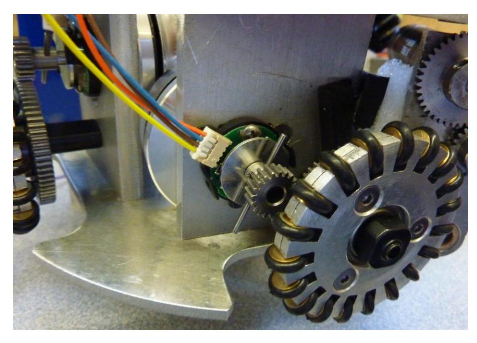
The robots designed this year consist of 4 omni-directional wheels. The two front wheels are separated with an angle of 114 degrees while the back wheels are 90 degrees apart. This configuration is based on a simulation model which allows the robot to move faster in the lateral direction while still obtaining sufficient forward velocity.
This year's motors have also changed from four Mabuchi brushed DC motors to 30 watt Maxon brushless motors due to size constraints and higher performance parameters. The drivetrain uses a gear ratio of 2:7 to increase torque from the motor. An external encoder is used to measure the speed of the wheel instead of build in hall sensors, to obtain higher resolution.
The wheels used this year are modified from the set of wheels manufactured by an Iranian company to fit into our mechanical design. They are 45mm in diameter and mostly composed of aluminum. O-rings are used for each of the rollers to obtain better traction between the wheel and the field surface.
1.2 Kicking System
In 2009, our robots' kicking systems did not kick the ball with satisfactory speed, averaging between 1.5 and 2 m/s. The driving solenoids were charged directly by the main 15 volt battery at low current, with a simple kicking mechanism that included much friction.
For the 2010 robots, the kicking system was redesigned, but with the same principle of operation (using solenoids to power the kicker). The new system includes a kicker as well as a fixed angle chipper, which use different solenoids but the same power source. Measures were made to increase the number of ampere turns, reduce the friction of the system, and maximize the stroke length of the solenoid. The kicker and chipper system use off-the-shelf solenoids with plans to develop custom wound solenoids to save space. The kicking system is able to kick at a speed of 8 m/s currently with further improvements being made, and the chipping system is still undergoing testing.
Both systems are driven using capacitors that are charged to high voltages (250 V) using a boost converter circuit. Using this boost converter circuit, the capacitors are able to quickly charge so that rapid kicking can be achieved. The boost converter system operates as a stand alone system whose function is controlled by the main logic circuit board, but is optically isolated to provide protection from the high voltages. The solenoids are connected to the capacitors through power mosfets so that variable speed kicking can be achieved through pulse width modulation. This also allows the distance the ball is chipped to be varied at game time.
1.3 Dribbling System
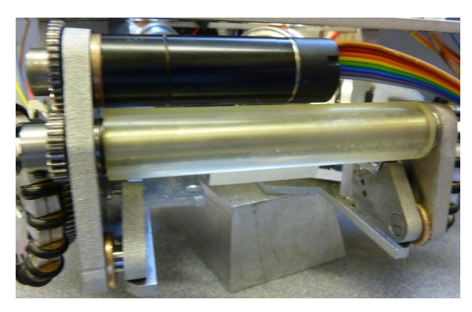
The 2010 dribbler design aims to improve on every facet of its performance over the 2009 design. To do so, our research pointed to the need for a damping mechanism beyond a soft roller material, and also a higher performance motor to improve on backspin and torque. This year's design uses a MAXON EC-16 brushless DC motor to provide a nominal 8000rpm on the roller. Our test has shown that this motor is able to sustain stationary dribbling as well as provide sufficient back spin to achieve reverse passing techniques if desired.
A new polyurethane roller is used to increase the grip of the dribbling system on the ball and also to improve on the damping capabilities. Several durometer hardness parameters were tested for polyurethane and our results support A25 shore polyurethane material to be the most suitable candidate. Furthermore, a hinged dribbler design is being used in conjunction with damping foam to facilitate pass reception. Continual testing on the performance of the dribbler is necessary to further determine the required material to properly dampen the dribbler for pass reception.
In the meantime, the mechanical system is designed with modularity in mind to allow for future tuning.
2 Electronics
2.1 Logic
Our redesign of robots from 2009 to 2010 includes a completely new electrical subsystem, designed from scratch in concert with the mechanical changes. In 2009, a Wiring board (a close relative of the Arduino line of boards) containing an AVR microcontroller was used for all on-board control tasks. In 2010, we have replaced this with a Xilinx XC3S50A FPGA, allowing the task of reading optical encoders on the drive shafts to be brought on-board rather than being performed by auxiliary hardware. Since the XC3S50A does not have any analogue-to-digital converters on board, a Microchip PIC18F4550 is included on the board to take analogue readings and transmit them to the FPGA by SPI. The PIC18F4550 is also attached to the radio communication hardware and the Flash memory that holds the FPGA's configuration, allowing new FPGA bitstreams to be sent wirelessly to the robot even if the bitstream already present on the robot is malfunctioning and cannot communicate wirelessly (uploading a complete bitstream from the host computer to a robot takes around fifteen seconds).
2.2 Motor Control
In 2009, the drive motors were brushed-type DC motors and were driven by prebuilt H-bridge modules plugged into the main circuit board, and the dribbler motor was also a brushed DC motor but, being unidirectional, was powered by a single MOSFET on the main circuit board. In 2010, we have replaced all five motors with brushless DC motors from Maxon Motor. To control these motors, we are using the MC33035 motor controller chip. Five MC33035s and associated phase-driver MOSFETs are collected on a "motor controller board", which receives direction and power information from the main board and sends fault and speed information back to the main board over a ribbon cable.
2.3 Power
In 2009, the robot was powered with two separate batteries, a 15V battery for the motors and a separate 11V battery for the logic, stepped down with a 7805 linear regulator. In 2010, the 11V battery has been removed and all robot hardware is powered by the 15V battery. To resolve thermal issues around stepping 15V down to 5V, the 7805 was replaced with a 78ST105 switching regulator. 3.3V and 1.2V rails needed by the logic are then generated by low-dropout linear regulators.
In 2009, the kicker solenoid was powered directly from the 15V battery through a MOSFET located on a separate circuit board. In 2010, the kicker (and new chipper) solenoids will be powered from a capacitor charged to a high voltage by an LT3751 charger chip, and this circuit will be on the same board as the logic components (FPGA, PIC18F4550, Flash memory, XBee, and so on). Use of the LT3751 was attempted in 2009, but no working circuit was produced.
2.4 Communication
For communication with the host computer, XBee 802.15.4 communication modules from Digi International were used in 2009, and as no problems were encountered around communication, the same modules are being used in 2010. However, in 2010, the baud rate of the serial lines on the XBee modules has been raised from 56kbps to 250kbps (with an unintuitive increase in reliability, since the modules are not actually capable of producing a bit clock of exactly 57600Hz but can create one of 250000Hz); also, some of the auxiliary remotely-controllable digital output lines are being used to communicate with the PIC18F4550 (during normal operation, the PIC18F4550 ignores the serial lines to and from the XBee and allows the FPGA to perform all communication) in order to signal an entry to bootloader mode, where new FPGA bitstreams can be uploaded. Once we have a full fleet's worth of circuit boards assembled, we are planning to re-evaluate our choice of communication protocol for better performance: in 2009, we simply sent each robot a unicast radio packet at a regular frequency containing the relevant fields; for 2010, we are considering instead using a broadcast packet for bulk data transfer and allocating each robot a semi-permanent "slot" in the packet's payload area, thus amortizing the cost of a clear-channel assessment, radio preamble, and 802.15 packet header across the number of robots on the field (unicast packets would still be used for time-insensitive tasks such as bootloading, discovering robots, and allocating slots).
3 Control
The control system for the 2010 class of robots will be substantially similar to our previous year's robots, with some notable exceptions with regards to wheel slip and the overall positional control system. The changes in this year's robot are designed to address deficiencies last year. The most notable two of these, were the inability to accelerate at any real rate without losing control, and the inability to travel in the lateral direction. This system is broken down into two major control loops, the first, which controls the individual wheel speeds and exists on board each robot and, the second, which provide AI level positioning control for each of the robots.
The wheel speeds are each controlled independently receiving set points from the AI off field. Each wheel controller receives speed feedback from optical encoders mounted on the motors, and provides a single control output which is then sent via PWM to the corresponding motor controller. The controller itself will be tuned using Q design and will implement an arbitrary 2nd order system as opposed to a rigid PID controller which is restricted to a single form and may not provide the desired control action. The new wheels in 2010 should allow for more torque before wheel slip occurs thus allowing the controller performance to be tuned higher. This improvement should provide a more idealized response model from the overall robot. Additionally, the computations described in [1] are performed to ensure that the wheel torque never rises above the slip condition, and to ensure that the force vector produced by the four wheels lies within the subspace that will produce robot motion thus minimizing unnecessary current draw.
The AI level of control will differ significantly from 2009. Last year, a simple 2nd order controller was used to perform the overall positional control of the robots. Receiving the absolute position and orientation of each robot from the vision system this was compared to the desired robot position, a set point provided by the strategies portion of the AI, to provide an error signal to a simple linear controller. This year, however, we acknowledge that the velocity profile of the robot is not circular and therefore the control system is nonlinear. As such, a new non-linear controller will be placed into the AI in order to control the final position of the robot. This controller may be based on a fuzzy logic system, or similar scheme developed in parallel, with the decision to be made based on final robot performance under these systems. The set points produced by this controller will be rotated onto the robots coordinate frame, and then transformed into motor set points to be sent out over the wireless communication link.
In conclusion, the overall structure of the system will remain consistent with last year's robots; however, improvements have been made to address last year's weaknesses. Updates to the force vector control should allow for prevent wheel slip thus improving controllability. Likewise up dates to the positional controller should ensure that reasonable set points are always being provided to the robots thus preventing windup and saturation issues in the robot.
4 Software
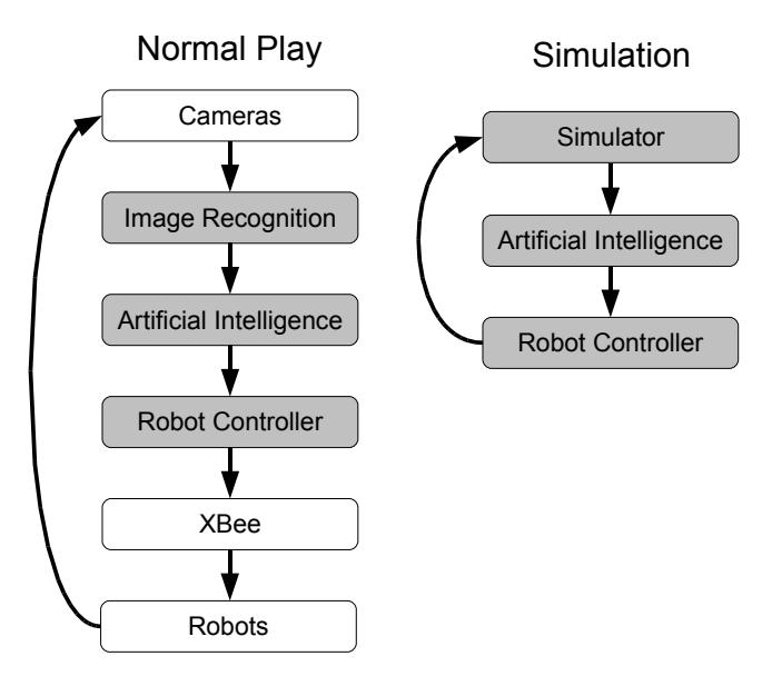
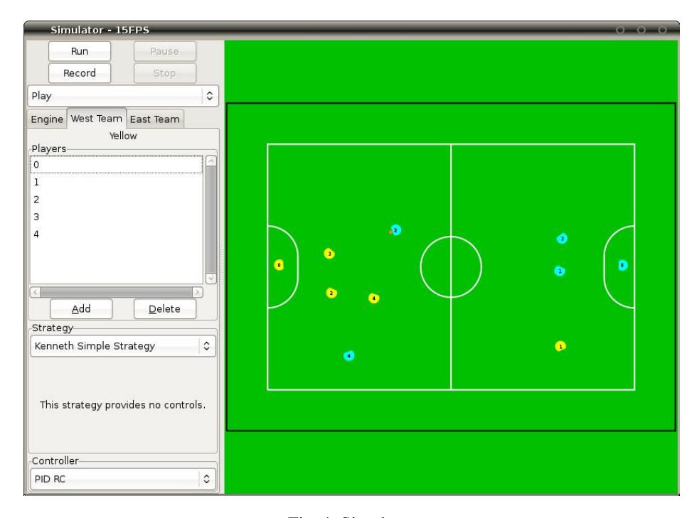
We are using the same high level design for the AI as we used in 2009. However, we decided to reimplement much of the software from scratch in order to improve upon code organization and implementation details. The different software components are visualized in figure 3. The arrows represent the flow of execution and the grey boxes represent software modules. The software can be run in either a simulation mode or a mode for normal play. The image recognition module performs processing on the data output by ssl-vision and updates the positions of the ball and robots accordingly. The artificial intelligence module outputs the desired actions of the robots. These actions include destination positions, orientation, dribbler velocity, and kicker power. The robot controller module converts desired orientation and position into desired velocities. In addition to the components in figure 3, our software contains additional features such as a 2D visualizer to examine the current state of the game and a graphical user interface to control various configuration options (figure 4).
We used a simulator to allow development on the AI to occur without requiring the use of physical robots. The simulator receives input from the robot controller and directly updates the positions of the ball and robots on the field. The simulator uses the open source ODE physics engine. The simulator can be run in either real-time or fast mode. The real-time mode is useful for watching behaviours while the fast mode is useful for quickly recording statistics of various benchmarks or game performance. For example, the fast mode can be useful for quickly testing whether a change in the AI resulted in an increase in the scoring performance (when matched up against a different strategy). In addition, we have added functionality to allow refbox signals to be generated automatically so that a game can be simulated without human interaction.
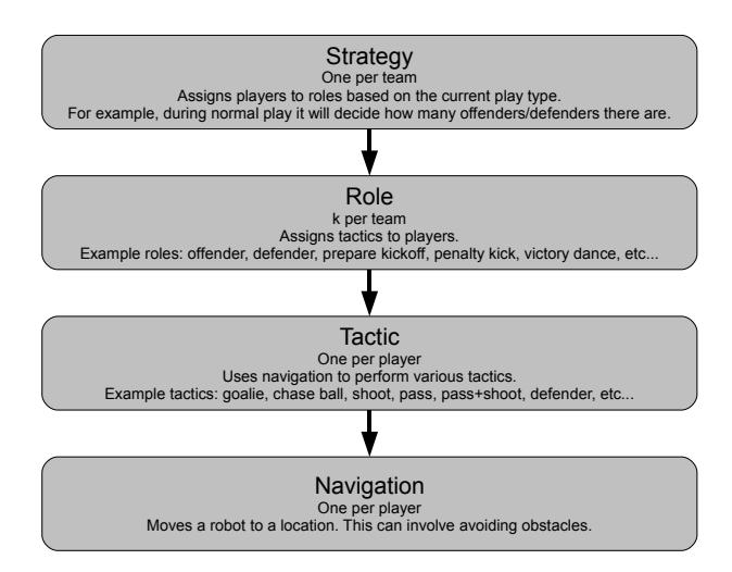
The design of the AI is based on hierarchical control. Designing the AI with a hierarchy of different levels of abstraction offers many advantages over other methods of implementation. Each level of the hierarchy can be designed to focus on accomplishing a particular role with the assumption that the other layers that it interacts with accomplish their roles as well. For example, the layer in charge of controlling the global team strategy can assign lower level behaviours to robots without knowledge of how the behaviours are actually implemented. This hierarchy offers a clear advantage over other task oriented approaches by modularizing the different levels of abstraction. Implementing these independent modules is much simpler than tackling an entire task at once because each module represents a small part of the global problem. Another advantage of using a hierarchy is that from a software engineering perspective it makes the system more extensible and easier to understand. For example, instead of having to completely rewrite the code in order to create a new strategy, only a single layer at the top of the hierarchy would need to be modified. The different layers of the AI are visualized in figure 5. The arrows represent the flow of execution. The top layers perform higher level team organization while the bottom layers perform lower level behaviours specific to a player.
5 Acknowledgements
We'd like to thank the Faculty of Applied Science, departments of Mechanical Engineering; Electrical Engineering; Engineering Physics; and Computer Science, in addition to the University of British Columbia for their support. We'd also like to thank all our sponsors for their generous contributions to undergraduate student learning and research.
References
- Rojas R., Forster A., " Holonomic Control of a robot with an omnidirectional drive.",KI - Künstliche Intelligenz, Böttcher IT Verlag, 2006.