BRocks 2011 Team Description
O. F. Varol, O. Cihan, H. Esen, M. Ögüt, M. Akar
Boğaziçi University, Bebek, Istanbul, 34342, Turkey
Abstract This paper describes the improvements of the team BRocks 2011 which have been carried out during last year. Mechanical subsystem, control and artificial intelligence subsystems are briefly described. This year we concentrated mostly on redesign of the electrical subsystem.
Introduction
Robocup SSL remains one of the most exciting competitions of Robocup, as the game is played at a quite high pace involving extremely sophisticated strategies, which is partly possible due to the centralized camera and computer systems being used.
Several issues in terms of electronics, communication and control have to be handled in order to realize a team of robots that can compete in Robocup SSL. To achieve this objective, the BRocks team have been working within the Networked & Embedded Control Systems Laboratory at the Bogazici University since 2008. Our aim is not only to participate in Robocup competitions, but also use our testbed to develop and test our hybrid, decentralized control, coordination algorithms while taking communication, networking, vision, electronics and mechanical constraints into account. Having participated in Robocup 2009 for the first time, we would like to compete in Istanbul 2011 on our home turf.
The BRocks team consist of both graduate (O. Feyza Varol, Onur Cihan, Huzeyfe Esen) and undergraduate (Mehmet Ögüt, Selen Balcı, Nilay Yatkın, Talha Ali Arslan) students. In the rest of the paper, the current state of BRocks robots and testbed are described in detail. In particular, not only information about existing mechanical and artificial intelligence subsystems is given but also improvements in terms of electrical subsystem are presented.
Mechanical Subsystem
The mechanical subsystem of our robots is similar to other Robocup designs [1, 2] in that it is equipped with four custom-built omnidirectional wheels, a dribbler and a kicking system in front. The mechanical system is the same as used in Robocup 2009. For the sake of completeness, the mechanical subsystem is briefly outlined here. As listed in Table 1, our robots meet the mechanical specifications of the Robocup SSL.
The mechanical subsystem is composed of 3 main components (see Figs. 1– 2): locomotion system, dribbler and kicker. As shown in Fig. 1, the locomotion system consists of a base and 4 omni–wheels driven by 30 watt brushless DC motors with a gear ratio of 3:1. Each of the omni–wheels consists of 30 smaller wheels wrapped around it. Both the wheels and the base of the robot were precision manufactured via CNC tools based on CAD designs.
The dribbler mechanism consists of a rotating horizontal cylinder controlled by a 6 watt brush DC motor. The rotation speed is controlled via an actuator circuit whose input comes from the micro–controller, and it is activated once the robot has the possession of the ball. The dribbler is designed to have a ball coverage of less than 20%.
The kicker mechanism contains a push type solenoid actuated by a kicker circuit that consists of voltage amplifier and a capacitor. The associated kicker circuit is also controlled by the micro–controller which sends the kick signal and its duration.
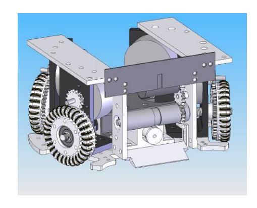
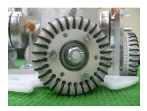
BROCKS Team Robots: Mechanical Specifications.
| Height of the robot | 143 mm |
|---|---|
| Maximum diameter of its projection onto the ground | 176 mm |
| Maximum percentage of ball coverage | < 20% |
Electrical Subsystem
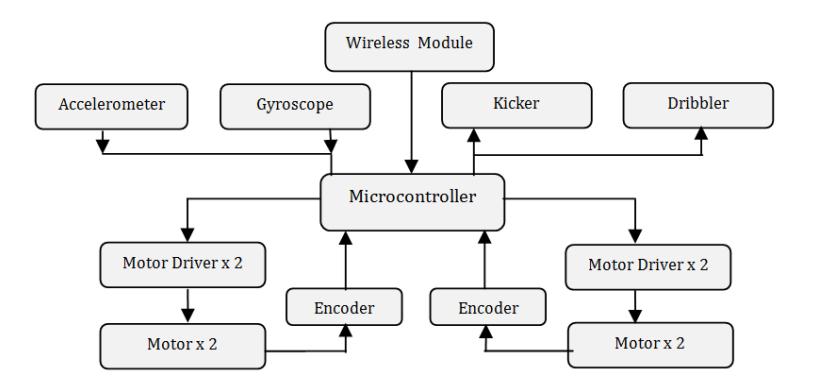
The electrical subsystem has been redesigned and developed this year. One of the significant advances in the new design is the change of microcontroller type and the number of microcontrollers in the circuit. Each of our robots relies on the following electronic circuits that receive commands from the software subsystem in order to perform the desired tasks:
- Locomotion Motor Control Circuit: Our robots consist of four custom–built omniwheels, each of which is driven by a 30 watt, 4370 rpm brushless DC motor. The microcontroller is used to estimate the motor speeds and a controller logic is implemented on the microprocessor for precise speed control. Also the current sensing circuit is implemented to protect the system against unexpected errors by limiting the current flowing through the circuit.
- Dribbler circuit: The dribbler consists of a 6 watt DC brush–type motor and it is driven by a simple H–bridge circuit that is controlled by the microprocessor.
- Kicker circuit: The design principle of our current kicker circuit is similar to other Robocup designs [1] in the sense that it relies on charging a capacitor to 160 V and then releasing the solenoid once the controlling computer sends the "kick" command.
- Main Board: For proper implementation of the control strategies on the robots, it is critical that data be communicated to the robots in a wireless fashion that do not violate the rules of Robocup SSL. To this end, we use Zigbee low power wireless communication modules. The control data generated by the main computer are sent to the robots using the wireless modules, which are then received and processed by the microprocessor to carry out the following tasks:
- (a) Measure and control the speeds of four brushless DC motors,
- (b) Activate the solenoid when required,
- (c) Activate and control the dribbler when required.
The new electrical subsystem design also includes encoders, a gyroscope, an accelerometer and IR sensors as additional sensors in order to get the speed data more precisely. Sequential digital circuit is used to detect the rotational direction of wheels. However, the associated control algorithms have yet to be implemented.
Low Level Control
The schematic of our low level control architecture onboard each robot is shown in Fig. 3. The primary task of the low level control unit is to control the motor speeds. The desired motor speeds are sent to the robot via wireless Zigbee transreceiver module from the remote PC. Microprocessor gets the motor speed data from the Zigbee trans-receiver module onboard and activate the speed control loop.
Brushless DC Motors
Maxon EC-45 Flat 30 watt Brushless DC Motors are used for the locomotion of our robots. The main idea for choosing this type of motor is that its small size allows us to use limited space more efficiently. The motors operate with 12V, at a maximum speed of 4400 rpm and can produce 59 mNm continuous nominal torque. 1:3 gear reduction ratio is used in order to increase the overall torque and three Hall sensors with 120 degrees phase difference are available from the motors for speed measurement. The Hall sensors in the motor produce a feedback signal that help estimating wheel velocities. Nevertheless, Hall sensors provide 48 pulses per revolution; therefore encoders which have higher resolution (1440 pulses per revolution) are implemented.
Speed Control
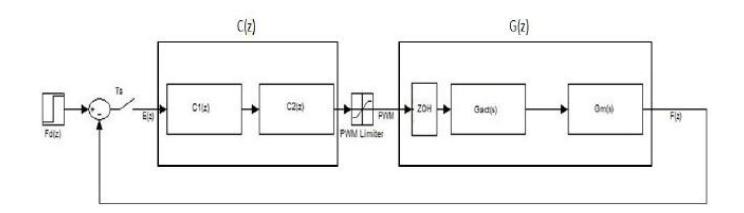
The speed regulation for each wheel is achieved using a digital controller that takes the reference and the estimated speeds as inputs, and adjusts the set point into the actuator. The complete block–diagram of the digital controller is shown in Fig 4 with the variables defined in Table 2 [4].
The design of the digital controller $C(z)$ depends on identification of the actuator and motor dynamics, i.e., $Gact(s)$ and $Gm(s)$, respectively. The speed regulation is realized using a digital PI controller whose parameters are chosen such that the closed loop pulse-transfer-function is stable, and certain transient performance specifications are satisfied. For more details, see [4].
Descriptions of the variables in Fig. 4.
| Fd(z) | z–transform of the desired wheel frequency |
|---|---|
| F(z) | z–transform of the estimated wheel frequency |
| C(z) | Digital PI controller |
| ZOH | Zero–order–Hold |
| Gact(s) | Transfer function of the driver circuit |
| Gm(s) | Transfer function of the motor |
| Ts | Sampling period |
Vision based control and coordination
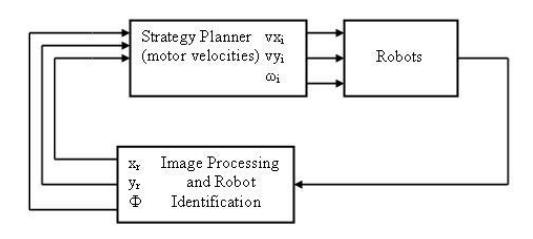
In this section, we describe the complete feedback system composed of autonomous holonomic robots that are equipped with wireless communication devices, two overhead cameras that can provide feedback on the robot positions, and a host computer that acts as a supervisor (see Fig. 5). The host computer receives/processes the vision data, and sends control commands to the robots accordingly. Our vision system consists of two 60 fps digital cameras which provide the visual feedback to the controlling computer. The SSL–Vision software provides the coordinates of the robots and the ball location via a graphical interface once colour and field calibrations are done properly based on the light intensity of the field.
High Level Control and Strategy Planner
High–level control of robot soccer team consists of two main modules:
- Strategy planning and tactics: The strategy planning is vital in multi–robot domains. Basically, the strategy planner assigns roles to each robot in order to complete a task, e.g., scoring a goal or defending its own goal. Team Agent Behavior Architecture (TABA) approach for dynamic task assignment and strategy is implemented (Fig. 6). The architecture consists of leader agent selection, strategy selection, role assignment and tactic execution. Role assignment is done according to the distance between robots and the ball. The primary attacker role is assigned to the nearest robot and this robot goes to the ball position. There are four types of roles which are primary attacker, offensive supporter, defensive supporter and the goal keeper.
- Motion planning and navigation: One of the main objectives when planning paths for multiple robots is to arrive at the destination point from a given initial point, while avoiding obstacles. There are various techniques used in path planning.
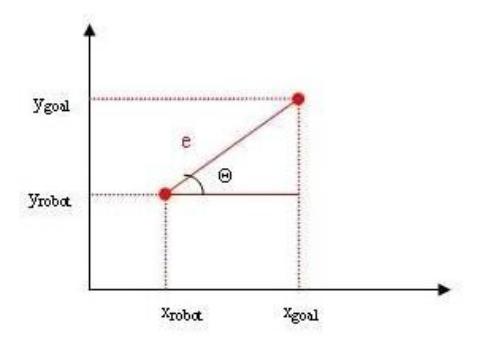
To briefly describe our methodology for the latter part, suppose that we set a goal point in the 2-D plane as shown in Fig. 7 [3, 4] . The location errors in $x$ and $y$ coordinates are defined as:
$$e_x = x_{goal} - x_{robot}, \tag{1}$$
$$e_y = y_{goal} - y_{robot}. \tag{2}$$
Using (1–2), we create a position error vector:
$$\Theta = \tan^{-1}(e_y/e_x),\tag{3}$$
$$|e| = \sqrt{e_x^2 + e_y^2}.\tag{4}$$
In order to direct the robot towards the goal point, we need proper velocity vectors in $x$ and $y$ directions. To this end, we have formulated the velocities in $x$ and $y$ directions as follows:
$$v_x = |e|\cos\Theta,\tag{5}$$
$$v_y = |e|\sin\Theta. \tag{6}$$
The velocities are proportional to the norm of the error vector that is the distance between the desired and current location of the robot. One important thing that needs to be considered is that, calculated velocities are relative to the global coordinates. In order to have the robot motion in the desired direction, we should transform these velocities relative to the robot's current orientation. This is accomplished by using the inverse of the rotation matrix in the $z$ direction:
$$Z^{-1}(\Theta) = Z^{T} = \begin{bmatrix} \cos \Theta & \sin \Theta \ -\sin \Theta & \cos \Theta \end{bmatrix}.\tag{7}$$
Finally, the commanded velocities are calculated as
$$\begin{bmatrix} v_{xrobot} \ v_{yrobot} \end{bmatrix} = Z^{-1}(\Phi) \begin{bmatrix} v_x \ v_y \end{bmatrix}, \tag{8}$$
where $\Phi$ is the orientation of the robot relative to the global coordinate system.
![Team Agent Behavior Architecture [5]](/tdps/soccer_smallsize__2011__BRocks/_page_6_Picture_0.jpeg)
Path Planning
Most path planning algorithms in real–time are based on the standard path planning approach [6]. Different from last year, the path planning system is based on well known RRT family of randomized path planners. The RRT planner searches for a path from an initial state to a goal state by expanding a search tree. It is also capable of acting in Robocup domain in real–time.
Multi–agent collaboration: The key issue in coordinating a team of robots during an SSL game is to decompose the complex task into simpler actions which might be referred to as modes and defining the transitions between these modes in some optimal way [7]. As the constraints and the goals of SSL are known, it is a well-defined environment for developing multi-agent strategies. On the other hand, it is still a challenging test–bed since two teams of robots compete with each other to win the match. The robots should work collaboratively in order to reach success. To this end, we intend to adapt 3 different approaches in developing our multi-formation algorithms:
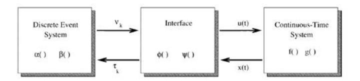
- Hybrid systems based formulation and control: A hybrid system is a dynamical system whose behavior develops as the result of a continuous state system interacting with a discrete event system (See Fig. 8). We will use hybrid systems in the design of low level and high level control algorithms.
- Market driven: The main idea of the market-driven approach is to apply the basic properties of free market economy to a team of robots in order to increase the gains of the team. In adapting the aforementioned technique to our system, we will define suitable metrics in order to select the proper actions at any given time [8].
- Biologically inspired: In the later stages of our software development, we also plan to extend and incorporate the biologically inspired method developed in [9] to our system.
Concluding Remarks
This paper gives an overview of BRocks 2011, covering the robot hardware and the software architectures. Participation in Robocup 2009 for the first time has helped us improve our team significantly. We look forward to competing in Turkey so that we can field a stronger team in Mexico City 2012.
Acknowledgements
This work is supported in part by the TUBA GEBIP Programme and by the Boğaziçi University Research Fund under contract number 5135.
References
- Robocup Systems Engineering Project, MS Thesis, Dept. of Electrical Engineering, Cornell University, 2002.
- F. Wiesel, Steuerung und Kontrolle von Omnidirektionalen Fussballrobotern, Diplomarbeit der Informatik, Freie Universitat Berlin, January 2006.
- H. Karaoguz, M. Usta, and M. Akar, "Design and Implementation of a Hierarchical Hybrid Controller for Holonomic Robot Formations" Proc. of the 10th International Conference on Control, Automation, Robotics and Vision (ICARCV 2008), Hanoi, Vietnam December 2008.
- H. Karaoguz, "Vision based control algorithms for a small size robot soccer team", MS Thesis, Bogazici University, February 2009.
- M. A. Ruiz and J. R. Uresti, "Team Agent Behavior Architecture in Robot Soccer". In Proceedings of the 2008 IEEE Latin American Robotic Symposium, Washington DC, USA, 20-25, 2008.
- O. Khatib, "Real–time Obstacle Avoidance for Manipulators and Mobile Robots", The International Journal of Robotics Research, 5(90-98), 1986
- H. Kose, K. Kaplan, C. Mericli, U. Tatlidede and H. L. Akin, "Market-Driven Multi-Agent Collaboration in Robot Soccer Domain", in Cutting Edge Robotics, (eds: Kordic, V.; Lazinica, A. and Merdan, M.), Germany, July 2005.
- C. Mericli and H. L. Akin, "A Layered Metric Definition and Validation Framework for Multirobot Systems," RoboCup International Symposium 2008, Suzhou, China, July 15-18, 2008.
- T. Mericli and H. L. Akin, "Soccer Without Intelligence," IEEE ROBIO, Bangkok, Thailand, February 2009.