CYRUS 2011 Team Description
Javad Amiryan, Armin Salimi, Mohammad Reza Ranjbar, Sina Raeessi, Reza Khoshkerdar, Mohammad Moallemi, Mostafa Nazari, Behrooz Shafiee
Electrical and Computer Engineering Department, Shahid Beheshti University, Iran
Abstract In this paper we have described various parts of Cyrus small size team. Hardware and software parts are divided into 4 sections and individually described. Mechanical section includes driving, kicking and dribbling systems. Electrical system contains two separate boards which provide control to motors and kicker. During design of Software system many factors such as efficiency, fault tolerance, extendibility and modularity were considered. Our software system follows a layered architecture. Using a layered architecture has many benefits such as extendibility, ease of use and flexibility.
Introduction
Cyrus small size soccer team, was formed about a year ago and is supported by faculty of electrical and computer engineering of Shahid Beheshti University- Tehran. We had our first experience of competing in the Khwarizmi Robotic Competitions-2010 where we were placed 4th. The team's purpose is to develop and implement artificial intelligent systems in the real environment. Some innovations in electrical and mechanical parts have been made for the second generation of our robots which are described in following sections.
Mechanical system
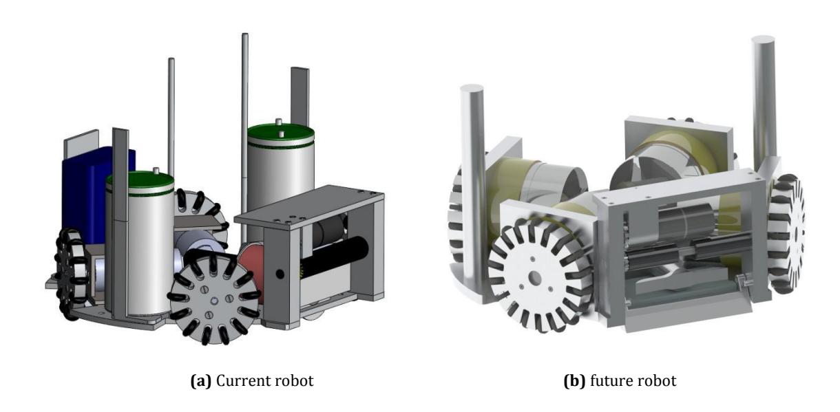
After the first generation robots, we made some basic changes in mechanical system, especially in kicking and dribbling parts. Each robot is 178mm in diameter and 138mm in height and at most covers 20% of the ball. Mechanical system includes driving, dribbling and kicking systems and a chassis. Each part is designed conceptually and separately and then simulated to reach the maximum performance. (Fig. 1 shows mechanical design of robots)
Driving system
Omni-directional wheels, Faulhaber DC motors equipped with encoders and motor mounts constitute the main components of this part. The angle between rear and front motors are equal to 90 and 114 degrees, respectively. These angles provide an appropriate acceleration and speed with a good performance in maneuvering. Each wheel is 50mm in diameter and has 13 subwheels to enable it to move in all directions properly; and also we have used maxon EC45 flat motors and Maxon GS45 gear heads in our new robots which enables them to have more acceleration and speed beside having 30 watts of power and being lighter than brush motors.
Kicking system
A linear kicker arm, a metal core and a solenoid form a system which can kick the ball in an arbitrary speed on a straight direction. Furthermore one flat solenoid has been designed to enable the robots to do chip-kick. We have used 0.7mm enameled wire in order to reduce the R/L ratio, thus making the solenoid to respond faster.
Dribbling system
A silicon coating bar has been used to enable the robot to catch the ball when it is passed and hold it before kicking. A DC motor has been attached to a spur gear with 2:1 gear ratio, which spins the bar at a speed of 4000 rpm.
Electrical System
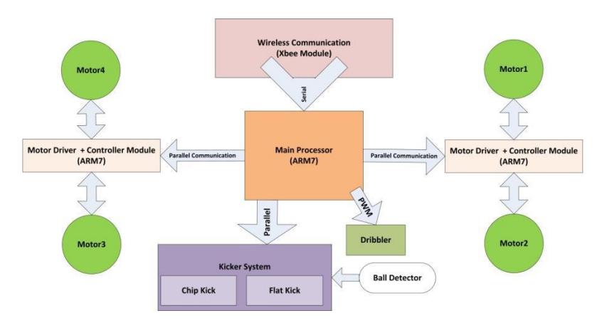
This system provides the controlling signals to the driving system and kicker module and consists of two separate boards called the main board and the kicker board, respectively. The main reason for separating these parts is to reduce the effect of electrical noise caused by boosting and kicking functions of the kicker board on the other parts. Data communications between the boards are implemented in a parallel way which results in no data loss during transmission.
Main Board
This board has the duty of receiving data via wireless module, analyzing it, and controlling the motors. It also sends commands to the kicker board as to determine the time and power of kicking. In addition some components are added to the main board to interface with the user such as push buttons, dip switch, LED and buzzer. One of the board's advantages is the ability of easy programming which can be done by USB port.
Wireless Module
AI commands sent from the host PC are received by an Xbee-PRO OEM RF module. This module has more transmissive power than an Xbee standard module and electromagnetic noises can not disturb its operation. It operates within the ISM 2.4GHz frequency band and provides reliable delivery of critical data between devices.
Processor Unit
The main board uses 3 ARM7 microcontrollers in order to communicate with the Xbee module via USART protocol, send commands to the kicker module and control the motors. Two slave microcontrollers receive commands from the master one, including direction and velocity of motors. Each of them handles controlling of two motors. Additionally, the controller is implemented by these microcontrollers. Each microcontroller is equipped with 3 Timer/Counter channel, so that the act of counting the pulses of encoder would be done without wasting any cycle in the processor which leads to performing fewer instructions in the processor. Moreover control loop would run at higher speed.
Motor Driver
As our motors consume low power (4.05W) and current, we use L6203 motor drivers which can drive DC motors with a maximum supply voltage of 48V and maximum operational frequency of 100 KHz. We have also used a 3 phase motor driver circuit to run BLDC motors. This circuit uses three N-channel MOSFETs, three P-channel MOSFETs and one IR2130 3-phase bridge driver.
Kicker Board
As mentioned previously this board receives commands from master microcontroller in main board and provides kicking the ball in different magnitudes. Another data which is used to determine when kicker acts is ball detection output.
Boost Converter
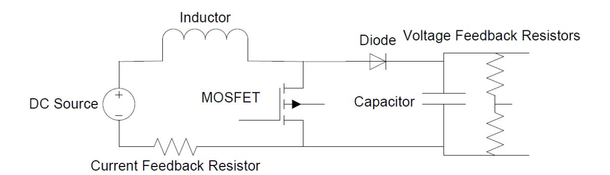
We have used a simple boost circuit topology with a current and voltage feedback on our robot's booster-kicker board. The booster charges two paralleled 2200 µF-250 V capacitors up to 240 Volts using a voltage feedback to measure the capacitors' voltage and a current feedback to adjust the switching duty cycle on a fixed frequency of 31.25 KHz. (Fig.3 shows booster circuit)
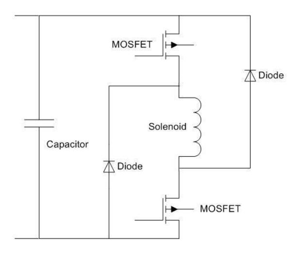
The kicker then, given the command, connects the charged-up capacitors to the terminals of our robot's kicker or chip kicker solenoid, causing it to suck in the magnetized steel core and shoot the ball. On the kicker part of the board we have adopted an asymmetric bridge topology which uses two switches to connect the capacitors to the solenoid and two diodes to return the currents when switches go off. Also shoot power can be adjusted by changing the duty cycle of the command PWM signal that goes to the switches.(Fig. 4 shows the kicker switches)
Ball detection
The presence of the ball and its situation should be verified before shooting because of some problems such as the delay of receiving AI commands or not having enough accuracy of the vision system. The ball detection module solves this problem and enables the robot to find out the accurate position of ball. One IR transmitter and one IR sensor are used to perform this task. Also a simple RC filter has been implemented to ignore environmental beams. The robot keeps looking for the ball for 1 sec if it couldn't find it after its been kicked.
Controller
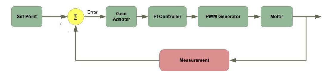
One of the most important parts of our robots is their controller firmware. By means of this the robots will move accurately and the software part would be able to make better decisions. As the DC motors can`t perform correctly in low speed due to their low power, and then we have implemented a digital controller on the main board's microcontrollers which can catch signals from the motors encoders and make proper signals to each one. As the encoders produce the square wave, their velocity can be calculated by measuring its period time. Measuring the correct velocity is difficult because of the high distortion of the waves, thus we need to measure it repeatedly. Then the desired PWM signal will be produced in a PI controller with adaptive parameter. One fuzzy system with a Takagi-Sugeno inference mechanism has been chosen for the parameters adaption. The block diagram of a closed-loop system is depicted in Fig. 5.
Software
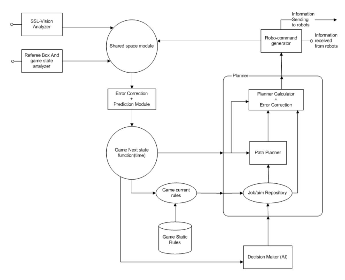
The main two goals in designing all software parts are achieving more accuracy (reduce error rate and prevent propagation of error in other parts) and making them as fault tolerance as possible, when errors can't be avoided. You can see the software architecture in (fig. 6).
The main modules are categorized in the four main layers:
- Drivers
- Planner
- Analyzer
- Decision Maker
This layer-modular architecture has three main benefits. First of all, it would isolate the layers (so that it avoids further conflict of the codes and modules). Second of them, it enables us changing module/layer by keeping the connector interfaces not disturbing other modules/layers. And at last, it makes it possible to work with some other proper modules (such as heterogeneous modules in Drivers layer for controlling different robots) compatible with module/layer of the program.
In the following sections, these layers are explained in details.
Drivers
Drivers is the primary layer of the software. There is SSL-Vision, Referee Signal and Robots Signal Analyzer modules and also Robot Control Signal Generator module in this layer. The results (outputs) of these modules are converted to application parameters (model of the world, or world model) and these parameters can be used in further modules depending on the situation of the game. Physical/Mathematical processes of the upper-layer knowledge including performing robot actions and sending orders to robots are both done here in robo-command generator layer.
Planner
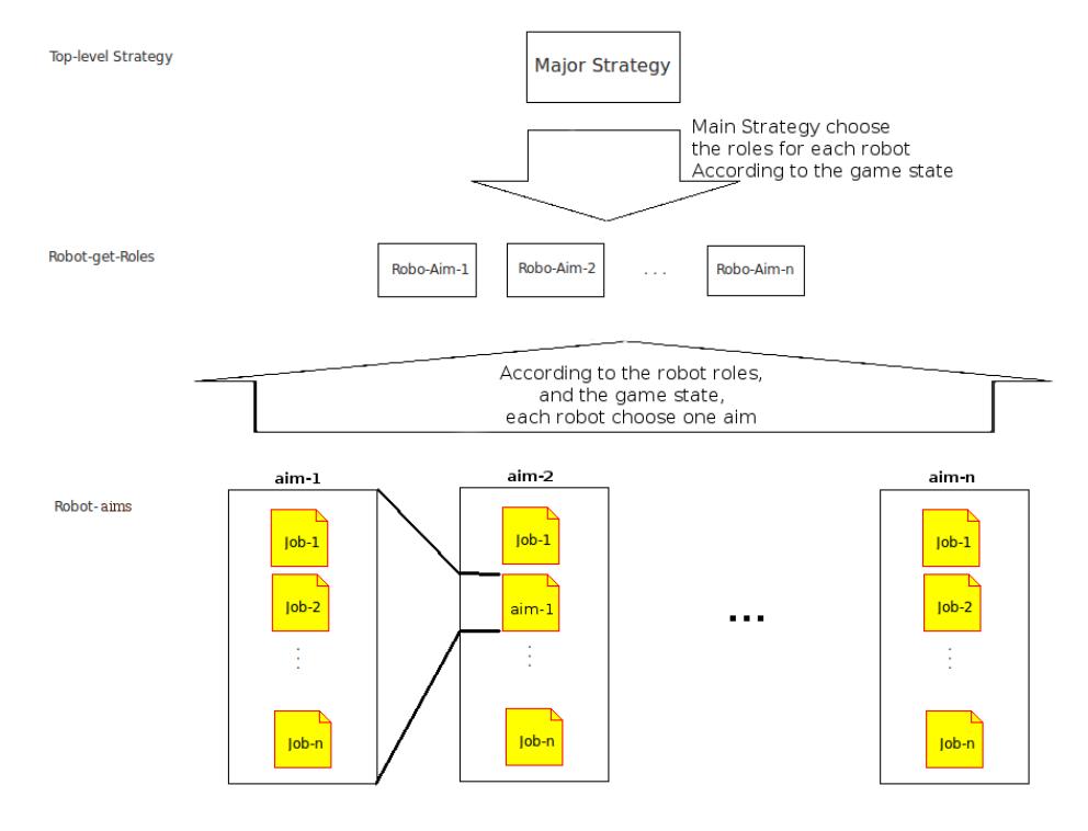
In the Planner layer, upper layer commands (called aim or job) are checked and converted to the under-layer orders to be performed on robots. Aim is an ordered collection of Jobs that satisfies the aim concept, and job is piece of task that tries to change the situation (by controlling the robots) in order to achieve its end point. The upper-layer provides aims, and the planner plans how to accomplish these aims. Checking the consistency of the aims/jobs, solving possible overlap of the aims, managing concurrency and order of jobs are the main processes in this layer.
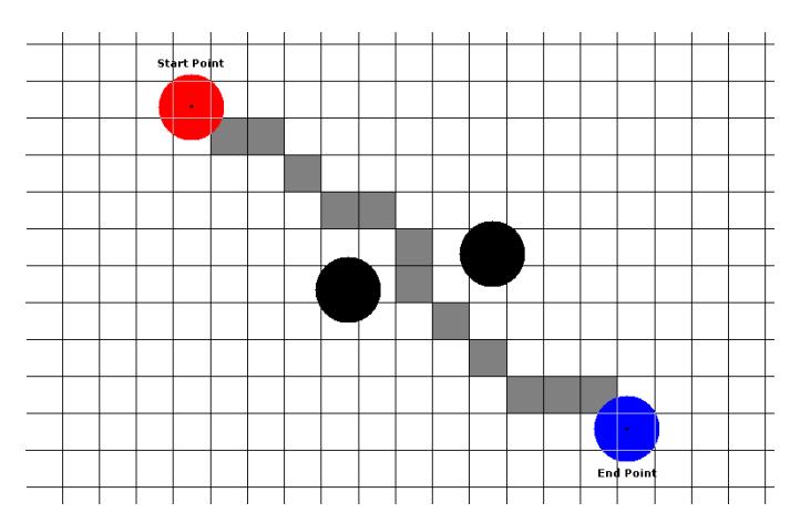
The path planner is the most important module of this layer. In this module, there are target points as a robot's targets and a current/next state of the game as inputs, and (Vx, Vy, ωz) of the robot, as output results. Path planner creates a grid map of the page and specifies the obstacles, and then finds the best path from robo-position to the target (by breath-first searching near direct line from robo-position to the target) and smoothes the path.
Jobs could have dependencies to each other. For instances, some jobs may expire if environment inconsistency happened in the game. Also job's target has great chance to change during the planning. In order to avoid this, Planner runs some checks (check with related rules and other jobs) before it performs that job.
Analyzer
In Analyzer layer, some calculation would perform on World Model data, to predict next state of the game, and make the upper-layer able to extract strategy of opponent team (for instance, find the opposite-ball-owner or opposite-shooter robot and position of shooting (start point) and target of the shooting (or pass). in this layer, some AI history-based systems are used for prediction. This prediction helps AI decision maker to choose proper strategy. Prediction module designed flexible; so that we could use different prediction system on it. (Available system used here is an ANFIS history-based system for robot-movement prediction)
Decision Maker
In this layer, strategy (long-term aim) and Jobs/aims are calculated according to the game current state and game predicted state. Proper decision is chosen via a Fuzzy Decision Tree. The major strategy is divided into three main categories "Attack", "Defense" and "Arrange" mode. The Decision Tree cuts into detailed job (or searching through designed aims according to heuristic function and game state) and the result is delivered to under layer (Planner) to accomplish the aims (Fig.8).
In attack/defense strategy, game graph is calculated according to distances between the robots, ball, and the goal, and less risky way would found and planned.
References
- Chitchanok Chuengsatiansup et al., "Plasma-Z Extended Team Description 2009", Robocup 2009, (2009)
- Muhammad H.Rashid, "Power Electronics Handbook", (1945)
- Jyh-Shing Roger Jang, "Adaptive-Network-Based Fuzzy Inference System (ANFIS)", IEEE Trans. on Systems, Man and Cybernetics (vol. 23), (1993)
- João Chaínho, Pedro Pereira, Silviano Rafael and A.J. Pires, "A Simple PID Controller with Adaptive Parameter in a dsPIC; Case of Study", 9th Spanish Portuguese Congress on electrical engineering, (2005)