ER-Force 2011 Extended Team Description
Florian Bauer, Michael Bleier, Michael Eischer, Stefan Friedrich, Adrian Hauck, Philipp Nordhus
Robotic Activities Erlangen e.V. Pattern Recognition Lab, Department of Computer Science University of Erlangen-Nuremberg Martensstr. 3, 91058 Erlangen, Germany
Abstract This paper presents an overview description of ER-Force, the RoboCup Small Size League team from Erlangen, Germany. The current hard- and software design of the robots and the motion control system are described. An insight in the software framework and strategy architecture is provided. Furthermore, upcoming changes and improvements are outlined.
1 Introduction
This paper describes the German RoboCup Small Size team ER-Force from the University of Erlangen-Nuremberg. The team was founded in fall 2006 by students from various engineering disciplines, such as computer science, mechatronics and electrical engineering. It is still an interdisciplinary project with around twenty members. In 2007 we founded a non-profit association called "Robotic Activities Erlangen e.V.". This association is engaged in many robot-related activities including the support of two Robotics groups at local high schools. The team participates at the international competitions of RoboCup since 2009.
The following sections provide an overview of our current Small Size League team. In Section 2 the hardware and firmware architecture of the robots is described. We discuss the hardware of our 2010 system and outline the new developments that will improve our 2011 system, e.g. the modular design that we are going to use as it turned out to be very complicated changing components that are located in the lower part of the robots. The motion controller used is described in Section 3. In Section 4 we examine the software architecture. The different submodules such as a simulator and pathfinding are shown as well as a short overview of the radio communication protocol. The techniques applied for filtering and tracking of the position data provided by SSL-Vision are presented in Section 5. The strategy module and decision algorithms implemented in our system are described in Section 6. Besides we are going to present on RoboCup 2011 a new SSL-RefBox, that is specified in Section 7. It will provide a more clearly arranged user interface and will also work under lower screen resolution, what had often been a problem.
2 Hardware
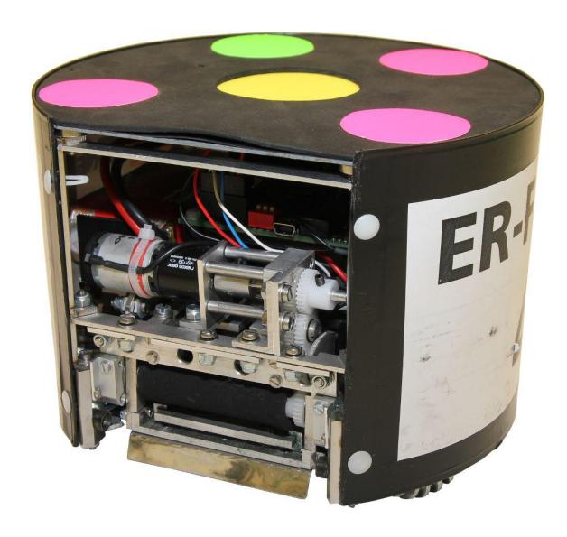
In the following section we will describe some parts of our hardware in detail. We employ six robots that are identical in construction. Each robot features a omni-directional drive with a solenoid kicker system. Fig. 1 shows our robot design from 2010.
2.1 Modular Design
Firstly, we want to present the design pattern used for this year's robots. When planning the new hardware of the robots for RoboCup 2011 in Istanbul, we persistently pursued the approach of a modular design. A modular system is characterized by the following features:
- The system is partitioned into several discrete, scalable and reusable functional blocks. Every block fulfills some specific functionality and that independently from other blocks.
- The interface between a set of blocks is well defined. The relationships of two blocks can be mechanical, electrical, logical, ...
- International industry standards are used for key interfaces where possible.
Compared to our previous construction style, strict modularity offers some decisive advantages:
- Hardware partitioning eases team-work in development and construction
- If only a part of the robot has to be modified (because of malfunction, improvement, or other reasons), the rest of the system will stay untouched.
- Cost reduction because of the avoidance of non-standard interfaces and the reusability of decent parts
Talking in terms of our robots, modularity means:
- The mechanical skeletal structure of the robot accommodates 4 drive units, the kicker device and the main controller.
- Every drive unit consists of a mechanical framework fitting into the skeletal structure, the brushless DC motor itself, encoders to determine the wheel movement and an electronic device that controls the motor. This contrasts significantly to our old robot design – now, all components needed to drive one of the wheels are combined into a single, reusable and discrete unit.
- The kicker unit is located in the center of the robot and points to the front side in order to kick the ball.
- All boards on the robots communicate via a consistent bus system. As we gained positive experiences with the CAN (Controller Area Network) bus in the last year, we are favoring CAN as communication line between the boards.
This architecture will help us to repair our robots quickly if needed in the contest. Until now, if a robot was damaged, we had not only to locate the problem on the robot, but to disassemble the robot completely in order to repair the faulty item. In our new design, we simply have to replace the corresponding module by a new one of the same kind. As a consequence, the robot will be operational again in less time and we can afterwards focus on repairing the module unhurriedly. Furthermore, we don't need a complete robot as replacement but only some modules as backup. Cost savings and an increase in system reliability are obvious.
2.2 Drive and Kicker
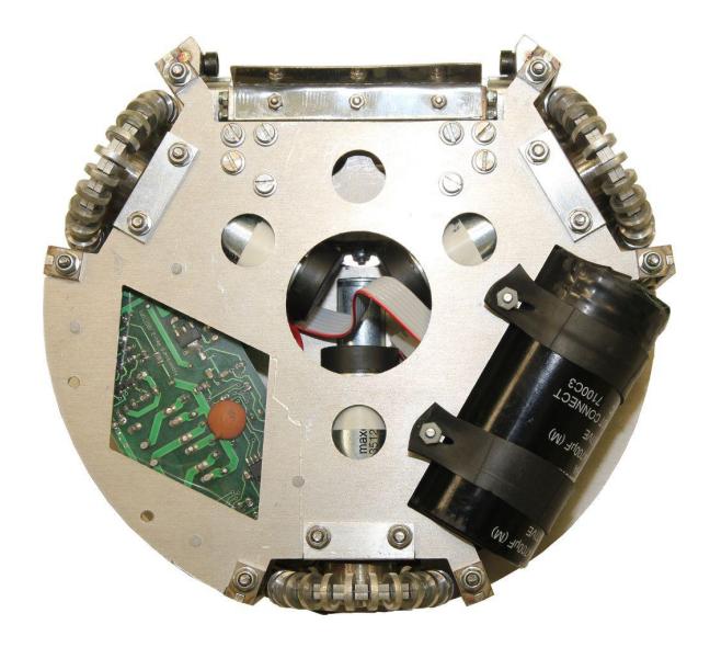
This year we have upgraded our driving system to four brushless DC motors (Maxon EC 45 flat) with four omni-directional wheels. The new motors have more power and a higher efficiency than the old brushed motors, which will result in a higher maximum speed. Fig. 2 shows the three wheel drive of our 2010 design.
We currently employ a solenoid kicker, which consists of a high voltage capacitor with a capacity of 4900 µF and a solenoid with a resistance of 1.5 Ω. The capacitor is charged by a step-up charging circuit to a voltage of up to 200 V. To activate the kicker a Power MOS-FET is used to drive the high current and voltage load. The current system is capable of shooting the ball at a speed of up to 8 m/s. A chip-kicking device using the same capacitor but a second solenoid was developed in 2009 and is still in use. We are currently redesigning the the kicker mechanics with a larger solenoid to make the mechanism even more robust and to increase the maximum ball speed.
The dribbler system in our robots from 2010 is placed above the kicking device. It consists of a rubber coated bar driven by a small DC motor (Maxon A-max 19). This bar was designed to exert backspin on the ball and keeping it in position. This dribbler design proved to be insufficient, as it is almost impossible to receive passes with a stationary mounted dribbler. Therefore, we are constructing a passively damped dribbler bar which slows the ball down when it hits the robot. This should facilitate passing the ball at high speed.
2.3 Electronics
In the development of the robot electronics we continue the modular design pattern. We decided to divide the electronics in to various boards in order to reduce the amount of necessary connectors and cables, simplify development, and make the system more robust in terms of electromagnetic compatibility. A main board runs the motion control and radio communication, and provides an USB interfaces for debugging purposes and programming of the embedded systems. Each motor is equipped with a drive board that runs torque and speed control for each BLDC motor. The kicker board uses a step-up converter to charge a capacitor to a voltage of up to 200 V and drives the solenoids. This is one of the most demanding parts of the electronics since during a shot a peak current of more than 100 A flows through the solenoid. Each board features a ARM Cortex-M3 microcontroller, which is connected to the CAN bus. We employ the CAN bus for data communication between the main board, kicker and motor boards, as well as for uploading the software to the microcontrollers. For communication with the strategy software running on the PC we use different types of radio transceivers, such as the NRF24L01 (2.4 GHz ISM band) or the RFM12 (434 MHz and 868 MHz ISM band). In our 2010 implementation the communication was only one-way from the computer to the robots. This will be improved in our new design by integrating status packages sent from the robots to the strategy computer.
3 Motion control
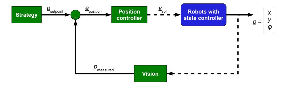
To allow smooth motion of the robots the positions generated by the strategy need to be processed by a motion controller. The position controller (see Fig. 3) gets the current position of the robot $p_{\rm measured}$ from the vision system, compares it to the desired position $p_{\rm setpoint}$ and calculates the postion error $e_{\rm position}$ :
$$e_{\text{position}} = p_{\text{setpoint}} - p_{\text{measured}}$$
(1)
This is used to calculates a setpoint for the velocity of each robot:
$$v_{\text{setpoint}} = \begin{bmatrix} v_{x, \text{setpoint}} \ v_{y, \text{setpoint}} \ \omega_{\text{setpoint}} \end{bmatrix} = K_p e_{\text{position}}(t) + K_i \int_0^t e_{\text{position}}(\tau) d\tau + K_d \frac{d}{dt} e_{\text{position}}(t) .$$
(2)
Each velocity setpoint is then transmitted to the according robot. The velocity needs to be controlled by the control software running on the microcontrollers of robots.
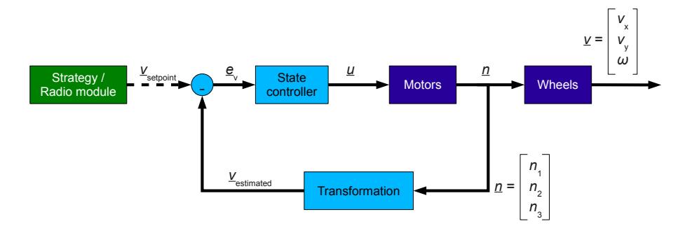
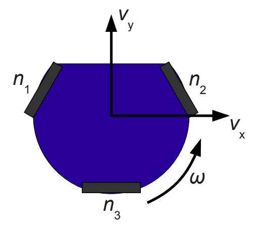
The simplest way to control an omni-directional drive-system is to control each wheel individually with a simple PID controller. Since 2010 our new approach for the motion control is to use a state controller, which takes the rotational speed of all wheels into account. It then controls the velocity of the robot as outlined in Fig. 5. The three state variables are the velocities of the robot in x and y direction and the angular speed. The used coordinate system is shown in Fig. 5. The actual controller implemented in our system is a PI state controller. Currently we cannot measure the velocity of the robot directly but we measure the rotational speed of each wheel and transform it into velocities. The problem with this approach is that the wheels can slip and the velocity is measured wrongly. A new idea to improve the velocity estimate is to use laser motion sensors which are capable to measure the velocity of the robot directly.
4 Software Architecture
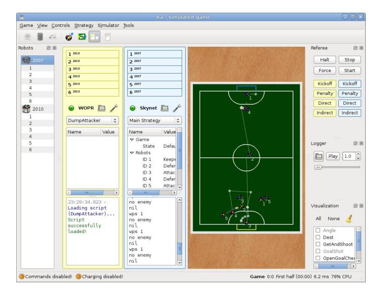
Our Software framework (see Fig. 6) uses a single application consisting of multiple modules. Most of the modules are written in C++ using the Qt Toolkit. The framework currently has these modules:
- Tracking: Tracking is described in detail in section 5.
- Simulator: Our simulator is based on the Open Dynamics Engine. It tries to simulate the behavior of our real robots as best as possible. While it is far from being perfect, it works good enough for testing our strategies.
- Strategy: This module allows the whole strategy to be implemented in LUA [1] scripts. A simple C++ ↔ LUA interface allows the scripts to access the result of the tracking as well as passing commands to the robots. Script files can be automatically reloaded when changed even during a (test) game, so that changes can be immediately tested. To show debug and status information in the UI, the scripts can use a log window and a TreeView to dump LUA tables. It is also possible to define configuration variables, which can be changed in the UI. To optimize the runtime performance, we use a just-in-time compiler for LUA.
- Pathfinding: A utility for our strategy to generate ideal way points. This module was part of the strategy written in LUA, but was optimized in C++ for performance reasons.
- Logging: A flexible logging mechanism that dumps all incoming data from the vision and referee system. These logs can be replayed later and allows extended debugging and game analysis. We plan to extend the logger with debug and status information from our strategy to be able to exactly reproduce any bugs which occur in a game.
- GUI: A Qt based user interface which shows all information of the framework in a single window.
- Radio: Responsible for communicating with our robots.
Logging, simulation and a script based strategy form compose a quite powerful tool, which allows rapid testing and debugging without the need for time consuming recompilations and without requiring to have ten working robots for every test run.
4.1 Radio Communication
We are using a two way communication to our robots. In each iterative step our strategy module (described in Section 6) updates the destination positions for the robots. The relative movement speed (in robot-local coordinates) is calculated, and sent via USB to a radio sender module. To simplify the communication we have implemented a small C library which can be used in the C++ strategy application as well as on the radio transceiver itself. It focuses on three aspects:
- Same source code on strategy computer and robots
- Small packet sizes to keep latency low
- Forward compatibility to be able to use robots without reprogramming them after a protocol extension
The feedback channel is used to report battery level, light barrier state, and other system information from the robots to the control computer for visualization.
5 Tracking
In previous years each team had to setup its own camera system and implement their own segmentation software to acquire positions and orientations of the objects in the field. Since RoboCup 2010 Singapore, however, the vision in the Small-Size League is centralized. Position and orientation data is sent to both teams by a single computer running the SSL-Vision software [2]. Given that SSL-Vision only detects objects without performing any filtering or tracking, this information can be unreliable.
5.1 Vision Problems
Common problems include:
- Changes in lighting
- Camera flashes
- Multiple balls, e.g. by misdetection of pink markers
- Ball occluded by a robot
To cope with these problems a multiple target tracking algorithm has been implemented in the ER-Force software framework. It provides multi-sensor fusion from the two camera images, tracking over misdetections, and filtering to compensate for image noise.
5.2 Data Association
A central process in Multiple Target Tracking is data association. At each tracking time step k there are M measurements from SSL-Vision $\mathbf{y}_k^j$ which have to be associated to N targets $\mathbf{x}_k^i$ . The number of targets N is variable and can change between iterations by births and deaths. A birth occurs whenever a measurement could not be matched to an existing target. In this case the number of targets is increased by one $(N \to N+1)$ and a new target is created and initialized from the measurement. When a target has not been associated with a measurement for a given period of time, the target dies. The number of targets is decreased by one $(N \to N-1)$ and the target is removed.
5.3 Estimation
The association process for robots is entirely based on the robot's id and position. Whenever a robot measurement is within a certain radius of a previously known robot target with the same id, that target is updated by the measured position.
$$\mathbf{p}k = \mathbf{p}{k-1} + \mathbf{v}_k \cdot t$$
(3)
To remove any outliers from the measurement the sample median filter [3] is applied. The last R velocity estimations are sorted and only the median value $\mathbf{w}_k$ is considered for further processing.
$$\mathbf{w}k = \mathbf{u}'{\frac{R+1}{2}}$$
(4)
The result from the median filter can still change very rapidly between two frames. These changes can severely interrupt the control loop in the strategy. Therefore a mean filter is applied, to smooth the velocity.
$$\mathbf{v}k = \frac{1}{S+1} \left( \mathbf{w}k + \Sigma{s=1}^S \mathbf{v}{k-s} \right)$$
(5)
If a robot is not detected at the current time step, its velocity is assumed to be identical to the previous step (vk = vk−1) while its position pk is updated only by this velocity as shown in equation 3.
The estimation of the ball speed and velocity is currently identical to that of the robots. An incorporation of the friction of the ball is planned until RoboCup 2011 to improve the estimation of an intercept position.
6.1 Overview
Beside the improvements in other sections we are currently redesigning the strategical behavior of the ER-Force robots. In order to make better use of all available players on the field we created a strategy consisting of multiple layers. Each layer uses a consistent interface allowing us to easily add further tasks. The low-level-tasks like passing, shooting on goal or defending provide some basic skills that can be used by higher-level-tasks. A single task can handle multiple robots allowing them to play together. The advantages are various: any improvement must be edited only once in these tasks instead of various times in the higher-level-tasks; these are kept slender and well arranged. Due to the division in layers the low-level-tasks can even reuse each other. To shoot a goal for example the task relies on a generic shoot task that is also using further low-level-tasks. Thus any improvements in the shoot task are also present when shooting a goal. In order to provide powerful passing it is now explicitly modeled as a task, allowing the higher-level-tasks to have two robots work directly together. Additionally, by providing these highly reusable tasks it is easy to copy strategic moves from other sports like soccer.
A complex build-up of the game after acquiring the ball is possible in different alternatives in behavior of the players. The artificial intelligence decides itself, which variation seems to be best depending on the current position of our own and the opponent's robots or even on the success of an earlier try of this move. This estimation must be kept, even if another move emerged to be more hopeful. Only in the case of complete inefficacy another move has to be tried. This procedure avoids a permanent switching between different complex moves on assuring at the same time that a change of strategy is preferred to an unnecessary loss of ball. The analysis of the chance of success of a specific move requires much research and testing and is a long term project. To handle referee commands specialized behaviors are used which immediately take priority over the active behavior. As moves are dynamically chosen we are able to train the team by adding a new move. This allows us to use weaknesses of other teams which can be found on analyzing the opponent's behavior. It can be done by a human before a game or during breaks or by the strategry using the observer (see section 6.3).
6.2 Low-level tasks
Each low-level task handles a specific behavior. Available roles are
- Move to: provides move function for other tasks
- Move to ball: catches the ball
- Move with ball: handles dribbling
- Keeper: defends the goal
- Defender: helps the keeper to protect the goal
- Marker: marks a robot to intercept passes
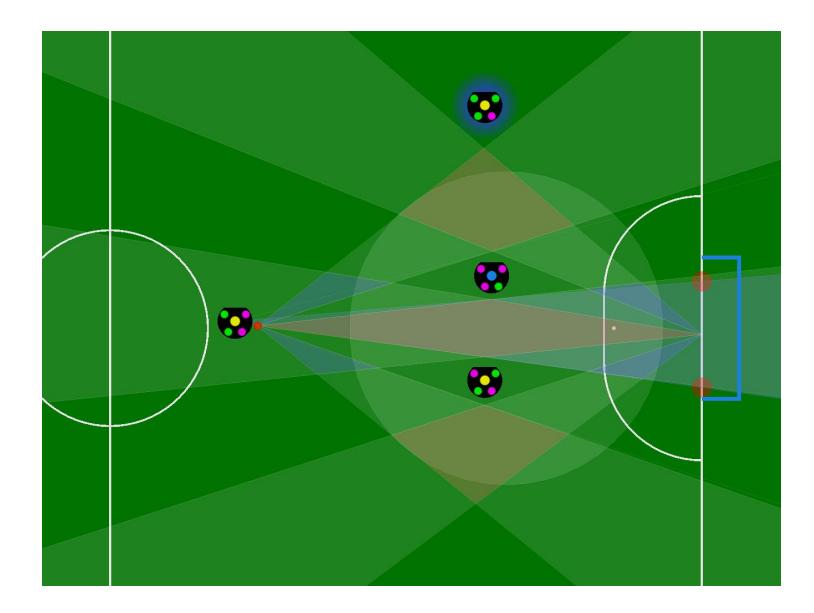
- Assistant: searches for a free space for passing (see Fig. 7)
- Shoot: handles shooting
- Shoot goal: shoots at the goal
- Pass: controls two robots and plays a pass
- Penalty-taker: specialized shoot task for penalties
- Penalty keeper: keeper optimized for penalties
6.3 Observer
Parallel to the role assignment and execution, an observer analyzes the match by gathering game play statistics. These include general referee information, ball specific information and player specific information:
- Referee information
- Number of goals per team
- Number of direct/indirect free kicks per team
- Number of penalty kicks per team
- Ball specific information
- Ball's average position and variance
- Ball's average speed
- Player specific information
- Each player's average position and its variance
- Average position of all robots of a team
- Number of shots
- Number of shots towards a goal
- Number of successful ball interceptions and ball passes
For this purpose, it is necessary to interpret the opponent players' behavior. Therefore, the observer recognizes events such as kicking the ball, grabbing the ball, passing the ball or intercepting the ball. For all of these events some conditions are specified to recognize them. For example the following conditions have to be fulfilled for the event kicking the ball (player P) in a time interval [t−1, t]:
- The ball has been in a specified orbital region around P (the radius is depending on the ball's velocity).
- The ball's moving direction has been changed significantly.
- The ball's speed has been increased.
6.4 Enhancements
The observer provides statistical information on the game flow. Using this information in medium level functions and high level functions (for defining the robots' behavior) leads to remarkable improvements. The analysis of the game refers to both the opponents activity and the overall situation. The role assignment and skills can take these aspects into account for planning tactical moves of the own robots. Besides this, the system is able to react to damages of our own robots, e.g. by swapping the roles of a robot having a broken chip-kick device with another robot.
7 Referee Box
One of the most important tools for refereeing a Small Size League game is the referee box. It is used to translate the commands of the main referee into machine readable information. However, the software that is currently used in the Small Size League has some drawbacks. The interface does not scale very well on low resolution screens. It is difficult to keep track of yellow cards and it is not possible to revoke commands easily. Since the protocol was designed primarily for serial communication, it was optimized for size and does not provide all the information that is available in the referee box. For example, the teams have to count their timeouts themselves. As a lot of teams have not implemented a visualization for the referee commands, they need to ask one of the referees, which is quite difficult during a game.
Therefore, we decided to rewrite the referee box software. We decided to implement the graphical user interface using the Qt framework. An alternative to the official referee box protocol is implemented using Google's protocol buffers. The new referee box is fully compatible to the currently used software and protocol, but provides some extensions to make the job of refereeing a game easier. We will also provide an example receiver and classes, such that the new protocol can be easily adopted. The software is mainly developed using GNU/Linux, but it works also on the Windows and Mac OS platform. A first demo will be released shortly after the publication of this paper.
7.1 Graphical User Interface
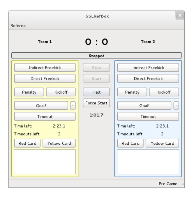
The new referee box was designed to allow easy access to all important functions with either mouse or keyboard. The layout was restructured in order to be able to access the most common commands with as little mouse movement as possible. A notification area was added to remind the referee assistant if robots may reenter the field of play or the time is nearly over. Support for tracking multiple yellow, or red cards was implemented. Fig. 8 shows the current version of the graphical user interface of the referee box.
7.2 Referee Assistance System
The games in the Small Size League tend to be very fast and most teams are able to shoot the ball at a high speed. Today it is already a tough job to referee a game. It is hard to tell which robot was the last to touch the ball, and if the ball actually entered the goal or hit the goal post. Therefore, we added support for SSL-Vision to the referee box. We plan to add support for plugins, which allows the community to easily extend the referee box. Using the SSL-Vision data we can track if a ball actually entered the goal or visualize rule infringements, such as multiple defenders, or non-rule compliant robot interchanges.
8 Conclusion
The current hardware design we presented in this paper is very similar to the one we used last year at RoboCup 2010, as most components proved to be very reliable. However, we are also planning to improve some parts as the kicker and the drive and we want to test a lot of new concepts like a two-way communication link. Major improvements, however, are present in the software of our system.
The strategy software was greatly improved, as we are integrating roles that involve multiple players. This was done to allow better robot interaction. Moreover, we did a lot of work on the role assignment algorithms. By analyzing the robots behavior and collecting statistical game data it is possible to react in a much more precise way to the opponent. We also implemented an improved tracking algorithm for robots and ball positions.
As we presented a lot of improvements we are eager to test them at RoboCup 2011 in Istanbul.
References
- Ierusalimschy, R.: Programming in Lua. Lua.org (2006)
- Zickler, S., Laue, T., Birbach, O., Wongphati, M., Veloso, M.: SSL-Vision: The Shared Vision System for the RoboCup Small Size League. RoboCup 2009: Robot Soccer World Cup XIII (2009) 425–436
- Gonzalez, R., Woods, R.: Digital Image Processing. 3rd edn. Prentice Hall (2007)