Eagle Knights 2010: Small Size League
Carlos Alegr´ıa, Paolo Aguilar, Alan C´ordova, Hip´olito Ruiz, Alonso Sol´ıs, Marco Morales
Robotics Laboratory, Department of Digital Systems, College of Engineering, ITAM, M´exico City, M´exico
Abstract In this paper we describe the design and implementation of the Eagle Knights 2011 Small Sized League RoboCup Team. We explain the design of the AI and Robot System. We discuss our seventh generation of robots that works with our previous team architecture. In addition, we describe the basic elements of a new action planning system that we will be using this year.
Introduction
RoboCup [1] is an international joint project to advance research on artificial intelligence and robotics through a grand challenge: design a team of robotic soccer players able to defeat the world champion team by 2050. The Small Size League aims to this challenge by promoting research on multi-agent cooperation and control. Thus,
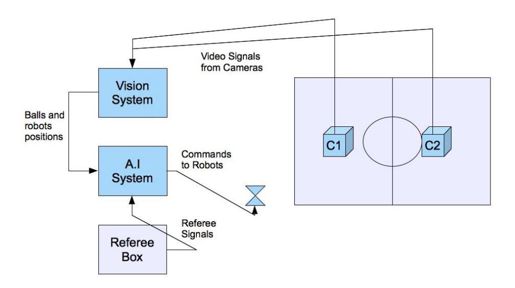
In the Small Size League, two teams of five robots up to 18 cm in diameter play soccer on a 4.05 by 6.05 m carpeted soccer field. As shown in Figure 1, aerial cameras send video signals to a shared vision system[2] that estimates the state of the robots and of the ball. Then, based on the state of the game, robots and ball, an AI system generates the control commands and sends them to each robots through a wireless link. The state of the game is maintained by an external referee box.
The robot architecture of our team in the Small Size League (SSL) consists of four main components: (1) shared vision system, (2) AI system, (3) robots and (4) referee:
- The shared vision system, SSL Vision[2], digitally processes two video signals from the cameras mounted on top of the field. It computes the position of the ball and robots on the field, including orientation of robots in our team. Resulting information is transmitted back to the AI system. We are using the SSL Shared Vision System since 2010.
- The AI system receives the information from the vision system and makes strategic decisions. The actions of the team are based in a set of roles (goalkeeper, defense, forward) that exhibit behaviors according to the current state of the game. These behaviors are encoded as rules of an expert system. A geometrical exploring tree is used to avoid collision with robots of the opposite team [3]. Trajectories are computed based on splines. The AI system sends commands back to the robots through a wireless link.
- Five robots, execute commands sent from the AI system by generating mechanical actions in a 60 times-per-second cycle. Each robot satisfy the constraints set in the SSL rules: they fit inside a 180 mm diameter cylinder and have a height of less than 150 mm, they ensure that more than 80% of the area of the ball when viewed from above is always outside their convex hull.
- The referee can communicate additional decisions (penalties, goal scored, start of the game, etc.) sending a set of predefined commands to the AI system through a serial link.
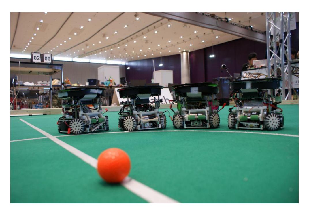
In the next sections we describe in more detail each component of our team. Our current system is based on our prior generation of robots (Figure 2) [4–7] with a completely reviewed electronics platform.
Shared Vision System
In 2010, the SSL League started using a new shared vision system, SSL-Vision[2]. It is the only source of feedback in the system architecture. The vision system should be robust enough to compensate for errors since the overall performance of the team depends on it.
The main object features used by the vision system are the colors defined in the rules of the SSL [1]. The ball is a standard orange golf ball. Each robot has a 50-mm circular patch, this patch is blue in one team and yellow in the other team.
The main tasks of the vision system are:
- Capture video in real time from cameras mounted on top of the field.
- Recognize the set of colors specified by the rules of the objects of interest on the field (robots and ball).
- Identify and compute the orientation and position of robots in the team.
- Compute the position of robots of the opposite team.
- Track the objects on the field and compute their moving vector.
- Transmit information to the AI system.
- Adapt to different lighting conditions (color calibration procedure).
In the past we have implemented a number of algorithms to make our system more robust to different light conditions. These algorithms include the use of a neural network to classify camera image pixels to a discrete set of color classes that is robust under different light conditions[8].
AI System
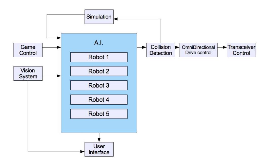
The AI System comprises eight modules: artificial intelligence, simulation system, collision detection, transceiver communications, robot control, user interface, vision system communications and game control.
The AI system includes a main thread that loops and calls each of the different modules as shown in Figure 3. The detailed description for each of the modules follows below.
- Vision System Communications This module provides information about the state of the game scenario corresponding to the position, angles and motion vector of the robots and of the ball. This information is provided through packets.
- Game Control This module receives referee commands through a serial interface and returns the game state of the game. For 2008 RoboCup we successfully tested the Ethernet interface both modes are available.
- AI This module receives the position and orientation of all the objects in the field (robots and ball), game state, robots roles. It estimates the future position of each robot and the actions they should take. A Kalman Filter is used to estimate the heading of the ball. The strategies are programmed as rules on an expert system. Each rule encodes the actions that each robot can take in their assigned role: goalkeeper, defense, first forward, second forward, and third forward. For example, defense and goalkeeper rules are defined to block the ball from its moving path, while second forward rules are defined to try a pass to the first forward, and first forward rules are defined to shoot to the goal. The expert system organizes the rules into a tree and assigns a score to each node based on the antecedents of the rule and its priority. The execution of the rule is a high level command for the robot to perform – e.g., passing, shooting, or blocking– that includes its linear and angular velocity and the use of the kicker and dribbler devices. These commands are converted into spline trajectories from which a speed vector is obtained for each robot to follow.
- Motion Planning This year we are introducing a new Motion Planning Module that incorporates our previous Collision Detection Module . This module has two components: a role assignment component and an obstacle avoidance component. This module is described in further detail in Section 3.1.
- User Interface This module constantly allows to visualize status information including: position, orientation and speed of the robot, game referee messages, control commands sent to the robots. It also allows to configure the AI system parameters.
- Simulation This module simulates robots and vision feedback in order to test system functions of the AI, collision detection and robot control modules without the actual vision system or robots being present. It allows to debug and test the artificial intelligence module. The field is visualized with a two or a three dimension graphics OpenGL[9] interface.
- Transceiver Communications Module This module builds the packets sent using our transceiver. The information sent to each robot is the moving vector and the angular speed of each robot.
Motion Planning Module
We are expanding the capabilities of our previous collision detection module to integrate motion planning into our navigation system. This module has two components: a role assignment component and an obstacle avoidance component.
Role Assignment
We are adapting motion planning techniques [10, 11] to perform dynamic role assignment in order to improve tactic decisions. This method receives the desired ball trajectory and state of the objects to produce trajectories for each robot. From the desired ball trajectory we compute a set of feasible plans that are ranked according to several criteria that include the relative position of the robots to the ball, their role, and their likelihood to help into moving the ball forward or to block it. The highest-ranked plan is chosen and executed. This method allows for planning from the perspective of the ball instead of the roles of the players. The goal is to better identify successful strategies. This method will be integrated with the expert system selection of actions through an arbitration process such that the motion plan is followed when it does not conflict with the expert system.
Obstacle avoidance
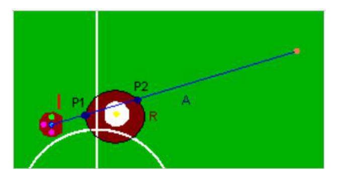
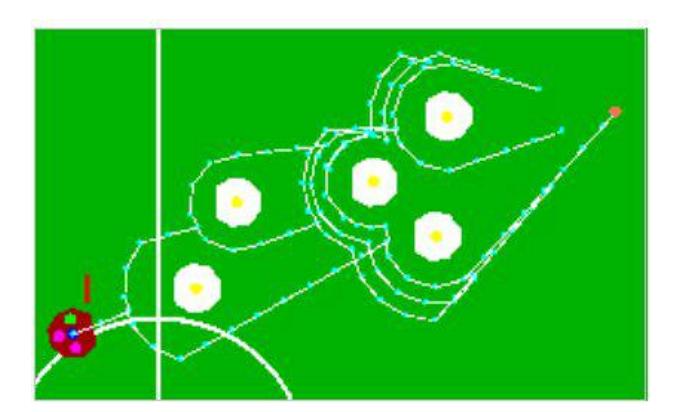
This module receives the current and goal robot configurations to generate a collisionfree path. A Rapidly Exploring Random Tree [12] variant, the geometrically exploring tree (GET) [6], allows us to achieve real time (five robots in more than 60 fps). Since the environment is highly dynamic, a tree encoding feasible motions is built in every iteration. Objects geometry is simplified to geometrical figures (circles for robots and rectangles for the goal). The tree starts with a root node for the current configuration classified as an exploring node. Then, it iteratively selects an exploring node from which it tries to reach the goal advancing a small predefined distance. Collision detection is performed with simple geometric tests as shown in Figure 4. If successful, the tree is extended and the new point replaces the last exploring node. In case of collision, the distance between the obstacle and the new extension is validated to be smaller than a radio "R".
In the example shown in Figure 4. there are two intersections: "P1" and "P2". When the tree reaches the radio "R", two nodes on each side of the obstacle are generated as exploring nodes. Exploration continues until the goal can be freely reached or another obstacle is found. In this case a new obstacle is defined as the exploring node obstacle and the process is repeated for the new obstacle as shown in Figure 5.
The algorithm works similarly for the goals. Once the tree has reached a point close enough to the goal the nearest path is chosen and the robot can be sent directly to the first point before intersection or in the direction of the next node towards the goal.
Robots
We designed and built six omnidirectional robots. Each robot has five Faulhaber 2224P0212 motors with gearheads 14:1 (four motors for the wheels and one for the dribbler) [13], a low resistance solenoid, a DSP – Digital Signal Processor, a transceiver, a single printed circuit board and two Lithium Polymer batteries. The height of the robot is 140 mm, the maximum diameter of its projection to the ground is 178 mm, and the maximum percentage of ball coverage is 19%. The robots were designed and manufactured using a the e-Machine Workshop software. The robot receives commands from the AI system in the PC. It includes the following functional elements:
Robot ID
Each robot incorporates an identification circuit manually setup with a dip switch that facilitates to modify the robot ID if necessary.
DSP
The robot micro controller is a Texas Instruments TMS320LF2812 fixed-point single chip DSP. This device offers low power and high-performance processing capabilities, optimized for digital motor and motion control. The DSP consists of six major blocks of logic: (1) External program and data memory, (2) I/O Interface, (3) Standard I/O, in addition to other modules not currently used in our design. The modules used are:
This year we are testing a new controller based on the Arduino open-source electronics platform. Also, we are using a new modular electronics platform that allows for easy replacement of driver boards for the motors.
External program and data memory The RAM module is used in debugging the software with the Parallel Port JTAG Controller Interface.
I/O Interface It contains different kinds of pins: (i) Capture units used for capturing rising pulses generated by the motor encoders which can be used to measure speed and direction of the moving motor. (ii) PWM outputs having an associated compare unit. A periodic value is established to determine the size of the PWM, and the compare value is used to change the duty cycle.
Standard I/O . It is used to read and write values for transceiver communication, motor, kicker and dribbler control.
Motor Control
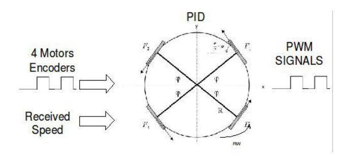
The motor encoders generate a number of square pulses for each completed turn. Each pulse is captured using the DSP and the feedback speed is computed into the omni directional-module. To control the motors speed a PWM signal sent back to the motor. This information is obtained by the omni-directional module.
Wireless Communication
Wireless communication is controlled by two Radiometrix RPC-914/869-64 transceivers with radio frequency at either 914MHz or 869MHz. The transceiver module is a self-contained plug-in radio incorporating a 64kbit/s packet controller with a parallel port interface. Data is transferred between the RPC and the host (either DSP or PC) four bits at a time using a fully asynchronous protocol. The nibbles are always sent in pairs to form a byte, having the Least Significant Nibble (bits 0 to 3) transferred first, followed by the Most Significant Nibble (bits 4 to 7). Two pairs of handshake lines REQUEST & ACCEPT, control the flow of data in each direction.
Omni-Directional Drive Control Module
This module receives the movement vector including linear and angular velocities from the transceiver. To control the motor speeds two steps are completed: (i) Speeds are read from the motor enconders. The speed of each motor generates the actual linear and angular velocities of the robot. (ii) These velocities along with transceiver velocities are used as inputs to the PID algorithm. There are three independent PID algorithms in the process: the linear speed projection in the x and y coordinates of the robot and the angular velocity. The output of the PID is turned into speeds for each motor (using the motors geometry in the robot) and finally they are controlled to the correct speed with a PWM signal. An illustration of the problem is shown in Figure 6.
Kicker Control System
Small Size soccer robots use different kicking designs to push the ball. We use a push type solenoid that kicks the ball. Solenoid kicker system needs a high power supply. For size restrictions robots have four 7.4V/ 700mA batteries, equivalent to 31 Watts of power. With this amount of power we obtain less than the solenoid requires for a minimum performance. The main idea in power elevation is to store energy, then discharge it when solenoid is activated. To solve this power problem we implement a four-layer system as follows:
Voltage transformation The 14.8 dc voltage obtained from the batteries is increased using a (Pico Electronics IRF100S) dc-dc converter [14] to reach 200 volts. The output is used to charge up two 2200mF capacitors. The converter is controlled using a control pin of the DSP with a relay and a transistor. The robot can kick approximately every 25 seconds.
Discharge and solenoid activation An infrared sensor system in the bottom of the robot senses if the robot has the ball. The DSP sends a high-level output bit when the robot is in score position. To discharge the capacitors into the solenoid, the Discharge layer uses both the DSP kick bit and the infrared ball detector output bit to discharge the capacitors. Because the capacitors charge level is very high, the robot discharges it using a power MOSFET. A signal from the DSP, is sent to the RELAY to control the flow of current through it and thus controlling the kick.
Conclusions
Here, we provide an overview of the software and hardware of the SSL Eagle Knights team. Our team has been the first Latin American team consistently obtaining top results in all its regional RoboCup participation, 3rd and 2nd place in US Open 2003 and 2004, respectively, and 1st place in Latin American Open 2004 and 2005. We have also participated in the last six RoboCup competitions: Osaka, Japan 2005; Bremen, Germany 2006; Atlanta, USA 2007; Suzhou, China 2008; Graz, Austria 2009; and Singapore 2010. We have released the Vision System and documentation of our electronics and DSP software to the public in order to promote the participation of other teams in this initiative. More information can be found at http://robotica.itam.mx/.
Acknowledgements
This work is supported by the Asociaci´on Mexicana de Cultura, A.C.. The framework presented here builds upon the continued effort of current and previous members of the team including its former leader Alfredo Weitzenfeld.
References
- RoboCup SSL, laws of the F180 league 2010. http://small-size.informatik.uni-bremen.de/rules:main.
- S. Zickler, T. Laue, O. Birbach, M. Wongphati, and M. Veloso. SSL-Vision: The Shared Vision System for the RoboCup Small Size League. RoboCup 2009: Robot Soccer World Cup XIII, pages 425–436, 2009.
- Basu A. Elnagar, A. Local path planning in dynamic environments with uncertainty. pages 183 –190, Oct 1994.
- L.A Mart´ınez-G´omez, F. Moneo, D. Sotelo, M. Soto, and A. Weitzenfeld. Design and implementation of a small size RoboCup soccer team. In 2nd IEEE-RAS Latin American Robotics Symposium, Sao Luis, Brasil, 2005.
- David Sotelo. Design and implementation of ITAM's F-180 robots. Technical report, Digital Systems Department, ITAM, Mexico City, Mexico, 2006.
- Ernesto Torres. Coordination strategies for multi-robot systems in RoboCup small-size league. Technical report, Computer Engineering Dept, ITAM, Mexico City, Mexico, 2009 April.
- Jes´us Rodr´ıguez. Robotics architectures for the RoboCup small-size league. Technical report, Computer Engineering Dept, ITAM, Mexico City, Mexico, June 2009.
- Ernesto Torres and Alfredo Weitzenfeld. RoboCup small-size league: Using neural networks to learn color segmentation during visual processing. In ENRI-LARS, Salvador, Brasil, 2008.
- OpenGL open graphics library. http://www.opengl.org/.
- Marco Morales, Lydia Tapia, Roger Pearce, Samuel Rodriguez, and Nancy M. Amato. A machine learning approach for feature-sensitive motion planning. In Proc. Int. Workshop on Algorithmic Foundations of Robotics (WAFR), pages 361–376, Utrecht/Zeist, The Netherlands, July 2004.
- Dawen Xie, Marco Morales, Roger Pearce, Shawna Thomas, Jyh-Ming Lien, and Nancy M. Amato. Incremental map generation (IMG). In Proc. Int. Workshop on Algorithmic Foundations of Robotics (WAFR), New York, NY, USA, July 2006. to appear.
- J. J. Kuffner and S. M. LaValle. RRT-Connect: An Efficient Approach to Single-Query Path Planning. In Proc. IEEE Int. Conf. Robot. Autom. (ICRA), pages 995–1001, San Francisco, CA, USA, April 2000.
- Micromo. http://www.faulhaber-group.com/uploadpk/e 201 MIN.pdf.
- Pico electronics. http://www.picoelectronics.com/dcdclow/pe88 89.htm.