KIKS 2011 Extended Team Description
Hisayoshi Hattori, Kenji Inukai, Yasuyuki Iwauchi, Shota Zenji, Shoma Mizutani, Masato Watanabe, Kazuaki Ito, Toko Sugiura
Toyota National College of Technology, Department of Electrical and Electronic engineering, 2-1 Eisei-cho, Toyota Aichi, 471-8525, Japan
http://www.ee.toyota-ct.ac.jp/~masa/2011/kiks2.htm
Abstract This paper presents an extensive and detailed presentation of KIKS team of RoboCup small-size league (SSL). Our robots and system are designed under the RoboCup 2011 rules in order to participate in the RoboCup competition held in Istanbul. The overview for robots' hardware and overall for software architecture of our team is described.
Introduction
Main purpose of our participation to the RoboCup world competition is confirmation and evaluation of the results of the PBL (Project Based Learning) experiments. The creative minds of students are educated using the robot contest held in department of electrical and electronic engineering. For the RoboCup world competition, our team has continuously participated for seven years since 2004. We came in the top 4 in Singapore 2010. In this paper, describe the overview of mechanical and software design of the robot.
About KIKS
Team member
- Hisayoshi Hattori (Mechanics)
- Yasuyuki Iwauchi (Strategy)
- Shoma Mizutani (Mechanics, Team Leader)
- Shota Zenji (Mechanics)
- Kenji Inukai (Electronic circuit)
- Masato Watanabe (Supervisor)
- Kazuaki Ito (Supervisor)
- Toko Sugiura (Supervisor, Financial support)
Hardware of the robot
We developed robot equipped with EC45flat-motor for driving, and joined world competition held at Singapore in 2010. Moving performance improved dramatically, but we found new problems.
So, we developed new robot aims to reduce breakdown based on current robot. Also, we attempt to improve dribble-device performance.
Our robots move using four brushless motors each other. They are used pinion gear with 20 teeth and internal gear with 72 teeth. That is, the reduction ratio is 1:3.6. Each robot is equipped with three solenoids. One is for straight kick, and the rest two's are for the chip kick. These solenoids are driven by a 200[V] chargeable capacitor. Therefore, the robot will be able to shoot the ball at a speed of 10[m/s]. Moreover, the robot can also kick the ball to the position of 3[m] away from the robot by using the chip-kick device.
The specification of the robot is shown in Table 1. The detail is described in following sections.
At present, we are doing the minor change of the robot of 2010 model focusing attention on the following points.
- Changing the motor used in Dribbling device and mechanisms.
- Redesign of wheel unit.
- Improvement of mounting arrangement of IR-sensor.
Specification of the 2011 robot
| 2011 | ||
|---|---|---|
| Weight | 2.3kg | |
| Material | Aluminum alloy | |
| Driving motor | Maxon EC45 flat(30Watt) | |
| Gear ratio | 3.6:1 | |
| Wheel diameter | 56mm | |
| Number. of solenoids | Straight kick:1, Chip kick:2 | |
| Straight kick power | Ball speed of 10m/s | |
| Chip kick power | 3.0m away from robot |
Improvement of dribbling device
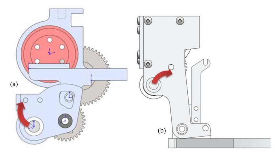
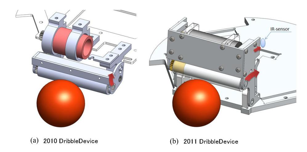
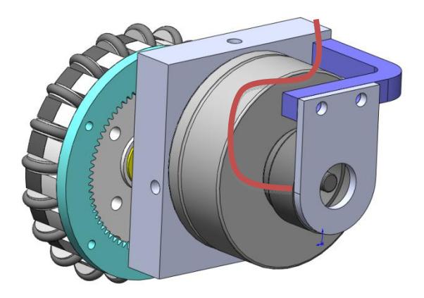
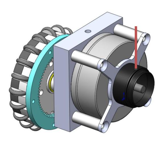
Figure 1 (a) and (b) shows the side view of dribbling device of 2010 and 2011 model, respectively. In similar, bird-view of that one is shown in Fig. 2. In 2010 model, it was used REmax24-motor as the dribble device motor. It was not optimal choice because of the requirement of that large space for diameter. In addition, the power of the dribbling motor (Maxon RE-max24) was not enough to give rise to the strong backspin of the ball for the back pass. So we change it to ECmax22-motor.
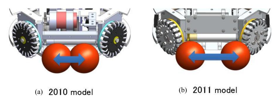
This motor has enough power to get strong back-spin. And the size is smaller compared with REmax24-motor. We also changed rotational orbit of the roller itself such as arrow shown in Fig. 1 (b) 2011 model. As the results, the quantity of horizontal-motion increased and it was worked better for role of the buffer material to catch a ball. Moreover, the dribble device would be able to keep in upper of the ball and in wide range of dribble bar, as the results of improvement of the height of chipkick bar and the position of IR sensor as shown in Fig. 3 and Fig. 2(b) (see in detail §3.3). The gear would not be also broken by improvement of the shock-absorbing mechanism.
The difference of the dribble device's performance is summarized in Table 2.
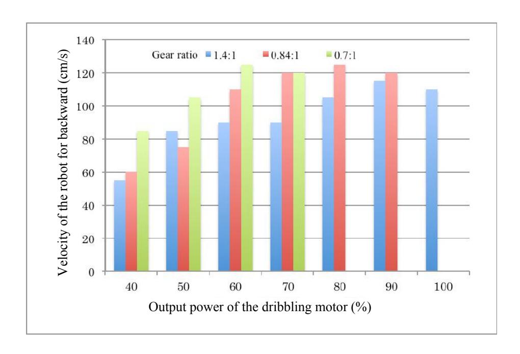
To decide the optimum gear ratio for the dribbling device, we measured the fastest backward velocity of the robot which was possible to keep holding a ball with the parameter of the output power of motor and the gear ratio.
Figure 4 shows the experimental results. It assumed 0m/s in Fig. 4, when the overload at the motor was occurred on the experimental condition. For the vertical axis, it shows the maximum velocity of the robot which could hold the ball. As shown in Fig. 4, the robot can move faster for backward on the condition of 70% output power with the gear ratio of 0.84:1 and 0.7:1 than that of 1.4:1. Moreover, the outputpower range of 0.84:1 is wider than that of 0.7:1. That is, the overload is occurred over 70% output-power in the case of 0.7:1. Thus, we decide the gear ratio to 0.84:1. And we confirmed that the backspin chip-kick was able to achieve in this condition.
Comparison between new and previous dribble devices' characterization
| New(2011) | Previous(2010) | |
|---|---|---|
| Dribbling motor | Maxon EC-max22 | Maxon RE-max24 |
| Power | 25Watt | 11Watt |
| Nominal speed | 9820rpm | 5870rpm |
| Nominal torque | 22.9mNm | 12.4mNm |
| Gear ratio | 0.84:1 | 1.31:1 |
Improvements in tire unit
A tire unit in 2010 is shown in Fig. 5. In EC45flat, we cannot fix directly the encoder to the motor. So, it was necessary to bend the encoder cable to assemble the robot in the case of structure shown in Fig. 5. The encoder is only fixed by adhesive tape. Thus, when the encoder cable was pulled by someone or somewhat accidents, the encoder was often come off. Therefore, we needed to change the configuration of the encoder. The 2011 model is shown in Fig. 6. In this structure, since the cable may not be pulled, the probability of coming off for the encoder will be lower. Moreover, we can treat easily for overhaul and use more flexible cable. In addition, this unit is constructed with the popular spacer that will be getting easily. Thus, it is very good to using for maintenance.
Change of the position of sensor to find a ball
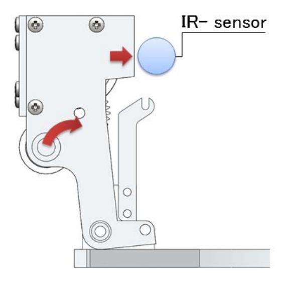
The sensor to find a ball for 2010 model was located in side of dribble device. Thus, when the sensor was damaged by a strong impact such as collisions between robots, the result caused trouble of mechanics and electrical circuits. So, we tried to change the position to of a sensor to find a ball. As shown in Fig. 7, we set the sensor to the position of back for dribble device. That is, the robot will recognize a ball indirectly through the detection of motion of the dribble device.
As the result, the motion-range of the dribble device would be wider. Because of the infrared sensor could be set up inside of the robot, the possibility of the breakdown would be lower. Moreover, the catching-range of the dribble device would be greatly wide.
Electrical design of new circuit
The new electronic circuits in 2011 model consist of two main boards. They are main control unit and peripheral control unit shown in Fig. 8, respectively. The main control unit includes the main CPU, power supply circuit, wireless communication module, ball detecting circuit and dribbling motor controller. The peripheral control unit includes BLDC controller and voltage booster.
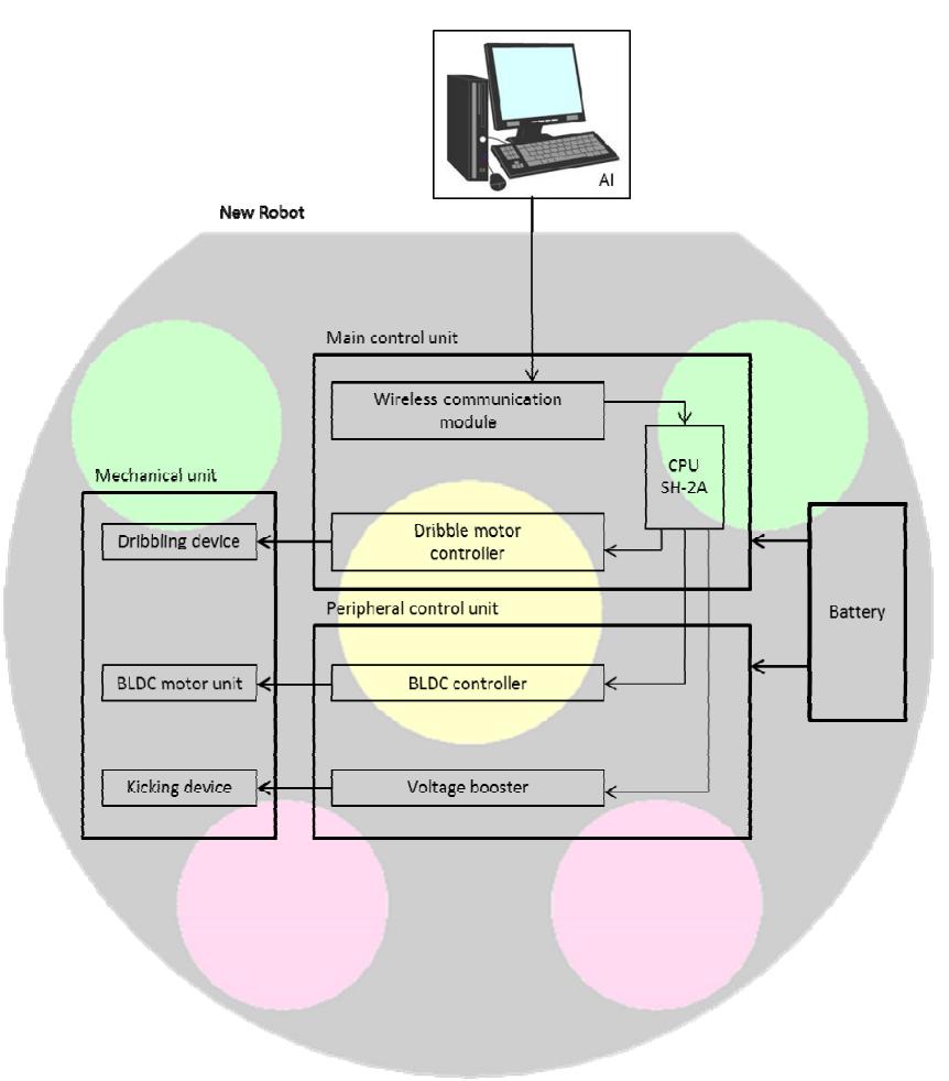
Main Control unit
We have developed new main control unit. This unit includes the circuit for detecting a ball, power supply circuit and wireless communication module. The SH7262 (SH-2A series of Renesas) is used for a main CPU that communicate each PIC to the peripheral controllers, such as BLDC controller, voltage booster circuit etc. The CPU runs 144MHz (345MIPS) and has 1MB RAM. Its performance is enough to achieve the precise control of the robot.
Wireless communication system
We have used the Digi's XBee module for communication system between host PC and each robot. The wireless communication frequency is 2.4GHz band. The XBee module is able to communicate faster than conventional wireless module. It is possible to communicate up to 115200bps. Up to now, the communication speed was 19200bps. So since we will be able to send more information to the robot, it is possible to develop more advanced controller.
BLDC controller circuit
An each robot has four BLDC control circuits for omnidirectional mobile. The MCU of BLDC controller is dsPIC30F4012. Three phase PWM module and Quadrature Encoder Interface for motor control in MCU are very useful for development of BLDC controller. The motor speed of the robot is controlled by PI speed control in MCU. This circuit is also used for dribbling motor controller.
Voltage booster circuit
The DC-DC converter to boost up the voltage is used for the solenoid. The input voltage of 16V is converted to 200V output. This chopper circuit is controlled by PIC in each robot. In the kicking device, the output voltage of 200V is charged in 4100uF capacitor. The time to charge up to 200V from 16V is 5 seconds.
Improvement of strategy system
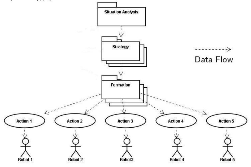
Strategy system was also improved. The architecture of new strategy system is illustrated in Fig. 9. The strategy system consists of four modules called "Situation Analysis", "Strategy", "Formation" and "Action".
Situation Analysis module
This module is located at top level in strategy system. This module plays the role of analysis about the game situation from both position of the ball and robots on the field, and generation of the trial instruction command.
Strategy module
This module is located at below level of Situation Analysis module. The role of this module is to select the optimal next Formation module from result of analyzing. For example, when the result of analysis is "Indirect Free Kick of Own team", the Strategy module will select the "Indirect Kick Formation module". On the other hand, when the result of analysis is "Need to Defense", the Strategy module will select the "Defense Formation module". Since the Strategy module has many strategy patterns, it will be able to select the optimal Strategy module corresponding to the game situation.
Formation module
This module is located at below level of Strategy module. This module plays the role of the decision of the next Action module which should be performed by each robot.
Action module
This module is located at the bottom level in strategy system. The role of this module is to command the specific operations to each robot. The "Direct Shoot Action" for instance, is command to kick a ball for the robot. Alternatively, the "Wall Defense Action" means moving the robot to the position to defend the goal.
Conclusions
We have improved the robots of SSL as well as last year. As the results, some problems found in last year were solved and the performance of the robot was achieved best among the recent years.
We hope that our robot will be doing the best in coming world competition. And we are happy, if the information mentioned above is somewhat useful for other team.
References
[1] Piyamate et al. Skuba 2010 Extended Team Description. In: Proceedings of RoboCup 2010.