KN2C Small Size Team Description Paper
Milad AbaeiRad, Majid Ahady, Salar Moghimi, Faraz Fallahi, Sina Sharafzade, Farzad Abedini, Kiyarash Afrasiabi, Mohammad Reza Saber, Soheil Kianzad
K.N.Toosi University of technology
Abstract This is a paper about KN2C Small Size Soccer Team*. In this paper you will read the main characteristics of this team in three parts. These parts are mechanics, electronics and software.
Team Members
Milad AbaeiRad, Majid Ahady, Salar Moghimi, Faraz Fallahi, Sina Sharafzade, Farzad Abedini, Kiyarash Afrasiabi, Mohammad Reza Saber, Soheil Kianzad
1 Introduction
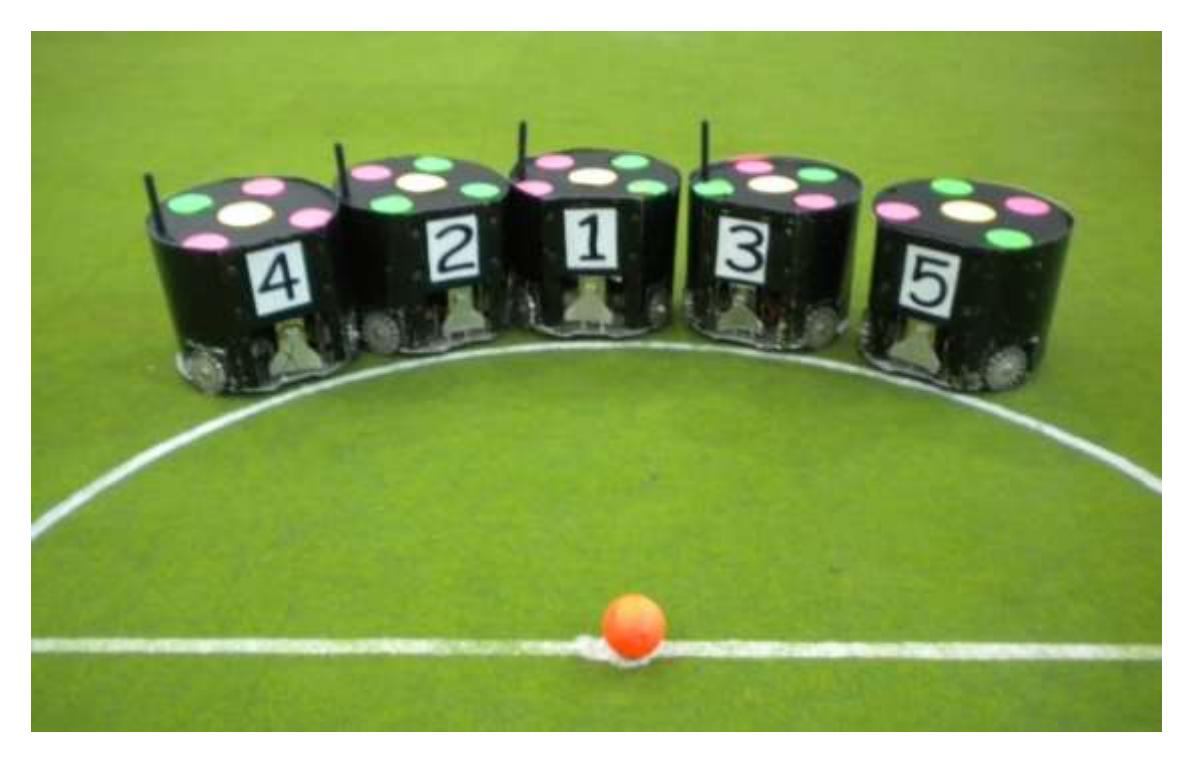
KN2C team has started its activities since November of 2009. The members of this team were student who has just entered the university and had interest and experience in robotic field. They arranged their new team in purpose of learning and participated in main related competitions since then. The first competition was Iran Open 2010. In this competition kn2c team got the forth place. After that, this team was conditionally qualified in world cup of 2010 but some matters occurred and the team didn't participate in that competition. The last one was AUTCUP 2010 which was held in Iran. We are looking forward to participate in Iran Open 2011 too.
2 Mechanics
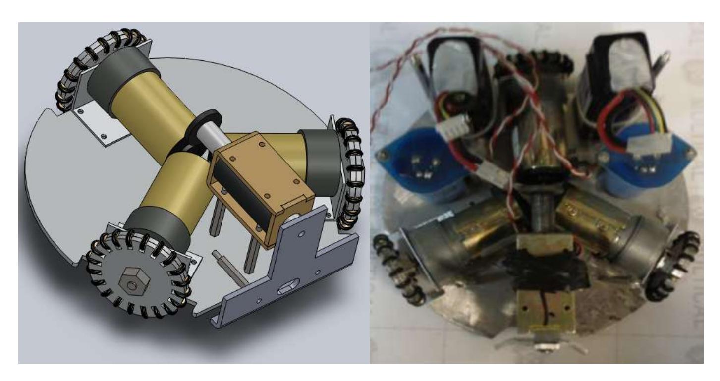
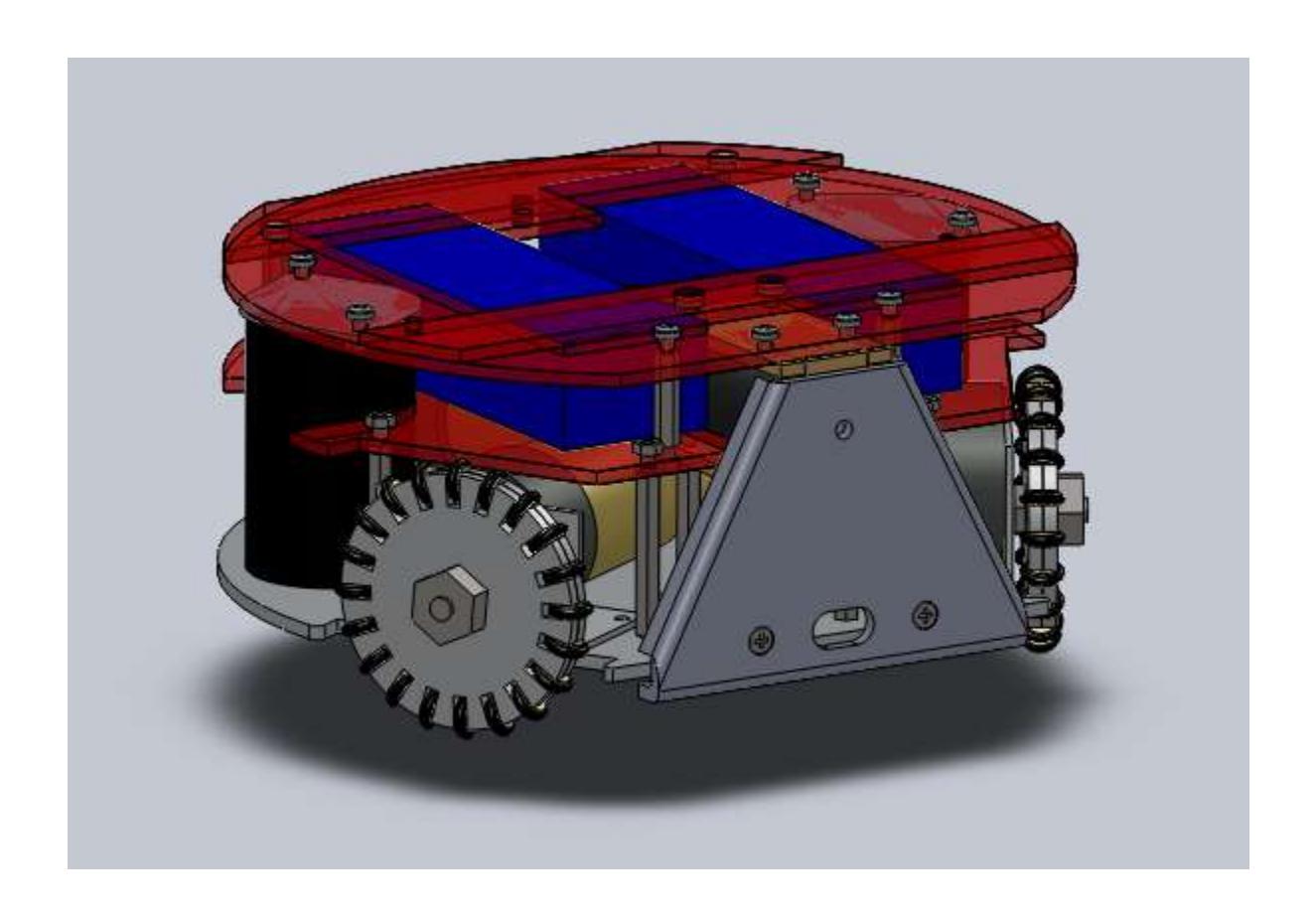
Robots are made in three surfaces. In first one motors, solenoid, batteries, kicking board and its capacitors are placed. These parts are symmetrically arranged to bring the center of mass to center of the surface. This makes undesirable torque equal to zero.
In second surface main electrical board is placed. And on top of third surface image processing's markers are placed.
2.1 Dynamic System
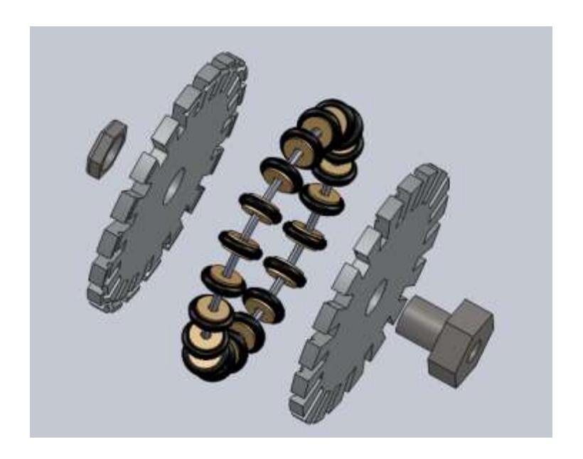
Speed of motors with gear boxes is 500 RPM. Power supply of motors is 24 V and gear boxes are 9.9/1. Angle between each pair of motors is 120˚ because this type of placing motors allows robots to move in all directions of X-Y surface and turn in direction of Z Axis. Because of this wheels are omni directional.
3 Electronics
Electronics section
3.1 Microcontroller
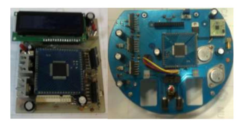
The main processor of the board is ATXMega64A3, which belongs to XMega family. XMega is the name of new family of AVR microcontrollers which is produced by Atmel Company since 2008. These microcontrollers work in a better performance. and lots of new characteristics makes them available to even compete with ARM microcontrollers.
Because this microcontroller has overcame the problems of previous ones and has lots of sidelong blocks like PWM generators in a wide range, KN2C team decided to use this one instead of ATMega16 which was used in previous competitions.
The route of electronic part is this: Microcontroller receives data from wireless module with Usart protocol. And send commands for motor derivers and kicking board. Microcontroller is responsible for some other duties like controlling charges of batteries and feedbacks.
3.2 Wireless communication
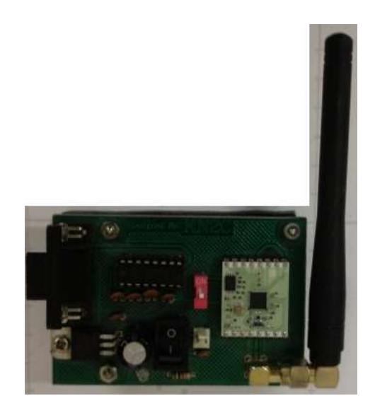
MULTICHANNEL RADIO TRANSCEIVER RXQ2-XXX GFSK modules are used to connect computer to robots via radio waves. These modules are available in frequencies of 433Hz and 868Hz. So it can be changed in competitions which the opponent has same frequency.
3.3 Motor's deriver
Each motor is operated with a full H-bridge driver named L6203. And speed of motors can be controlled with PWM pulse of microcontroller. (Due to connecting enable pin of L6203 to microcontroller)
3.4 Kicking
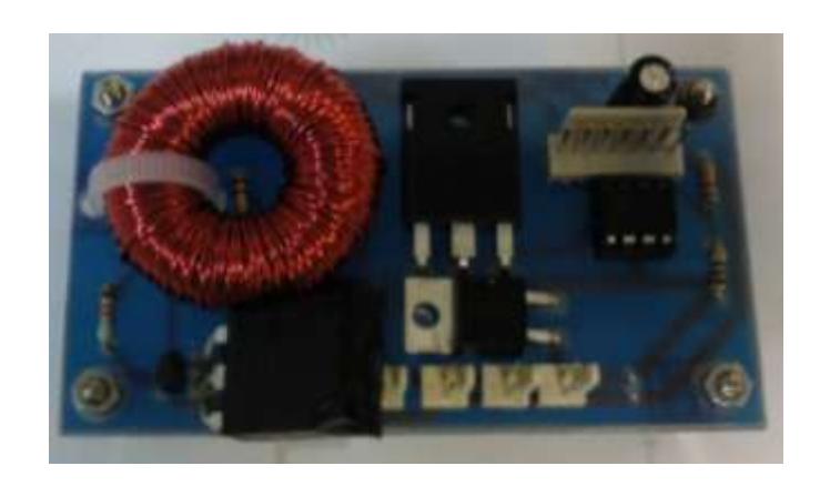
Each robot has a direct kicking system and a boost convertor circuit is used for kicking. With connecting and disconnecting voltage across the inductor, voltage increases. (It's possible because of electrical property of inductors). In this case 24V is converted to 200V. And it is stored in capacitors. Two 2200µF capacitors are used in each robot. In time of kicking energy of capacitors will be vacated in solenoid and it will kick the ball directly.
Here the method of storing high voltage in capacitors is simply explained: Current of inductor is connected and disconnected frequently by a MOSFET. This makes the output voltage go's up for an epsilon of time. This output voltage is connected to the positive side of a diode which makes a positive pick detector circuit with capacitors. So after each cycle the voltage of capacitors increases a bit. After a while this action is repeated for many times so the voltage reaches the amount of 200.
When ball becomes in front of a robot the software recognizes this event and informs that robot .But for more accuracy an IR transmitter with an IR sensor is placed on each robot to find the best position for kicking.
In time of kicking the energy of capacitors goes into the solenoid and sends shaft of solenoid forward. This shaft hits the ball and makes a kick.
4. Software
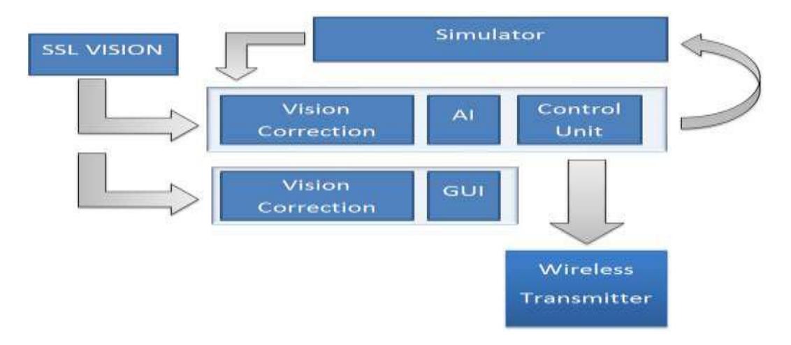
Software includes the following parts:
4.1 SSL-Vision
SSL-Vision is an open source program which is written for image processing. Due to rules declared by SSL organizing committee, using this program is mandatory for all of teams since 2010.
This program run's in Ubuntu 8.04 and after receiving video from cameras and processing it; SSL-Vision determines angles and coordinates of robots, coordinates of ball and confidences. Then this data will be sent to other computers.
4.2 Vision Correction
Vision Correction is related to receiving data from ssl-vision and correcting them. This part receives data packs from Google Protobuf and corrects them. For instance this part declares the right coordinates of the ball, Merges frames of cameras and recoups absence of robots in some of the frames. Finally corrected data will be sent to other parts of the software.
4.3 AI
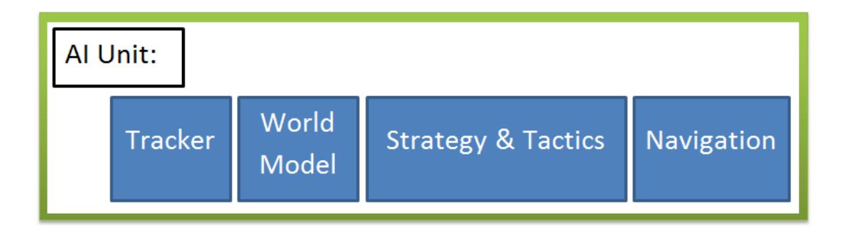
This part receives data of vision and referee box and makes main decisions of artificial intelligence.
4.4 GUI
GUI displays data of robots graphically. This part can be in different forms like: current position of robots, duties of robots and other tactics.
4.5 Controller
There is a movement vector and maximum speed for each robot. Controller block converts this data to speed of motors and makes data available to be used by robots.
4.6 Simulator
Output of controller block comes to this part to be tested in virtual environment. Output of this part can be used by vision correction part.
4.7 Wireless Transmitter
This part makes a connection between robots and computer and is in touch with main program with UDP packets. This part is connected to wireless module by serial port.
4.8 Micro Controller
Codes of micro controller are written in CodeVisionAVR V2.05.0 Advanced. This software is the latest version of CodeVisionAVR and supports XMega family.