NUST Falcons - Team Description for RoboCup Small Size League, 2011
Arsalan Akhter, Muhammad Jibran Mehfooz Awan, Ali Imran, Salman Shafqat, M. Aneeq-uz-Zaman, Imtiaz Noor, Kanwar Faraz, Shoab A Khan, Khalid Munawwar
College of Electrical and Mechanical Engineering, National University of Science and Technology, Pakistan
Abstract This Team Description Paper describes an overview of the team NUST FALCONS for the Robocup Small Size Robot League 2011. This paper gives an overview of the current status and the progress of the system developed so far.
1. Introduction
NUST Falcons is a team in its inception phase at National University of Sciences and Technology, Pakistan. Since Robocup provides an exciting yet challenging platform of research, the team started its work about a year ago, geared towards participation in Robocup Small Size League. As a starting point, differential drive robots were employed in order to develop basic infrastructure. The main focus was on building reliable image processing and motion planning techniques. This year, the paradigm was shifted more towards the hardware and mechanical design of the robots, so that a platform compatible with the current requirements of Robocup may be developed. Inclusion of omni-drive system, getting the SSL vision system ready and inclusion of wireless modules are the major achievements made so far.
2. Development of our own Vision System
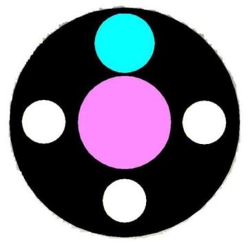
As constrained by a cheap web cam, it was difficult to achieve a reliable accuracy with the color markers used as standard in Robocup, since we had to face the issues of bad color response, less no of pixels and color-bleeding. To get the system up and running, we developed our own color marker scheme, as shown below.
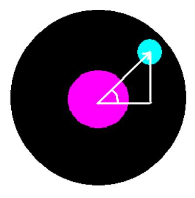
In this marker scheme the central magenta blob was used to find the coordinates of the robot. The cyan blob was used to find the orientation of the robot. The smaller white blobs were used to find the id of the robot. For example in this case there are three white blobs, so this is robot number three. This approach provided better color approximation, fully satisfying our needs. The blob detection was done by color-based image segmentation in the RGB planes. Then coordinates of the blobs were calculated by performing a blob analysis on the Regions of Interest (ROI) cropped from the image. The angle of the robot was calculated by employing basic trigonometric functions on the co-ordinates of the magenta blob and cyan blob.
The algorithms were first implemented in MATLAB and later in OpenCV. Manual calibration was a big limitation as OpenCV requires a range of RGB values specified by the user, which have to be given one by one, making the process tedious.
3. Overview of the Control System
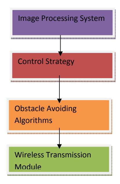
An overview of the entire control system is illustrated below
With the help of coordinates of the robots, their orientations and the ball's coordinates given by the vision system, Control Strategy determines the best way for the robot soccer team to react. It uses AI in the task, to manipulate a complete strategy for the team that optimizes the results.
Information gained from control strategy is then conveyed to the robot with the help of wireless transmission module. A special format is used in the transmission to filter out any garbage data caused by RF noise. The robot receives this data and changes its velocities accordingly.
4. Obstacle Avoidance Algorithms
The Obstacle Avoiding Algorithm takes in the coordinates of the robots and then calculates a trajectory for each robot that will get it to its final destination without hitting any other robots. The algorithm does this for every robot in the team one-by-one. The trajectory calculated is in the form of translational and rotational speeds of the robot. Obstacle avoidance refers to the methodologies of shaping the robot's path to overcome unexpected obstacles. The resulting motion depends on the robot actual location and on the sensor readings.
The algorithm chosen for the task of Obstacle Avoidance is Velocity Obstacle. It takes into account the velocities of the obstacles, destination and the robot as well as their coordinates and considers the velocities of the obstacle before planning. It is computationally a cheap algorithm.
A huge drawback of this algorithm is that the instantaneous velocities of the robot and the obstacles have to be known accurately. Otherwise the algorithm can produce largely erroneous value. Since the vision system is prone to a lot of electrical noise, fluctuations are caused in the values of coordinates of robots. When velocities are calculated these fluctuations are amplified and cause disruptions for the algorithm. This problem can be fixed by applying filtering on the output of camera, and we hope to achieve this in the future.
5. Control Strategy
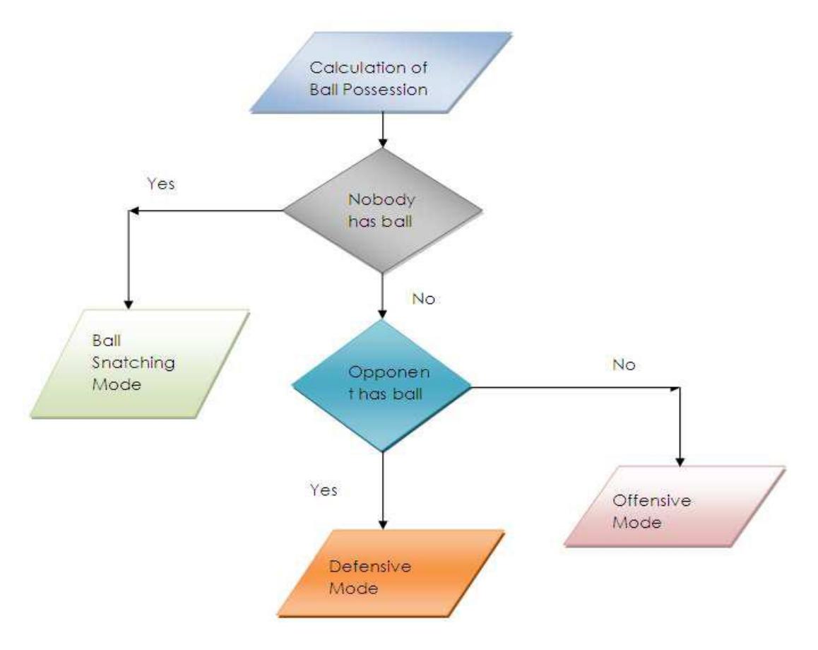
Strategies used by the robots exist in at two different levels. At first level processes are there to command the robots. At second level, robot processes relies on robot precision to carry out the task given by the main system, which is executed by the controller used to manipulate the commands given by the main system. These commands generated by the system which includes vision system, algorithms for obstacle avoidance and motion planning. Following is the flow diagram which gives the overview of control strategy.
A reflex based strategy has been employed. It selects from defensive, offensive or ball snatching mode. Depending on the mode selected, it orients itself towards the target, or do obstacle avoidance.
6. Hardware Description(1st Generation)
The robots employed for the implementation of above strategy consisted of differential drive. The main features of the robots are as under.
6.1 Micro-controller
The Micro-controller used is Atmega8L from ATMEL. The ATmega8 is a low-power CMOS 8-bit microcontroller based on the AVR RISC architecture. It was selected due to its powerful features, low cost and less space.
6.2 Wireless Receiver Module
The wireless module used is RF Link 2400bps, 315MHz Receiver from Sparkfun Technology. Multiple 315MHz receivers can listen to one 315MHz transmitter.
6.3 The Motors
The motors are geared with a voltage rating of 6 VDC and a current rating of 380mA.
6.4 Sensors
Two main types of sensors are used on the robot
Bump sensors
Infrared sensors
These sensors were employed to assist in Obstacle Avoidance.
6.5 Batteries
NiMH batteries were used to power up the robot
6.6 Ball Holders
Custom ball holders were employed so that the robot could dribble the ball.
7. 2nd Generation of robots
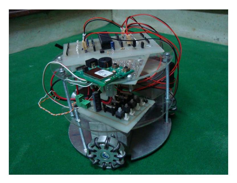
Since the robots employed in the first generation were bulky and constrained with differential drive, it was decided to build new robots which could meet the current requirements of Robocup Small-Size League.
7.1 Mechanical Design
(no intro text)
7.1.1 Dimensions
The robot fits within a cylinder of diameter 180mm. The height of the robot is a bit more than 150mm which will be corrected in coming days.
7.1.2 Base Plate and Chassis
The Base plate consists of a sheet of aluminum with a thickness of 3mm. Cuts are present at the places where wheels are attached. The design of the chassis was inspired from the design of team KN2C[1].
7.1.3 Wheels
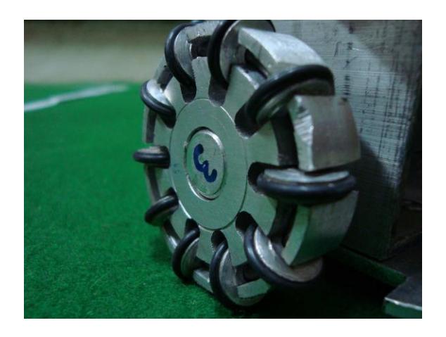
The wheels of the robot consist of 10 rollers on the rim. Instead of conventional two-plate design, only a single plate was used in which the rollers were locked in the grove using a hard metal wire.
7.1.4 Motors
Geared, brushed DC motors were employed having a good rpm in order to drive the robot. We had to use three motors due to lack of space. We plan to use better motors in future.
7.2 Electronics
(no intro text)
7.2.1 Microcontroller
Atmel AVR ATmega16 is being used as the brain of the robot. The micro-controller is responsible for sending commands to the robot and also communication with the main computer.
7.2.2 Wireless Module
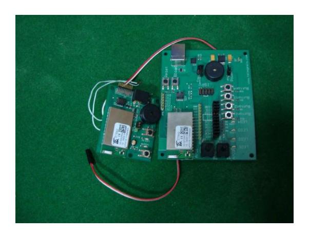
ETRX2 Wireless module from Telegesis is employed in the robot. The module communicates with the main computer at a frequency of 2.4GHz, using AT commands.
7.2.3 Kicker
We plan to use a solenoid based kicker for kicking mechanism.
Conclusion
Although fun in spirit and exciting to watch, the true purpose of Robocup is to present state-of-the-art research in artificial intelligence and to highlight the potential of collaborative robot teams. We hope to contribute to the initiative in a healthy way by playing our part. We look forward to play our part to the initiative in coming future.
References
- KN2C 2010 Team description paper, Robocup Small Size League.