ODENS 2011 Team Description
Yoshihiro Fukumoto, Makoto Nakajima, Yasuhiro Masutani
Osaka Electro-Communication University 1130-70, Kiyotaki, Shijonawate, Osaka 575-0063, Japan
Abstract In this paper, the system of team ODENS, Osaka Electro-Communication University, Japan is introduced. Although the hardware of robot is designed and manufactured by a company, the software of controlling 4-wheeled omnidirectional mechanism is original and is described in detail. The system outside of the field consists of a server PC and some client PCs. The server converts information from SSL-Vision and referee box and sends them to the clients. It also collects commands from the clients and sends them to the robots by wireless. The clients decides action of corresponding robots one by one based on the information received from the server. The method of predicting the robot position is newly introduced.
1 Introduction
Team ODENS consists of members of Masutani Laboratory in Department of Computer Science, Faculty of Information Science and Arts, Osaka Electro-Communication University, Japan. ODENS has participated in RoboCup competition since RoboCup Japan Open 2007. The results in the Japanese competitions of ODENS were the 4th place in 2007, the 2nd place in 2008, the 3rd place in 2009, and the 2nd place in 2010. Moreover, they were the 4th place in RoboCup 2009 Graz[1] and in the twelve best teams in RoboCup 2010 Singapore[2].
In the Department of Computer Science, "Exercise in Robot Programming" is organized for the second grade students, which uses the actual robot system for RoboCup competition. Students learn basic programming of deciding action of soccer robots in the exercise. In the room for the exercise, full-size SSL field and two ceiling cameras are readied. Since ODENS develops robots and programs there, it can always do exercises and experiments on the assumption of regular game.
In this department, students belong to laboratories from the second semester of the second grade. Students who are interested in soccer robot through "Exercise in Robot Programming" wish to enter Masutani Laboratory. In Masutani Laboratory, projects for RoboCup are themes for pre-seminar before regular graduation thesis. Moreover some students study RoboCup as also theme of graduation thesis.
Since the department is in the field of computer science and technology, the second grade students focus on development of software for deciding action. The hardware of robot is designed and manufactured by a company. The software of controlling omnidirectional mechanism is improved by graduate students and higher grade students.
In the following sections, the hardware and software of robot is introduced first. After that the computer system outside of field, especially a method of deciding action and a future prediction are described.
2 Overview of the system
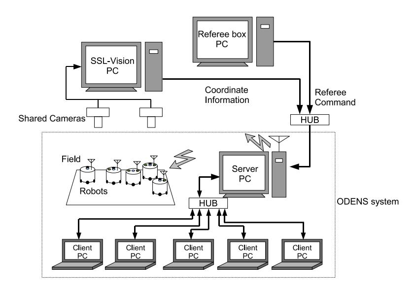
The system of ODENS is a distributed and autonomous system, which consists of one server and some clients as shown in Fig.1. One client program corresponds to one robot. All client is independent of each other. The server receives coordinate information of objects in the field provided by SSL-Vision. They are transformed in appropriate format and sent to the clients. Signals from the referee box are also sent to them. Each client program decides the next action for the corresponding robot based on the information received from the server and sends a command back to the server. The server collects the commands from all clients and sends them to the robots in the field by wireless. The above cycle is executed 60 times in one second.
3 Robots
The mechanical and electrical hardwares of robots is designed and manufactured by SMATS Corp., which is very similar to RoboDragons 2009's robot[3]. However, the onboard software for control is original.
3.1 Hardware
An appearance of the robot is shown in Fig.2. The main specification is shown in Table 1.
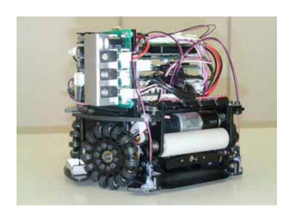
Table 1. Specification of the robot
| Dimension | length 179[mm], width 179[mm], height 140[mm] |
|---|---|
| Mass | 2.2[kg] |
| Wheel | number 4, radius 30.5[mm], sub wheels 15 |
| Motor | maxon RE-max23 222050, 11[W], reduction ratio 7.916 |
| Kicking device | 3 solenoids, 240[V] |
| Dribbling device radius 10[mm], length 72[mm] | |
| Ball sensor | LED and Phototransistor, number 4 |
| Gyro sensor | ADXRS610 |
| Wireless modem | Futaba FRH-SD07T, 2.4[GHz] |
| CPU | Renesas $SH7045F(SH-2)$ |
| Battery | Li-Polymer $14.8[V] \times 1$, $7.4[V] \times 1$ |
3.2 Software for Robot Control
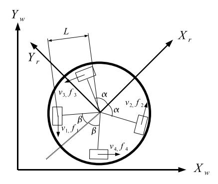
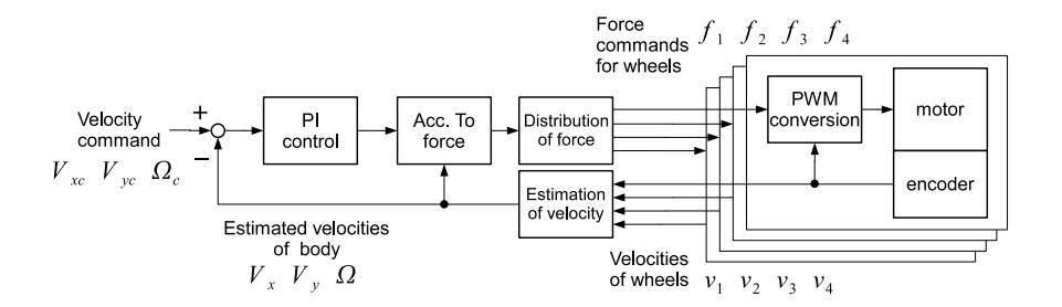
The program of CPU on the robot is developed with GNU C compiler. Three tasks are concurrently processed on the CPU. Task for feedback control is executed every 2[ms]. Task for communication receives a command from the outside via wireless modem every 16.7[ms]. The command consists of magnitude and direction of linear velocity, angular velocity, and on/off of dribbling device and kicking device.
4 Server
PC The server PC is equipped with Intel Core2 Duo P8700 2.53[GHz] and 2[GB] RAM. It is connected to the SSL-Vision PCs, referee box PCs, and some client PCs through LAN. It also uses a USB-serial converter to connect the wireless modem.
Wireless communication Wireless modem Futaba Corp. FRH-SD3T is used to communicate with the robots in the field, whose communication rate is 38.4[kbps] and whose frequency is 2.4[GHz].
4.1 Hardware
PC The server PC is equipped with Intel Core2 Duo P8700 2.53[GHz] and 2[GB] RAM. It is connected to the SSL-Vision PCs, referee box PCs, and some client PCs through LAN. It also uses a USB-serial converter to connect the wireless modem.
Wireless communication Wireless modem Futaba Corp. FRH-SD3T is used to communicate with the robots in the field, whose communication rate is 38.4[kbps] and whose frequency is 2.4[GHz].
4.2 Software
OS for server PC is Microsoft Windows XP Professional SP3. Visual Studio 2008 C++ is used to develop the program. The server program has GUI and consists of multiple threads. These threads have functions respectively as follows.
S-V Watcher SSL-Vision Watcher is a thread to merge and manage the field informations divided into two that is given from SSL-Vision. It gives the merged field information to the "Position estimation" thread mentioned later.
Threads
Kalman Filter thread The positions and velocities of objects are estimated by Kalman filter, whose observed values are the position of the objects given from S-V Watcher and whose model is a constant velocity motion. Furthermore, this function tackles exceptional situations by evaluating the difference between the observed value and the estimated value. It gives the estimated information such as robot number and coordinate to the network thread.
Network thread The network thread transmits the information received from the Kalman filter thread and the signals from the referee box to the client(s). Moreover this thread to accepts the connection request from the client(s).
Referee thread The referee thread transforms the signals received from the referee box to the network thread.
Recieve thread The receiver thread communicates with the client(s). However, this thread does not transmit the message to the client(s). It receives the command to the robot from the client(s). Since this thread corresponds to a client, the number of the threads increases and decreases depending on the number of the connected clients. It gives data which received form the client(s) to the radio thread.
Radio thread The referee thread transforms the signals received from the referee box to the network thread.
GUI thread The GUI thread accepts the input from the user and performs indication to the display. The processing priority of this thread is lower than other threads not to obstruct the more important threads.
5 Client System
PC executing the client program does not need special specification and performance, whose OS is not specified (We use both Windows and Linux). Only function of network communication is needed to connect to the server.
5.1 Hardware
PC executing the client program does not need special specification and performance, whose OS is not specified (We use both Windows and Linux). Only function of network communication is needed to connect to the server.
5.2 Software
Structure of action decision One client program corresponds to the one robot. Therefore, all clients program are executed independently of each other. The structure of client program is separated into four layers in Game layer, Role layer, Task layer and Communication layer.
Game layer This layer is processed based on a state transition, whose state is switched mainly by command received from the referee box. There are five states, "Out of play", "Pre set play", "Set play", "In play", and "Halt".
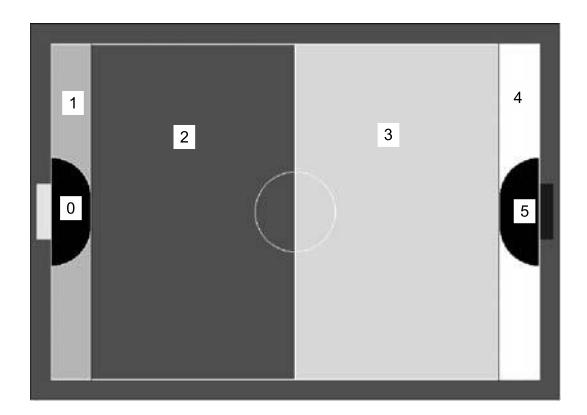
Table 2. Role table
| Column 1 | Column 2 | Column 3 |
|---|---|---|
| BG BG BG BG AT1 | BG BG BG BG BG | both teams are near |
| AT1 AT1 AT1 AT1 AT1 AT1 | AT1 AT1 AT1 AT1 AT1 | BG BG BG BG BG |
| AT1 AT1 AT1 AT1 AT1 | AT1 AT1 AT1 AT1 AT1 | AT1 AT1 AT1 AT1 AT1 |
| BG BG BG BG AT1 | BG BG BG BG BG | BG BG BG BG BG |
| BG BG BG BG AT1 | BG BG BG BG BG | GD GD AT2 AT2 AT2 AT2 |
| CD PC AT2 AT2 AT2 AT2 | ||
| GD GD AT2 AT2 AT2 AT2 | ||
| GD GD GD AT2 AT2 AT2 | ||
| GD GD GD AT2 AT2 AT2 | ||
| GD GD GD GD PW2 PC | ||
| GD GD GD GD PW2 PC | ||
| GD GD GD GD PW2 PC | ||
| GD GD GD GD PW2 PC | ||
| PW2 GD GD GD GD | ||
| PW2 GD GD GD GD | ||
| PW2 PW1 PW2 GD GD GD | ||
| PW2 PW1 PW2 GD GD GD | ||
| PW2 GD GD GD GD | ||
| PW2 GD GD GD GD | ||
| PW2 PW2 GD GD GD | PW2 PW2 PW2 GD GD GD | PW2 PW2 PW2 GD GD GD |
| PW2 PW2 GD GD GD | PW2 PW2 PW2 GD GD GD | PW2 PW2 PW2 GD GD GD |
| PW1: PassWaiter1 | ||
| PW2: PassWaiter2 |
Communication layer This layer has functions for communication.
6 Future Prediction
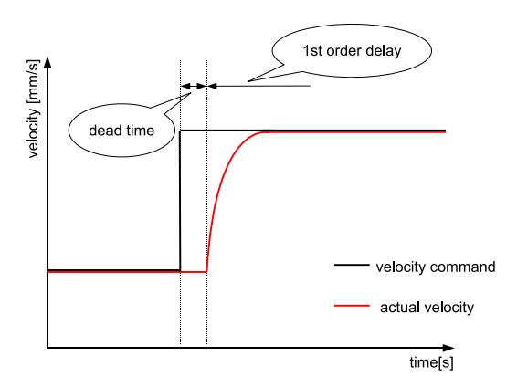
The ODENS system has dead time and delay between the time when the program sends velocity command to the robot and the time when the program receives the information of the robot position as shown in Fig. 6. Due to this characteristics, the positioning control was not good in case of high speed. To overcome the problem, ODENS 2011 introduces a future prediction based on the past commend sequence.
Let $T_d[s]$ be the dead time in the whole system. The delay is modeled as 1st order delay whose time constant is $T_{1*}[s](* \text{ is } v \text{ for linear velocity}, w \text{ for angular velocity})$. Let $t_s[s]$ denote the control period. Let $v_n$, $\phi_n$, and $\omega_n$ denote the magnitude of linear velocity command, the direction of linear velocity command, and angular velocity command respectively. The estimations of components of delayed velocity $\overline{v}{xn}$, $\overline{v}{yn}$, and $\overline{\omega}_n$ are computed as follows.
$$\overline{v}{x0} = v{xb} \tag{15}$$
$$\overline{v}{xn} = (1 - a_v)\overline{v}{xn-1} + a_v v_n \cos(\theta_n + \phi_n) \tag{16}$$
$$\overline{v}{y0} = v{yb} \tag{17}$$
$$\overline{v}{yn} = (1 - a_v)\overline{v}{yn-1} + a_v v_n \sin(\theta_n + \phi_n) \tag{18}$$
$$\overline{\omega}_0 = \omega_b \tag{19}$$
$$\overline{\omega}n = \overline{\omega}{n-1}(1 - a_w) + a_w \omega_n \tag{20}$$
where $a_* = t_s/T_{1*}$, $n = 1, 2, \dots, n_d$, and $n_d = T_d/t_s$. Let x, y, and $\theta$ be x-, y-coordinates and direction of the robot provided by the server respectively. The predicted coordinates $x_p, y_p$, and $\theta_p$ are computed as follows.
$$x_0 = x \tag{21}$$
$$x_{n+1} = x_n + \overline{v}_{xn} t_s \tag{22}$$
$$x_p = x_{n_d} \tag{23}$$
$$y_0 = y \tag{24}$$
$$y_{n+1} = y_n + \overline{v}_{yn} t_s \tag{25}$$
$$y_p = y_{n_d} \tag{26}$$
$$\theta_0 = \theta \tag{27}$$
$$\theta_{n+1} = \theta_n + \overline{\omega}_n t_s \tag{28}$$
$$\theta_p = \theta_{n_d} \tag{29}$$
In the improved system, $x_p, y_p$, and $\theta_p$ are used instead of x, y, and $\theta$ respectively.
7 Conclusion
As mentioned above, the part of deciding action is perfectly separated from image processing and robot control in the system. Owing to this feature, this system became useful platforms for both education and research. For the purpose of education, many students learned robot programing by using it. On the other hand, ODENS won the 4th in the RoboCup 2009 Graz by using the same system.
Although under the SSL regulation it is possible to make centralized system, in the system of ODENS, the program for each robot is independent of others. In the future, following this policy we will study robot system and participate in competitions.
References
- [1] K. Kanaya et al., "ODENS 2009 Team Description", RoboCup2009 (2009).
- [2] M. Nakajima et al., "ODENS 2010 Team Description", RoboCup2010 (2010).