RFC Cambridge
Alexei Colin, Julie Henion, Rui Jin, Benjamin Johnson, Svilen Kanev, Lisa Liu, Aaron Rameriz, Marcel Thomas, David Wu
Massachusetts Institute of Technology, Cambridge, MA 02139, USA; Harvard University, Cambridge, MA 02138, USA
Abstract Most of the hardware and software is the same as previous years. In this paper, we describe the hardware and software changes should improve the robustness of our robots. Major changes included variable capacitor charging, a new breakbeam design, a new low level controller, and improvements to the AI.
1. Team Description
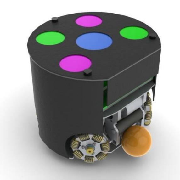
RFC Cambridge is a joint MIT-Harvard team in its sixth year of competition in Robocup. We participated in the international Robocup competition in 2006, 2007, and 2009, as well as the US Open in 2008, 2009, and 2010. The team consists of approximately fifteen members split working in four integrated subteams: mechanical, electrical, computer science, and controls. We are the only Harvard-MIT organization, one of few engineering clubs at Harvard, and one of the few completely undergraduate-led RoboCup teams. Our robot team consists of X INTEGETER of omni-directional wheels powered by a brushless motor system. Each robot has a rubber-coated dribbler and an electro-magnetic solenoid for planar kicking. The current height of the robot is 15cm; the maximum diameter of the Robots projection to the ground is 18cm; and the maximum percentage of ball coverage is approximately 19.
2. Hardware
2.1 Solutions to Known Problems
While last year we focused on the overall design of the robot for ease of access and assembly, this year we've decided to focus on performance of individual components. This fall, we focused on redesigning the kickers and wheels, and this spring we hope to implement new designs of the dribbler and shield.
2.2 Increase in Design Modularity
We have also taken to designing around a modular frame, rather than a fully integrated design. As an example, the wheel, the motor, and the shaft encoder are all mounted on a single rigid structure. When any component fails, the module can quickly be removed and replaced, allowing the robot to be returned to the playing field in a quick fashion. Further, each Drive-train module is built out of the same components, but is reconfigurable to be a left or right-handed component simply by altering the order in which it is assembled. This cuts down the number of components that must be designed, and speeds up manufacturing processes. The hope is that at the end of our design phase, we should be able to rapidly produce an ample team size without an unbearable time commitment to machining. A new potential update to this year's design includes reconfiguring the modules so that there isn't a "left" and "right" version. In an ideal situation at competition, if one module broke, you should be able to replace it really quickly with any spare, not worrying if it's the correct one.
2.3 Kicker
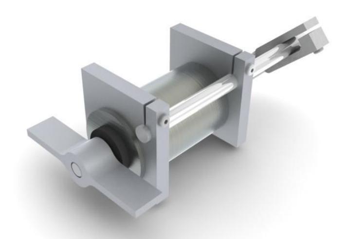
We identified that the primary issues in our old kicker design were robustness and repeatability. We have implemented a new kicker design that is properly constrained, and easier to assemble. There are some issues such as the tolerances that we have to hold on the press fit, but with reamers and proper machining practices, we were able to hold these tolerances. We also used a lighter spring, which exposed an electrical problem with the solenoid that was resolved.
2.4 Wheels
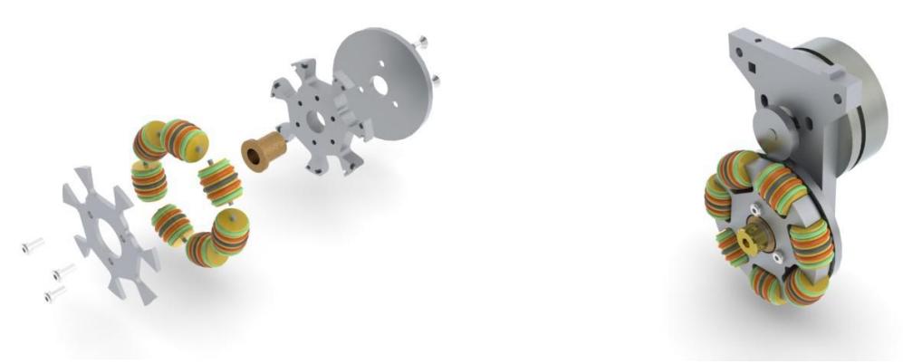
At the beginning of this year, we identified several large problems with the wheel design. The most important of these were related to inconsistencies in our machining processes leading to erratic wheel behavior, particularly wheel wobble and run-out. To eliminate the wheel wobble, the new design uses a 1/2" long graphite impregnated bronze bushing instead of using two ball bearings placed 1/4" apart. To address the problem of run-out, we used a CNC Mill instead of a Waterjet to manufacture the wheel bodies, since this improves concentricity of the center hole to the roller locations. Some smaller issues we've encountered in the past on the wheels include smoothness of driving and driving noise. To address these problems, we decided to experiment with a new wheel design this year which uses wider roller that are barrel shaped, following the outline of the wheel. These wide rollers decrease the robot's bumpiness on the field, and since there are few of them, that means fewer parts on the wheels making noise as the robot is running.
2.5 Shields
We have explored new methods of making the shields curved, namely by using the laser cutter to score lines in the ABS plastic and bend at the score lines to make an approximately curved shield. The advantage of this system is that it would give us more repeatable results and it is much easier to fabricate. The disadvantage is that it needs to be reinforced because it is inherently fragile.
Other possible ideas include clamping the unformed shields around the molds and then heating them up. The plastic will form to the shape of the mold. When removed and cooled, the shield will be exactly the shape of the mold. We also hope to attach these curved pieces to the shield tops using ABS welding, which we hope will be stronger in matches than the epoxy bonding we already use.
2.6 Dribbler
In Singapore, the dribbler was among the biggest problem assemblies we had. The pulley driving the dribble bar was improperly tensioned, so it couldn't rotate the ball. Also, the motor we were using took a very large amount of current, even at no load. Finally, the previous design was severely overconstrained, so if you tightened the dribbler all the way, the dribbler bar wouldn't always rotate.
We plan on addressing all these issues in our design which will be completed this spring. At the moment, we are looking at motor specs and creating a solid model which is focused on resolving all of the problems we've faced running our old dribblers.
3. Electrical
3.1 Consistency
One persistent problem on our robots has been erratic rotations (twitching) of the wheels on start-up of the robots. The problem is pervasive across all motors and robots. The start-up twitches cause current draw spikes through the brushless motor MOSFETs, often triggering overcurrent lockout conditions on the MOSFET driver. Additionally, people turning on the robots have faced a risk of getting their fingers pinched by the wheels.
The twitching is a consequence of changes to the PIC microcontroller firmware driving the brushless motors. The firmware was recently modified to include a new feedback control loop that provides stronger and more stable feedback. To locate the cause of the twitching, we replaced this control loop with a simple proportional controller. If the twitching had stopped and the motor functioned properly, the problem would have been in the controller logic. Instead, the new controller had problems of its own. While the wheels would not twitch on start-up with the new controller, the resistance provided by the motor to manually turning the wheels was not smooth, and the wheels rotated non-uniformly. Thus, we decided that the problem was elsewhere in the firmware. Since the twitching only occurred at start-up, we suspected that there was an error in an initialization value.
One error we found was in the firmware variable containing the duty cycle for the MOSFETs. The variable contained 12 bits of data in which only the upper 10 bits were used for the actual duty cycle. Eliminating the lower 2 bits did not seem to stop the twitching, however.
Another error we found was in the initialization value of the encoder value. This value was originally set at 0. At start-up, if the motor turned slightly to cause the encoder value to become more negative than its initial value, the value would wrap around to 0xFFFF. Since the feedback control loop uses differences in encoder values to calculate duty cycles, it would interpret this slight change in motor position as a seemingly large change and thus drive the motor very strongly to counteract this extreme difference in encoder values. To fix this problem, the initialization value should be set to about the middle of its range, such as 0x8000, so slight initial movements of the motor do not cause the variable to wrap around.
Fixing this issue noticeably reduced twitching, but did not eliminate it. We are currently investigating more causes for the twitching.
3.2 Solenoid Optimization
The kicker uses a plunger to hit the ball. The magnetic plunger is driven forward by a sudden discharge of current from two capacitors on the robot into a solenoid surrounding the plunger. Occasionally, the plunger shoots outward and sticks there. There are two consequences of this. First, the fact that there is still force driving the plunger forward after it has hit the ball implies that energy is not being efficiently delivered to the ball. Second, the robot is unable to kick the ball again until the plunger retracts. We believe the problem is that after the plunger has shot forward, the capacitors are still discharging into the solenoid. In other words, the time it takes for the capacitors to completely discharge is slow compared to the forward motion of the plunger. We intend to pick a solenoid with an inductance and resistance that will allow us to match the time constant of the plunger action with the time constant of the capacitor discharge. An optimized solenoid uses energy more efficiently, which will result in stronger kicks and prolonged battery life.
3.3 Variable Charging of Capacitors
The capability to kick the ball at different speeds is a desirable and very useful quality. It enables soft kicks for delicate passing and hard kicks for long-range shooting. There are two main ways of implementing this capability.
The first is to control the discharge of capacitors into the kicking solenoid. The hardware in the robot currently does not support this function. While there are two capacitors on each robot, they are connected to each other and thus discharged together. The discharging is controlled by SCRs, which only stop the flow of current into the kicking solenoid when the capacitors are completely discharged. Theoretically, variable kicking speeds implemented through controlling the discharge of capacitors is difficult to implement because of the large discharge currents and voltages (creating voltage spike issues in switching implementations) and the fast rate of discharge (limiting granularity of control).
The second solution is to control the charging of capacitors. We implement this in firmware. We redesigned the kicker controller board on the robot to include an op amp to measure the capacitor voltage. An integrated analog-to-digital converter in the PIC microcontroller on the kicker controller board measures this voltage. The microcontroller firmware cycles charging the capacitor to keep this measured voltage within a hysteresis range of the desired value. The variable charging controller works well and is generally able to keep the actual capacitor voltage to within 25 volts of the desired voltage.
3.4 New Break Beam Sensor
We are upgrading the break beam sensor and mounting it in a different location on the robot in order to allow a wider dribbler motor. This will allow the ball to be captured by the robot in a wider range. We will mount the new break beam sensor further back underneath the robot and to the side, so that it looks diagonally on the ball.
We cannot keep using the old break beam sensor for two reasons. First, the sensor is in two parts -- an IR LED and a receiver. Mounting it so it looks diagonally on the ball implies that there will no longer be a direct line of sight between the LED and the receiver. Instead, we would need to rely on the reflectivity of the ball for the light from the LED to reach the receiver. In our experiments we found that the ball was not reflective enough. Also, the aluminum plates forming the chassis of the robot are much more reflective than the ball, and that could cause noise in the received break beam signal.
A second disadvantage of the old sensor is its undesirable hysteresis. In our experiments, the break beam would not be broken according to a set threshold of received infrared light. Instead, the threshold relied more heavily on recent levels of and changes in received light. The effect of this was that the break beam, mounted in the new location, would not always be broken by the presence of a ball -- the output depended on factors such as how rapidly the ball entered the break beam path and the ambient light conditions.
The new break beam sensor includes an IR LED and receiver in one package. It is smaller than the old sensor and includes a simpler interface with a PIC microcontroller. Implementing this new break beam sensor is a work in progress, which we expect to complete by the international competition.
4. Software Improvements
4.1 Skills/Tactics/Plays architecture
During the last year, we adopted a Skills/Tactics/Plays (STP) [1] architecture for our AI system. In a nutshell, skills are single-robot, low-level primitives that only concern the robot itself (move, kick, dribble, etc.); tactics are game primitives that can describe the game-aware behavior of multiple robots (strike, defend point, goalkeep, etc.); plays are multi-robot game primitives that describe the synchronized behavior of a significant part of the robot team (two-person attack, two-person defense, etc.). In prior years, our play architecture consisted only of plays and skills, but increased playbook size and complexity motivated introducing another level of abstraction.
Our skills/tactics ecosystem is based on a specialized play-description language [2], complemented by a graphical play designer. Our current implementation of tactics in the play language treats them similarly to functions in general-purpose programming languages. Tactics are parameterizable and scope-limited. In our current implementation, tactics don't have a separate execution context and use the one provided by their parent play. Thus, for now, tactics cannot terminate (successfully or not) and pass control to other tactics – this is an improvement we are planning to implement in the future.
Our current tactic book currently consists contains the following tactics: Goalie, Defend point, Striker, Two-man wall, Clear from ball.
4.2 Enemy-aware plays
A major improvement in our AI is the increased reasoning about the enemy player. Before, the significant amount of our playbook only dealt with our team and the ball. After the switch to SSL vision [3], there was reliable information about the enemy team, which our strategy could benefit from. To use that, we've implemented a striker tactic that aims for the part of the goal, least likely to be reached by the enemy goalie, and a goalie that anticipates the point the enemy striker will try to shoot at. We are currently working on more enemy-related strategies – intercepting enemy passes and blocking enemy attackers.
4.3 Simulation efforts
4.3.1 Realism
Most of our work has been based on simulation. In order to keep our simulator consistent with the real world and not get biased results, we worked towards more realistic modeling. Most of the work has been in improving ball behavior – better friction models and realistic deflection from robots. The only hurdle in this respect is modeling deflections off the front of the robot, where the movable dribbler makes modeling non-trivial. We are also working on more realistic dynamic robot models to be incorporated in the simulator.
4.3.2 Automation
We stove to make simulation testing as automated as possible. For this, we implemented an automated referee that keeps track of events on the field and sends the appropriate commands over the network, just as a "physical" referee would. This is especially beneficial for automated full-game testing and allows us to run unsupervised games, which is a major step needed for evaluating plays using machine learning techniques. Currently, the automated referee is able to discern goals and free kicks. Support for penalties and fouls is under implementation.
4.4 Performance improvements
Switching to shared SSLVision [3] systems during the Robocup tournament required that our system run reliably at a 60 Hz frequency. At Robocup 2010 we weren't able to meet this performance goal and, as a result, had to play games with a smaller number of robots that our system could handle. To cope with that, we performed a significant profiling/optimizing effort and iteratively eliminated many bottlenecks in our code. As a result, we came up with a cleaner multithread architecture that scales well on multicore machines. After this, we can easily meet the 60 Hz target with ample processor time that we are planning to use on more sophisticated evaluation routines.
5. Controls
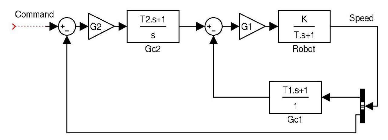
The robot's onboard controller is a velocity feedback loop for each wheel. In our architecture each wheel is controlled independently, so part of the task was to design a controller that would be robust to the variation in characteristics depending on how the robot is driving. The robot was commanded with a step of velocity which yielded first order characteristics with parameters show in the table below.
Table 1: Parameters for plant in different modes of operation. In the form K/(sT+1)*
| Mode of movement | Tau (T) | DC Gain (K) |
|---|---|---|
| Spinning | 0.1 | 3.25 |
| Forwards | 0.19 | 2.45 |
| Sideways | 0.20 | 2.01 |
Due to this variation a minor loop controller was used. A continuous time equivalent is shown in the diagram below. This controller yielded a robot which responds much faster and has better steady state performance.
6. Acknowledgements
We could not have made it this far without the support of our sponsors: School of Engineering and Applied Sciences at Harvard University and the Edgerton Center at the Massachusetts Institute of Technology. We would also like to give special thanks to Radhika Nagpal of Harvard University and Stephen Banzeart of the Edgerton Center at MIT.
References
- Browning, B. et al, "STP: Skills, tactics, and plays for multi-robot control in adversarial environments" in Proceedings of the Institution of Mechanical Engineers, Part I: Journal of Systems and Control Engineering, 2005
- Robinson, D. et al, "RoboCup Team Description Paper: RFC Cambridge", 2009
- Zickler, S. et al, "SSL-vision: The shared vision system for the RoboCup Small Size League" in RoboCup 2009: Robot Soccer World Cup XIII