RoboJackets 2011 Team Description Paper
Alex Cunningham, Stefan Posey, Ben Johnson, Stoian Borissov, Anthony Gendreau, Nikolaus Mitchell
Georgia Institute of Technology, Atlanta, Georgia, USA
Abstract For the 2011 RoboCup SSL season, Georgia Tech RoboJackets RoboCup SSL team has finished mechanical work and completed new electronics testing on the system that was outlined in the previous year's TDP. This year will see the full roll out of both new mechanical and electrical hardware for both the new and prexisting fleet. Software has improved motion planning and gameplay. The new robot fleet includes many incremental improvements over the 2008 design to address deficiencies in the previous design, as well as the addition of a chipper and wheel encoders. This document describes our overall system, with a focus on the improved software system, new electrical design, and mechanical content not present in the 2010 TDP.
System and Team Overview
The overall system is comprised of three subsystems, with corresponding subteams:
Mechanical designs and builds the physical robot chassis, including the drivetrain and mounting all of the components within the robots.
Electrical designs and builds the control circuitry for the robots, the kicker solenoid system, and the radio communications modules.
Software handles control of the robots from the main computer, including world modeling, low-level control, and high-level strategy and planning.
While the subteams can work on particular parts of the project, many areas involve significant collaboration between subteams, such as the design of the solenoid, or the sensor design relevant to control. There are two main areas of integration: prototype design and field testing. In prototype development, the mechanical and electrical teams collaborate to design, build and test all of the physical components of the system, and undergo design reviews from the rest of the team before starting construction on the new fleet. The software team works in parallel, using a combination of a simulator system and the 2008 robot fleet to develop the necessary software to drive the robots for competition. By exploiting existing resources, the team can produce a robust software package ready in time for testing when the new fleet is finished.
For 2011, our strategy is to improve on previous performance on three fronts. One significant undertaking completing construction of a new fleet, which incorporates many of the lessons learned from the previous fleet in terms of reliability and performance, as well as the addition of new features, such as a chipper. The new fleet design also includes the next iteration of our control electronics, which include and make on-board use of new sensing facilities, such as encoders and an IMU. Software has focused on building more robust motion control and reliable open-field gameplay. These improvements will combine to produce robots that are more capable and competitive than the previous design.
Software
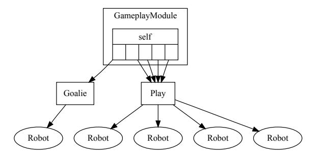
To address the shortcomings of previous software systems and exploit the capabilities of the new fleet of robots, we are making several significant changes to the robot control software. In previous years [1], due to the lack of motion sensors on the robots, we performed all motion control, including wheel control on the off-board computer, which bounded the precision and responsiveness of robot movement. In 2010 [2], we experimented with a sophisticated optimization-based pass planning system designed to provide robust passing, but this system proved to be ineffective outside of simulation due to the movement and shooting precision of the real robots. Previous years have also relied on a streamlined Skills, Tactics, Plays (STP) [3] architecture, with our behavioral system illustrated in Figure 1, and been constructed with a series of hand-tuned state machines with a large number of parameters to tune.
To address these shortcomings, the new software system improves the design in several ways:
- Simplified continuous play design
- Unified motion planning framework to plan for a team of robots at a time
- Moving local robot control and pose estimation to robots
- Improved logging and simulation
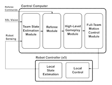
The architecture for the 2011 system is illustrated in Figure 2, with some of the functionality from the previous designs moved onto the robots, and delayed motion control to allow for full-team planning.
Play Design
In previous years, we focused our play design efforts on creating hierarchical state machines to describe plays for the robots. While this state machine approach has scenarios in which it is effective, particularly during simple restart plays or situations that are actually discrete, we have found designing open gameplay plays to be difficult to manage. In particular, even simpler tasks, such as driving to and kicking the ball became a complicated set of states with corresponding parameters for hysteresis thresholds, timeouts, etc.
To address this flaw, we are redesigning the play structure to focus on modeling general gameplay as a fundamentally continuous system with infrequent discrete events, such as kicking the ball. This system will be implemented using a goal mixing protocol that allows for smooth transitions between robot target positions and natural hysteresis between objectives.
Unified Motion Control
While the previous implementation of motion control used a simple dynamicsconstrained RRT[4] for planning the path of a single robot, this approach has the significant flaw that it does not account for the positions of other robots in the team. This results in robots driving into each other while attempting to reach a goal, or in many cases, no robot being able to reach the goal.
Based on recent work using more sophisticated RRT algorithms, such as RRT*[5], providing optimal robust path planning in high-dimensional spaces, pursuit-evasion algorithms[6] as well as replanning techniques [7], we will execute motion planning for the entire team. As these sampling-based algorithms are designed for high-dimensional spaces, we will plan for the whole team of robots as a single RRT system and build reusable set of path trees through the space of all robots. In this way, we can avoid having robots collide with each other and achieve full-team optimal path planning under the constraints necessary in a RoboCup match.
To incorporate this into our plays/behaviors model, we simply delay motion planning until after choosing goals and constraints for all robots and then execute planning, rather than creating plans for each robot separately. Because the random tree generated by these algorithms is actually optimal and obstacles slowly moving, we can keep the tree between frames and update it incrementally, rather than using full replanning at each frame.
One feature of the new fleet that will aid in improving motion planning precision is the move of local control and pose estimation to the microprocessor on the robot control boards. Because of the improved sensing of robot motion from the new encoders and IMU, much of the difficulty with controlling and modeling the robots will be handled by closed-loop control, leaving the off-board computer to manage the higher level planning tasks.
Logging and Simulation
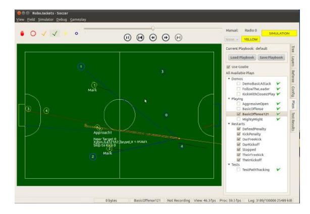
In addition to improving gameplay and motion planning, we have been steadily improving the interface and development approach used in the control software. After difficulties with logging during the Singapore, we added a much more robust system, capable of providing instant replays, saving full system states at each frame to replayable logs, and easy-to-use visualization for debugging and monitoring. The improvement to our tournament debugging capabilities was especially evident during the 2011 US Open. A screenshot of the current software system running a multi-robot demo is shown in Figure 3.
In addition to improving the logging facilities, we also plan to rework our simulator to improve the physics modeling and provide more accurate models of robot behavior, particularly with the addition of the chippers to the robots. The previous simulator used a largely unsupported version of PhysX, can produce a reasonable facsimile of robot physics, but there are frequent simulator glitches where the ball can disappear and reappear miles away, making actual gameplay testing difficult. In addition, the motion model for the robots has been rather incomplete, making simulation results differ wildly from real-world robot operation. To address these problems, we will reimplement the simulator using Bullet, an open-source physics library with more up-to-date support and parameterize the motion models used on performance data from actual robots.
Mechanical
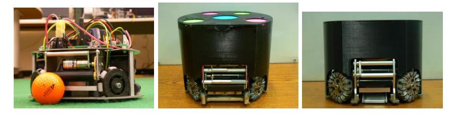
While our previous robots conducted sucessful gameplay, we have continued developing a new team with increased capabilities for the 2011 season. In particular, the new robots feature a refined chipper and kicker assembly that has gone through additional changes since last years submission. Lessons learned in competition and testing of the 2008 fleet motivated us to place special emphasis on increased manufacturability and reliability. Testing and validation of new parts follows many of the same methods outlined in our 2008 Team Description Paper (TDP) [1]. At present the new team is no larger than 179mm in diameter and 149mm tall.
Reliability, Manufacturability, and Maintainability
A number of improvements were implemented to enhance manufacturability, reliability, and maintainability of the new team. In an effort to contiune utilizing the 2008 fleet in a more robust testing and mixed team role, some of these improvements have also been implemented in the form of new parts and assemblies for the previous robots. These new designs for the 2008 robots include a new dribbler, a new shell, and new omni wheels. Since the publication of last year's TDP the new fleets drive modules and omni wheels were manufactured and assebled as presented in the 2010 TDP. For additional information on drive modules refer to the previous years paper.
Omni Wheel
The new wheels sucessfully addressed a few key problems with the 2008 design regarding carpet fiber build up and cleaning. To address carpet buildup the rollers now have tapered edges, and many previsouly sharp points on the outter wheel rim are now rounded. To simplify cleaning procedures the new fleet uses a small dowel pin as an axel for each roller and a polygonal groove for the inner mounting ring. A new version of the 2008 wheels which feature many of the same improvments has been designed and await funding for manufacturing. Both designs share many of the same parts such as rollers, o-rings, and fasteners. They differ in size and mounting requirments for their respective drive systems.
Dribbler
The dribbler is the assembly which controls the ball during gameplay. The mechanism utilizes a custom steel pinion shaft covered with silicone rubber tubing to increase adhesion. Just as in 2008, a Maxon EC16 brushless motor mated to a GP16A planetary gearhead spins the dribbler shaft through a simple 1:1.4 gearbox. The use of ball bearings rather than bushings increase efficiency and a larger tooth size decreases susceptibility to foreign object contamination. Additionally, the assembly incorporates a break-beam ball sensor. The dribbler's ball coverage is no more than 19%. In addition to gearing changes we have updated the routing of the ball sensors. The 2008 fleet encountered problems with the wires of the ball sensors getting caught in the wheels. Thus, the ball sensors now come from the top, and stay clear of the wheels. The 2008 fleet design was also updated with a dribbler system similar to the new fleet.
Kicker & Chipper
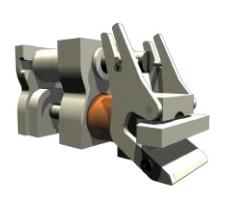
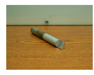
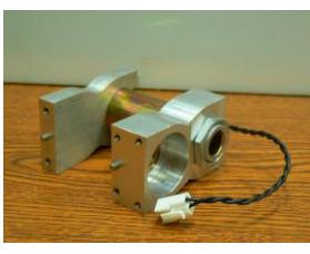
Since last year, many changes have been made to the chipping and kicking ball control system. The two most promninet being the integration of the the chipping and kicking harward into one assembly and the move to a bimetallic kicker plunger. This system is composed of two off-the-shelf solenoids. For the kicking functionality of the system, the solenoid had its casing removed to fit within dimensional restrictions. The kicker plunger is made of a front aluminum component and a rear steel component. The use of aluminum reduces energy losses due to the solenoid's magnetic field pulling back on the plunger after it has been fired. A spring, which has a much longer life than rubber bands, is used to return the kicker to a consistent starting position after every kick. This will aid in predicting the behavior of the kicker plunger during firing. Additionally, a more robust kicker boot has also been implemented which, unlike the 2008 kicker boot, does not require side reinforcement to prevent bending under the large forces encountered while kicking the ball.
The chipping componet allows the robots to pass the ball into the air. It can shoot the ball over opponents and adds greater flexibility to planning algorithms while reducing chances of interception. The chipper boot is located underneath the kicker boot. The chipper is powered by a solenoid which is mounted above the kicker solenoid. In order to transfer power from the solenoid to the chipper, two arms are used that act as levers. The arms translate the horizontal movement of the plunger to the chipper boot by a 4:6 ratio. When the solenoid fires and pulls the plunger back, the arms rotate and move the chipper boot forward and up, chipping the ball. In order to prevent the chipper solenoid from coming apart while firing, its ends are held in place with aluminum supports. Variations in arm geometry are being considered for optimal chipping performance. During prototype testing, a thirteen foot chipping distance was achieved.
Shell
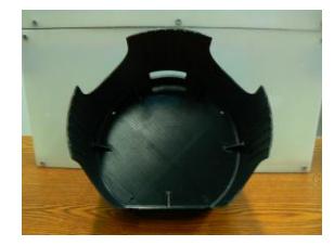
A 3-D printed ABS-plastic shell design is implemented in the new fleet as well as the old 2008 fleet. These printed shells are much easier to fabicate as compared to the previous oven baked designs and saw field testing during the 2011 North American SSL Open. Slots built into the top of the shell allow for easy changing of dot patterns. These slots elminate the need to cut out dots and tape on paper tops. The shells also feature openings that allow for turning the robots on/off and visual access to indiator lights on the electrical boards. Due to the nature of 3-D printed ABS plastic Finite Element Analysis and impact testing was performed to assess the implementation of ribs and gussets. A balance between flexibiliy and rigidity was ultimately achieved wich mitigates cracking along the grain of the part.
Electrical
This year we have made major improvements to the control electronics on our robots. We have added sensors, switched to a more capable CPU, and made many firmware improvements to help development and operations. The new electronics will also be used as upgrades to provide some improved capabilities to our earlier robots.
Radio
For our 2008 robot fleet, we designed and constructed a 900MHz halo antenna. A halo antenna is a ring of heavy-gauge wire with the feedline's ground attached at one point and a gap directly opposite this point. A gamma match arm made of smaller wire leads from a capacitor at the feedline to a point further around the ring. This antenna provides coverage in a plane similar to a dipole but with minimal height. The antennas were made from bent solid copper wire and required individual tuning after installation in the robot. This antenna design is very sensitive to variations in dimensions, which resulted in significant variation in performance between antennas. To reduce the time required to tune each antenna and to make the antennas similar in bandwidth and return loss, we produced new printed halo antennas. The new antennas are normal printed circuit boards on FR4 material. The printed pattern has dimensions similar to the original halo. While our original halo design required two adjustments, one trimmer capacitor at the feedpoint and one sliding copper plate near the gap, the new antennas require only the feedpoint adjustment. Since the antenna is sensitive to any nearby metal objects, the antenna is mounted on standoffs near the top of the robot and the connector used to feed it is a right-angle MMCX connector on the edge of the board. This choice of connector eases assembly and keeps the coaxial cable away from the antenna except at the feedpoint.
We continue to use the Texas Instruments CC1101 single-chip radio, but with a ceramic balun/filter to replace the numerous capacitors and inductors we used previously. The radio protocol has been changed to allow more data to be transferred between the control computer and the robots. All robots are now able to report their status (such as ball possession and diagnostic data) at 60Hz. The protocol is time-multiplexed half duplex: the control computer sends one packet containing commands for all five robots on a team, and each robot is assigned a time slot in which to send its response. On power-up or loss of signal, each robot scans a preprogrammed list of frequencies looking for a valid command with its ID. To support development of on-board navigation, robot firmware can be updated over the air on all robots simultaneously.
Microcontroller
We switched from the NXP LPC2103 microcontroller to the Atmel AT91SAM7S64. The new microcontroller provides more memory, the option to increase memory while maintaining footprint compatibility, and a USB device interface. When connected by USB to a development computer, the robot appears as a serial class device and presents a command-line based interface for diagnostics, testing, and programming. No special drivers are required to communicate with the robot. While a JTAG interface is still present for debugging, both CPU and FPGA firmware can be programmed over USB without a JTAG adapter. The USB interface can be used to test all robot hardware without any radio activity, for example to allow robot repairs without interfering with an ongoing game.
Sensors
We have added many new sensors to our design. Each drive wheel has an encoder which produces 1440 ticks per revolution, resulting in a distance resolution on the ground of approximately 24µm. The wheel encoders are used for closed-loop speed control of each wheel. A hall-effect current sensor is placed in series with each motor's drive circuitry to allow measurement of the average current to each wheel. By measuring battery voltage, motor current, and motor speed, we can estimate the load on each motor and detect wheel slippage. Our goal is to optimize point-to-point motion to achieve maximum acceleration without losing positional accuracy due to slippage.
A six-degree-of-freedom inertial measurement unit (IMU) composed of an Invensense IMU-3000 gyroscope and an Analog Devices ADXL345 accelerometer allows the robot to sense its movement independently of vision. If the robot leaves the cameras' field of view, the IMU may be able to maintain a sufficiently accurate position estimate to allow it to move back on to the field. We are attempting to use the IMU to improve the robot's pose estimate to allow for more precise motion control. Our plan for future development is to move pose estimation and low-level motion control onto the robots to minimize latency and to allow us to take advantage of the IMU's motion estimates.
As in previous years, we detect ball possession with a break-beam sensor under the dribbler bar. This sensor consists of an infrared LED and a phototransistor. Previously, this sensor was frequently broken by contact with other robots because the sensors must be in an exposed location. A failure of the ball sensor gave the same indication as ball possession, requiring heuristics on the control computer to determine whether a particular robot's ball sensor was damaged. The new mechanical design better protects the sensors. The new electronics can detect four classes of ball sensor failure: LED open, detector open, detector shorted, and dazzling (excessive ambient light). If the LED or detector is mechanically damaged, the most likely result is an open circuit which can be detected and reported, allowing the robot not to be chosen for ball-handling tasks during gameplay and to be replaced at the next opportunity. To compensate for varying ambient light, alternating measurements are made with the LED on and off. If the LED-off measurement is unexpectedly high, the most likely cause is excessive ambient light, and the ball sensor will not report confident possession. By detecting ball sensor failure, we can avoid certain cases where a robot attempts to handle a ball that it does not actually possess.
Kicker
The kicker electronics have been significantly improved. This is a continuation of work started in 2010. The robot uses two solenoids for ball handling: one for kicking forward and one for chip-kicking upwards. Each solenoid is operated by discharging a pair of capacitors through an IGBT into the solenoid coil. In our previous control circuit, kick strength was determined by the length of this current pulse. The new design allows an additional control parameter: the current into the solenoid can be regulated to an adjustable value, allowing longer pulses with more carefully controlled current. This also allows the maximum current to be restricted to a value that will not damage the IGBT even with a shorted coil. The current limit is implemented by measuring the coil current with a halleffect current sensor (Allegro ACS758) and switching off the IGBT when the current exceeds the limit. When the current falls below the limit minus a small hysteresis value, the IGBT is turned back on. The robot can record coil current and capacitor voltage traces during a kick for later analysis to facilitate kicker solenoid and electronics development.
Battery
Our 2011 robots are powered by lithium polymer battery packs. Our previous robots used nickel metal hydride batteries which could not provide enough current to accelerate the robot rapidly under some circumstances. The LiPo batteries are smaller, lighter, and can provide more current without the supply voltage dropping excessively. Since LiPo batteries must not be discharged below a certain level, the CPU monitors battery voltage and sounds an alarm if the battery pack is discharged to the minimum safe level.
Conclusion
For the 2011 season, we intend to have a new fleet of robots incorporating the lessons learned through the last design revision from both mechanical and electrical systems, as well as an improved software system allowing for robust motion planning and control.
References
- Robojackets RoboCup SSL Team: Robojackets robocup 2008 team description paper. Technical report, Georgia Institute of Technology (2008)
- Robojackets RoboCup SSL Team: Robojackets robocup 2010 team description paper. Technical report, Georgia Institute of Technology (2010)
- Browning, B., Bruce, J., Bowling, M., Veloso, M.: STP: Skills, tactics, and plays for multi-robot control in adversarial environments. Proceedings of the Institution of Mechanical Engineers, Part I: Journal of Systems and Control Engineering 219(1) (2005) 33–52
- Cheng, P., LaValle, S.M.: Resolution complete rapidly-exploring random trees. In: IEEE Intl. Conf. on Robotics and Automation (ICRA). (2002) 267–272
- Karaman, S., Frazzoli, E.: Incremental sampling-based algorithms for optimal motion planning. In: Robotics: Science and Systems (RSS). (2010)
- Karaman, S., Frazzoli, E.: Incremental sampling-based algorithms for a class of pursuit-evasion games. In: Workshop on Algorithmic Foundations of Robotics (WAFR). (2010)
- Sun, X., Yeoh, W., Koenig, S.: Moving target D* lite. In: Proceedings of the 9th International Conference on Autonomous Agents and Multiagent Systems. AAMAS '10, Richland, SC (2010) 67–74