RoboTurk 2011 Team Description
Kadir Firat Uyanik, Mumin Yildirim, Salih Can Camdere, Meric Sariisik, Sertac Olgunsoylu
Department of Electrical and Electronics Engineering; Department of Mechanical Engineering; Department of Computer Engineering; Middle East Technical University (METU)
http://www.ros.org/wiki/control_toolbox · http://sariisikmakina.com · http://www.makinetanitimgrubu.com.tr/tr
Abstract This paper briefly explains the current development status of the recently reformed RoboCup Small-Size League(SSL) robot team, RoboTurk. RoboTurk SSL robot soccer system is designed under the RoboCup 2011 SSL rules so as to participate in RoboCup competition being held for the first time in Turkey. This year we have made crucial changes in the 2009's design, and in fact, all the hardware and software modules are redesigned. Most of the effort spent on the mechanical structure of the robot, motor driver board, main control board, and ROS based software architecture with the close-to-real simulation environment in Webots.
Introduction
RoboTurk RoboCup SSL robot soccer system is a project that's been studied by the members of IEEE METU Student Branch Robotics and Automation Society since 2008. However, being undergraduate students as well as dynamically changing society members slowed down the course of development considerably. After more than one year of development gap, this year we gathered a new team for the sake of hosting the RoboCup competition in our home country, and redesigned most of the modules less than a few months.
We can divide the current system into two main parts, one is the sensorimotor unit of the system namely ssl robots and the other is central decision making unit, called ssl game planner assuming that the 2-D pose of the proponent and opponent robots and the position of the ball are provided with respect to the field reference frame (viz. global information) as well as the game state is already available specifying the allowed formations of the robots under the rules of robocup ssl (i.e. referee signals).
The major improvements we have done so far can shortly be listed as follows:
- Mechanical design; we have decreased the weight of the chassis from 1.9kg to 1.4kg by the factor of almost 25% with the new design based on the Skuba, and BSmart teams' designs. Many improvements have been done on the wheels themselves and the wheel assemblies.
- Motor control board design; we have replaced the earlier control circuit which happened to be unreliable from time to time, especially during sudden changes in the acceleration.
- Main control board design; we have replaced the previous master-slave PICmicrocontroller based mainboard with the Gumstix computer-on-module centered mainboard.
- Software design; we have started developing a robocup-ssl stack on ROS. In this design, we also started adding ROS support to the ssl vision.
- Simulation environment design; we designed close to real ssl simulation environment on Webots, which enables us to simulate dynamics, frictions, collisions, and many other physical properties/events.
In the following section we state the details about the current development stage of the two main units, ssl robots, and ssl game planner. We complete with the planned extensions until the RoboCup'11 competition.
SSL Robots
In RoboCup SSL, there are five robots per team in a normal game. Each SSL robot can be investigated by considering its mechanical hardware, electronics hardware, and on-board software components.
Mechanical Hardware
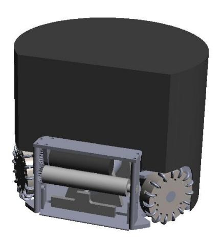
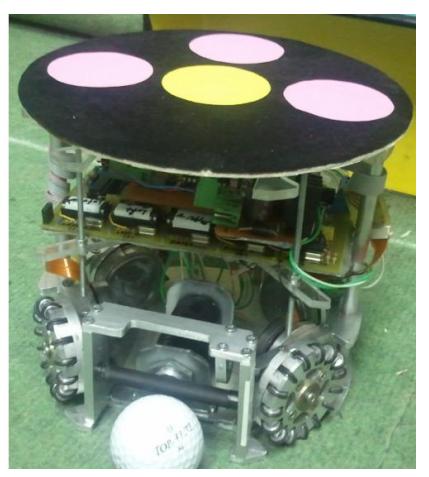
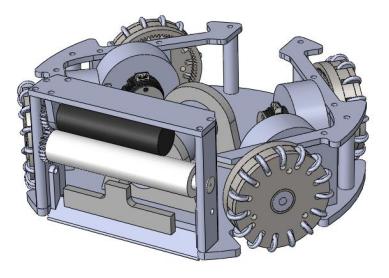
The mechanical hardware consists of the chassis, motors, kicking and dribbler mechanisms, and the omni-wheels.
Chassis is limited to the size of 18cm in diameter and 15cm in height. Previous design was more than 1900 grams; however, as a result of our latest improvements, we reduced it to 1419 grams excluding circuit boards, as it is shown in figure 2.
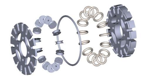
Omni-wheels are the the common choice for holonomic drive systems which enables the robot to move in all directions. In the earlier design, we used Kornylak Omni-wheels which didn't provide sufficiently smooth motion. Hence, this year we designed our custom omni-wheels. New design have a diameter of 1.968 inches and 15 rollers with rubber gaskets in order to increase grip. Omni-wheels are placed symmetrically 120 degrees apart in the front and 90 degrees at the back.
Motors Each omni-wheel is driven by a 30 Watt Maxon EC45 Flat back shaft extended brushless DC (bldc) motor with E4P encoders.
Dribbler is actuated by Maxon EC-16 40 Watt bldc motor. The material on the dribbler cylinder is chosen to be silicon rubber.

Electronics Hardware
Electronics hardware of each ssl robot consists of five main parts:
Main Controller Board houses the Gumstix COM as well as the slave controller PIC 18F4550.
Gumstix Overo Fire COM is a computer-on-module with TI OMAP3530 running at 720 MHz. It comes with many features namely, Wi-Fi, Bluetooth, DSP, PWM generator, I2C- SPI-RS232-USB interface, 256 MB flash memory with microSD slot for extra memory.
Overo Fire is responsible for every action running within the robot. Gumstix runs the following tasks:
- Reception of commands and data from the AI computer via Wi-Fi
- Counting process of encoder pulses and running PID over brushless DC motors by generating PWM
- Gathering all sensor information on robot
- Passing some of the commands to slave controller via UART
All input and output signals of Gumstix are distributed on this board. There are 1.8V-5V logic level converters for PWM output of Gumstix. Following inputs gather on this board:
- 4x 2 Channel quadrature encoder digital inputs
- 5x Ball position sensor digital inputs
The board has the following outputs:
- 5x direction output
- 5x brake output
- 6x PWM output
- 1x Sensor Board output
PIC18F4550 works as an auxiliary low level controller besides Gumstix. PIC18F4550 works as port multiplexer for brake and direction inputs of L6235 BLDC driver modules, as well as controlling the ball sensor board, controlling and measuring the kicker capacitor voltage, controlling the kicker solenoid, while isolating such power consuming areas from the Gumstix. Gumstix and PIC18F4550 use UART at 115200 bps to communicate. PIC receives the data by using RS-232 activity interrupt.
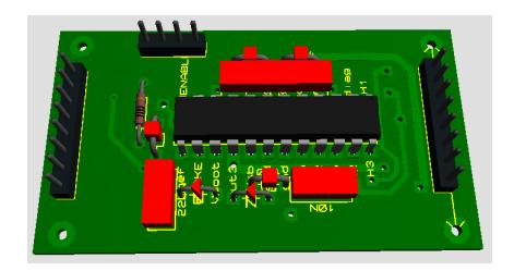
Motor Controller Board comprises L6235 as the main component, which is an all-in-one brushless DC motor driver. It has hall sensor input form the brushless motors, Maxon EC45 flat, and logic decoder for determining the direction of the motor and power MOSFETs to drive the motor. Also, it has digital input pins for motor direction, brake and speed. Each module has one L6235N IC and responsible for one brushless DC motor. One PWM, one brake and one direction input are hooked up to the each module. Modules are supplied with 5V for digital part and 14.8 V for actuator part. Modules are designed in a way that they can be mounted successively. 5 modules exist in each robot: 4 modules for EC45s, 1 module for EC16 dribbler motor.
L6235 BLDC module is also the part where the encoders are connected. Therefore, encoder inputs also come from this board. The reason to connect encoders to motor board is that each motor input and encoder outputs would be taken from the same connector; therefore, each connector represents a motor with its whole control.
Kicker Controller Board Kicking control circuit contains a DC-DC booster to charge a capacitor, and a capacitor discharging circuit for main kicking solenoid. It supplies a feedback for voltage stabilization at 200 Volts. The controller of this booster is the PIC18F4550 whose duty is to supply PWM for booster toroid and maintain a stable capacitor voltage. A 200 V, 2000uF capacitor is charged by DC-DC booster up tp 200 V in less than 4 seconds. A simple voltage division method and ADC conversion is used to determine the capacitor voltage. The capacitor is discharged on a tubular push type solenoid S-20-100-H which has approximately 3500 turns @ 25 awg . A power transistor is responsible for switching of the discharge. The kicking action is started by Gumstix command to PIC via RS232 and PIC184550 activates the switching MOSFET. As a result the ball can be shot with the speed of 6.5 m/sec.
On-board Software
Onboard software runs on each robot so as to make the robot behave according to the game plan provided by SSL Game Planner. Onboard software is composed of two main components namely, kernel level software and application level software.
Kernel Level Software includes kernel modules and low level I/O devices that run as part of the Linux kernel. As GNU/Linux distribution Ubuntu 10.10 is chosen since it is compatible with ROS, which application level software is based upon. Ubuntu runs on the Gumstix Overo Fire with Summit expansion board.
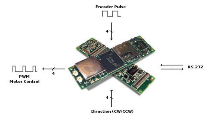
Kernel level software fills the gap between the application level software and the hardware such as DC motors, microcontrollers, etc. As depicted in the figure 5, four lines of PWM output are generated on Gumstix by using PWM generation module to drive bldc motors connected the four wheels. The generated PWM output is controlled by Application Level Software with using ROS control toolbox to apply closed-loop control. Besides, it acquires the four 2-channel signals which are generated by the encoders to indicate speed and direction values of the motor.
In addition to the information related to dribbler and kicker, ball sensor data is also transmitted and received via UART with RS-232 protocol.
Application Level Software is a ROS node in the ROS network. These nodes represent the SSL Robots in this network. Communication between SSL Robots and SSL Game Planner is achieved by the message-passing mechanism of the ROS. All required data and commands needed to be performed are sent through publisher/subscriber mechanism. In this two-ended architecture, SSL Game Planner and SSL Robot mutually subscribe to each other.
SSL Robots are subscribed to the robot command messages which are published approximately at 60 Hz frequency by SSL Game Planner in order to make robot actuate according to the game plan. Robot command message contains following data fields within:
- Translational speed (in m/s)
- Translational direction (in radian)
- Rotational speed
- Rotational direction (CCW or CW)
- Dribbler speed (rpm)
- Kicker speed
- Local state request
On the other end, SSL Game Planner is subscribed to the local state messages which are published by SSL Robots in order to acquire local state information of the robots. Local state message contains following data fields within:
- Ball possession
- Battery level
- Temperature level
SSL Robots updates its local state information regularly acquiring related data from its hardware. If the ball possession condition is changed, then the message indicating this will be published in order to notify SSL Game Planner. Besides, if the robot command message includes a local state request then it will also published to indicate current state of the robot.
SSL Game Planner
SSL game planner unit can be investigated from two perspectives, software architecture. and planning methods.
Software Architecture
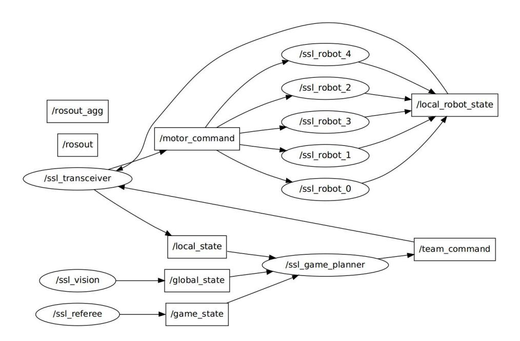
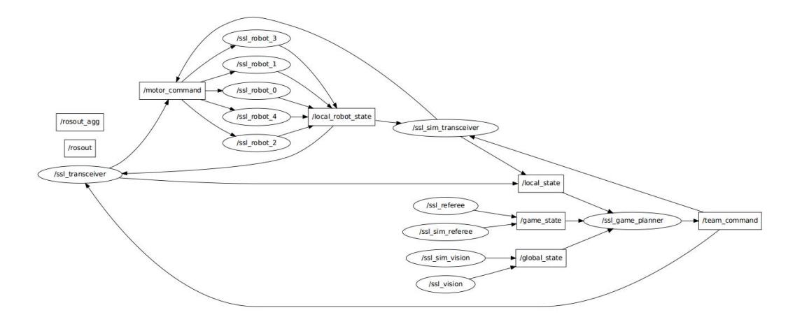
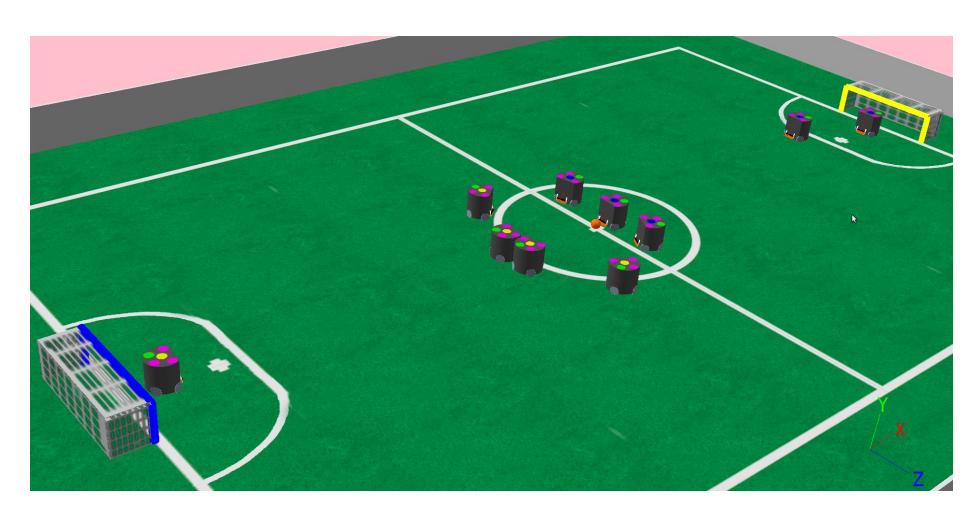
This year, we designed our system by heavily using ROS graph concepts to establish communication between the processes which are the nodes in ROS network. Thanks to the message-based communication architecture, we can easily replace the real robots with the simulated robots and ssl-vision with the sim-vision (simulated vision) or the ssl-referee-box with the sim-refree (simulated refree) by making no change in the source code whatsoever.
Current architecture is shown in the figure 8. Most of the nodes are currently under development and some of them are stub at the moment (viz. ssl refree, ssl sim refree and most importantly ssl game planner).
This graph probably is going to be more simplified during a real game as it is shown in the figure 6
We are also working on adding ROS support for the ssl-vision mostly developed by Zickler et.al and became the standard vision system for the RoboCUP SSL.
We are using Webots simulation environment for developing path planning algorithms and state estimation filters as they are explained in the next section. Since Webots is a commercial simulator and we are using trial version -soon going to be expired-, we are considering to move our simulated robot design to the Gazebo by using URDF and Xacro language, depending on our financial status. This alternative seems to be reasonable since ROS fully supports Gazebo simulator, and it is already included in several ROS distributions.
Planning Methods
We reached to the stage where ssl-robots can realize the commands given by ssl-game-planner without colliding to the statical obstacles, following the path close to the optimal/shortest path. In order to accomplish this ability, ssl-robots should be able to project the velocity commands to each of the wheels that is where Motion Control module plays the role.
Obstacle avoidance is satisfied with the well-known artificial potential fields method. We have improved the method based on the object-grouping method proposed in [4], which is explained in detail in the following sections.
Motion Control: Current robot design has an assymmetrically distributed four-omni-wheel base. Wheel angles are, from the vertical line where robot points upward are $53^{\circ}$ in the front and $45^{\circ}$ at the back. Motor velocities can be obtained by using the following equation, where :
$$\begin{bmatrix} v_1 \ v_2 \ v_3 \ v_4 \end{bmatrix} = \begin{bmatrix} sin(\alpha) & -cos(\alpha) & -r \ sin(\beta) & cos(\beta) & -r \ -sin(\beta) & cos(\beta) & -r \ -sin(\alpha) & -cos(\alpha) & -r \end{bmatrix} \begin{bmatrix} v_x \ v_y \ \omega \end{bmatrix}$$
In simulation, motors are currently controlled with PID controller, yet it is not added to the actual robots since there are no encoders mounted to the motors, yet.
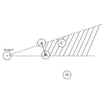
Path planning: In the traditional artificial potential fields, every obstacle is handled seperately, which prevents observing the overall picture of the environment. In this approach, visibility and proximity of the obstacles are also taken into consideration. For instance, the obtacles which are close enough to each other are considered as one obstacle(virtual) by grouping. Besides the obstacles which are not visible to the agent -because of the other obstacles between themare not considered as obstacles which decreases the oscillations.
First, a linkability metric, say LINKDIST, should be defined which specifies when to link obstacles. According to LINKDIST obstacles are linked to each other starting from the nearest obstacle in the path. While linking, obstacles are checked if they are visible to the agent. If an obstacle is not visible, it is simply discarded.
An obstacle is considered only once during linking process. That is, linked obstacles form a linked list data-structure.
After linking, linked obstacles are merged to form a single obstacle which has a proper radius so as to include all of the obstacles. The result of this process is virtual obstacles which are used to apply repulsive forces on the robot.
With this method, we get rid of the local minima and oscillations problems that are commonly encountered potential field based methods.
Algorithm 1 Obstacle Programming
while preObstacleList.size() > 0 do
  closestObstacle ⇐ getClosestObstacle()
  if isV isible(closestObstacle) = T RUE then
    tempObstacle ⇐ closestObstacle
    repeat
       if isLinkable(tempObstacle, preObstacleList[i]) = T RUE then
         linkObstacles(tempObstacle, preObstacleList[i])
         tempObstacle ⇐ tempObstacles → Neighbor
       end if
    until preObstacleList.size() = 0
  end if
  virtualObstacle ⇐ closestObstacle
  groupObstacles(virtualObstacle)
  postList.pushback(virtualObstacle)
end while
Game Planning: Our system is not able to perform higher level behaviors for the time being. We have successfully implemented ball tracking behavior for the real robots, but without encoders mounted on the wheels, robots are not able to respond to the precise rotational actions. Due to this situation, ball-related behaviors are not developed yet.
However, we are planning to stick to the commonly used hybrid deliberative/reactive control architecture and divide the planning problem into different stages such as strategy, roles and skills, as it is explained in [7].
Conclusion and Future Work
In this document, we have shown the current development stage of the Robo-Turk SSL robot soccer system. We have emphasized the major changes in the mechanical design, motor control board, and software architecture. New robot design will enable the system to react quickly to the changes in the game state, as well as perform more efficient than the robot design we have developed in 2009.
With the very young and motivated team members (Mumin, Salih and Meric second and first year, Sertac fourth year undergraduate students, and Kadir being first year MS student) we are planning to attend RoboCup'11 Turkey for the first time.
Acknowledgments. Many thanks to the METU EEE department for providing us with a laboratory to work on a RoboCUP project, and to the IEEE METU Student Branch for their endless moral support. We also very grateful for their support in the construction of the prototype robots, to Sariisik Makina. Lastly, it wouldn't be possible without the financial support of OAIB.
References
- Quigley M., Conley K., Gerkey B., Faust J., Foote T. B., Leibs J., Wheeler R., and Ng A. Y. (2009). Ros: an open-source robot operating system. n International Conference on Robotics and Automation, ser. Open-Source Software workshop.
- Michel, O. Webots: Professional Mobile Robot Simulation, International Journal of Advanced Robotic Systems, Vol. 1, Num. 1, pages 39-42, 2004
- S. Zickler, T. Laue, O. Birbach, M. Wongphati, and M. Veloso: SSL-Vision: The Shared Vision System for the RoboCup Small Size League. RoboCup 2009: Robot Soccer World Cup XIII. Pg:425–436
- B. Zhang,W.Chen, M. Fei, An optimized method for path planning based on artificial potential field, Sixth International Conference on Intelligent Systems Design and Applications (ISDA'06) Volume 3 (2006)
- Wasuntapichaikul P, Srisabye J, Sukvichai K. Skuba 2010 Team Description. 2010.
- Laue T, Fritsch S, Huhn K, et al. B-Smart Team Description for RoboCup 2010.
- Gurzoni, J. A., Martins, M. F., Tonidandel, F., & Bianchi, R. a C. (2011). On the construction of a RoboCup small size league team. Journal of the Brazilian Computer Society, 17(1), 69-82.