Tigers Mannheim (Team Interacting and Game Evolving Robots) Team Description for RoboCup 2011
Bernhard Perun, Andre Ryll, Gero Leinemann, Peter Birkenkampf, Christian König, Gunther Berthold, Stefan Scheidel
Department of Information Technology, DHBW Mannheim, Coblitzallee 1-9, 68163 Mannheim, Germany; Department of Mechanical Engineering, DHBW Mannheim, Coblitzallee 1-9, 68163 Mannheim, Germany
Abstract This paper presents a brief technical overview of the main systems of Tigers Mannheim, a Small Size League (SSL) Team intending to participate in RoboCup 2011 in Istanbul. First there is a description of our hardware system followed by our software modules. Furthermore an outlook displays the upcoming goals of our team.
1 Introduction
Tigers (Team Interacting and Game Evolving Robots) Mannheim is a team of students of the Cooperative State University Baden-Wuerttemberg Mannheim, intending to participate for the first time in the Small Size League (SSL) at RoboCup 2011 in Istanbul. After two years of development we are finally able to participate with other teams in this international tournament.
Due to the fact that we decided to publish all our available source code and documentation of our system after RoboCup 2011, this paper should give an overview of our system only. Everyone who is interested in special parts of our soft- or hardware may freely download it from our website after the tournament. We believe that the most benefit is given to the community when all parts of our system can be accessed by everyone who is interested in.
This paper is divided into three sections. First the hardware is described. One may note that our mechanical and electrical designs are inspired by a lot of other teams. It would have been more difficult to develop our hardware system without the helpful community. Many thanks for that. In the next section, an overview over the software our main control software and our simulator - is given. At last there is an outlook on what we will be able to finish until RoboCup 2011 and also on some long term goals for the next years.
2 Hardware
(Section with subsections)
2.1 Mechanical System
Drive:
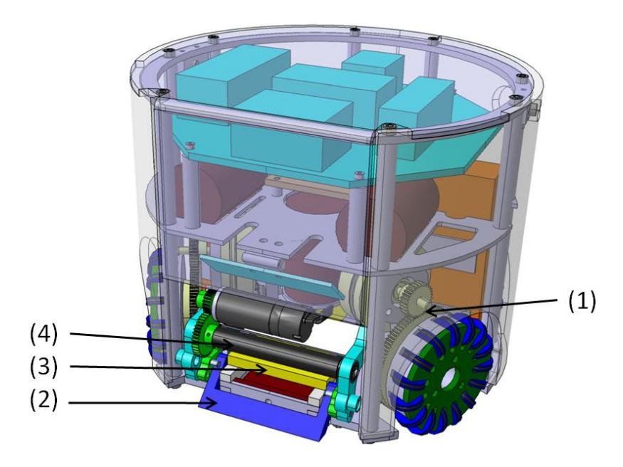
The omnidirectional drive of the robot consists of four wheels with fifteen transverse rollers (assembly of aluminum "rim" and a nitrile rubber "tyre") that are driven by one Maxon 30W EC-drive each. Torque is converted by steel gearwheels with a gear ratio of about 3.33 (Figure 1, (1)). Thus the drive is optimized for high acceleration (top speed is reached in less than one second even if acceleration starts while the robot stands still) and little residual heat build-up inside the motors. Nevertheless, the robot achieves a top speed of approximately 3 m/s when driving forward.
An optical encoder is attached to each wheel's shaft to detect the twisting angle of the wheel with high precisions. In order to be able to mount the encoder at the end of the shaft, the wheels are fixed by positive connection to the shaft and the shaft itself is mounted in dry lubricated friction bearings in a specially designed bearing block.
Kicking Device:
Our Kicking Device consists of two parts: the straight kicker (Figure 1, (2)) for kicking the ball straight forward and the chip kicker (Figure 1, (3)) for lobbing the ball. Both are designed as electromagnetic actuators for fast and powerful shots.
The dribbling roller (Figure 1, (4)) is covered by a silicone layer optimized for high friction and thus makes driving backwards, without losing the ball, possible. The dribbling shaft is driven by a Maxon 15 W EC-drive and a gear drive with a gear ratio of 2.
Case:
The outer Case of the robot is made of polycarbonate. This material offers an elongation at break three times higher than standard Perspex (polymethyl methacrylate). Thus even high impacts can not damage the housing.
Moreover, the materials density is less than half of the aluminum's and thereby it reduces the total weight of the robot.
Measurements:
External diameter: 180,00 mm Height: 148,00 mm Maximum ball coverage: 15,29 %
2.2 Electrical Design
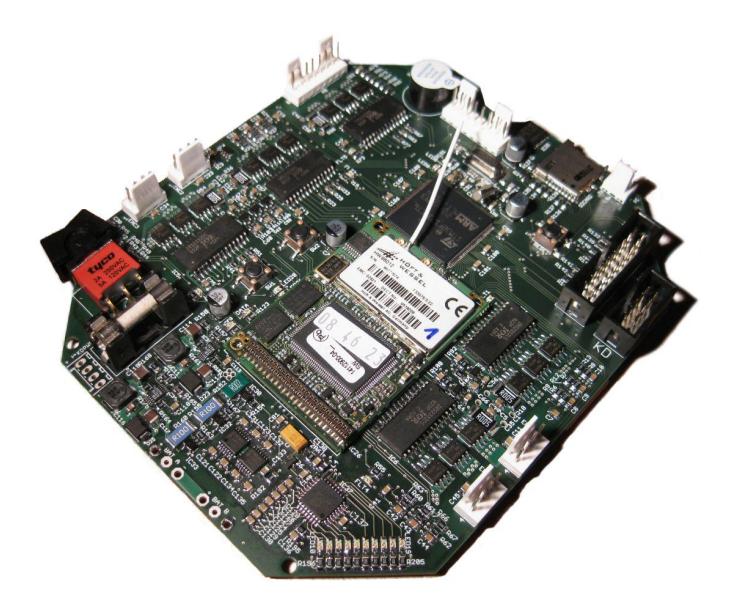
The electronics of our robot consists of three distributed boards, each of them serving a special purpose. All boards are self-designed to fit the special need of the SSL requirements. Furthermore all parts are still large enough to be soldered by hand. The most important board is the mainboard, a 140x120mm 4-layer PCB which is shown in Figure 2. Its main processor is a Cortex-M3 32-bit microcontroller from STmicroelectronics (STM32F103ZE) clocked with 72 Mhz. The processor is capable of controlling all five motors, reading the encoders and managing wireless communication. Due to the heavy usage of hardware interrupts, the motors can be controlled with a PWM frequency of approximately 16 kHz without significant impact of the other tasks' performance. To manage various tasks the FreeRTOS (http://www.freertos.org) real-time operating system is used. To communicate with the main control computer and to receive commands, an embedded DECT module from "Höft & Wessel" (HW86012) is mounted onto the mainboard. The module uses a frequency of 1.9 Ghz and transfers raw ethernet frames to the Cortex. An UDP/IP stack then decodes the commands. The mainboard is completed by two ATmega microcontrollers (8-bit) from ATMEL, which act as port expanders and AD converters. For the communication between the MCUs a SPI bus is used.
To control the kicker, a separate board is used which also uses the SPI bus to communicate with the mainboard. Different from most other teams, which use a stepup converter to charge the capacitors, our system uses a flyback converter. Its most important part is a line output transformer, converting the low battery voltage to the needed, higher voltage. The kicker board is designed to be safely used with capacitor voltages up to 400 V. Together with four 470 uF capacitors this system can store energy of up to 150 J. To control the energy flow to the kicking solenoid, high-power IGBTs with mounted heatsinks are used. The complete board is controlled by an ATmega microcontroller, which uses built-in PWM outputs to control the charge and discharge transistors. Furthermore it monitors the capacitor voltage and heatsink temperatures. The flyback converter circuit, together with the separate controller, can charge the capacitors to full level in under 10 s. With an optimized discharge control the kicker speed reaches the league limit of 10 m/s.
The last daughter board is mounted above the dribbling bar and controls four IR sender-receiver pairs. One of these pairs acts as a lighting barrier to detect a ball in front of the robot. The other three pairs can be used to check if the ball is correctly centered in front of the robot. As the other board, this board also uses a dedicated ATmega and communicates via SPI with the mainboard.
All in all, the electronics consist of one Cortex-M3 at 72 Mhz and four ATmega168 at 12 Mhz. Additionally to the already mentioned features, the mainboard also has two accelerometers for motion detection, a buzzer to signal fatal problems, motor current monitoring circuitry, an RS-232 interface, microSD card slot and a full-speed USB client port.
To power the robot, two Lithium-Polymer batteries are connected in series to supply a nominal voltage of 14.8 V. With a charge of 2400 mAh the robot can run at least a whole match of 20 min without the need to change batteries.
3 Software
(Section with subsections)
3.1 Overview
An important decision we made at the beginning of our project was to write all software, not running on the robot, using the JAVA programming language. Due to the simple structure and its compatibility, it is easier to work with within a big development team, compared to other programming languages. At the moment there are no major performance losses or other disadvantages compared to C++, referred to the SSL environment.
Our software system consists mainly of two programs: the simulator "Tigers Cage Simulator" and the main control software "Sumatra". The simulator has been programmed for testing our Artificial Intelligence (AI) in a virtual environment. This part is described in section 3.7 in more detail.
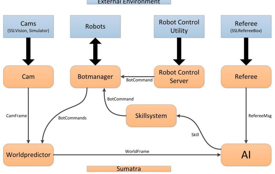
Sumatra interacts directly with the SSL environment. The software is responsible for getting the current image-data from SSL-vision, reacting to the newest referee instructions, calculating the best strategy for the next interactions for the robots and sending the resulting commands to the robots. Of course, Sumatra can also interact with our Simulator, so no real environment is needed.
Sumatra is internally divided into seven sub-modules which are described in section 3.2 – 3.6. To handle this sub-modules a module system called "Moduli" (http://moduli.sourceforge.net) is used. Moduli is a self-programmed, very fast module system for JAVA which is designed to serve our needs exactly. In Sumatra it functions as model in our MVP[8]-architecture.
In Figure 3 there is an overview concerning the SSL environment and the internal structure of Sumatra.
3.2 Module "Botmanager"
The Botmanager is the most low-level module in the stack to communicate with the robots. It manages an inventory of all available robots and controls the connection and disconnection procedures. The commands, which are sent to the robots, are the most low-level one in our software, such as "setVelocityX/Y" or "armStraightKicker". Furthermore it stores all parameters for each robot and ensures that these are set as soon as a robot is connected. Besides the obvious management of robots, this module also acts as a converter between the internal Java commands and the UDP packets sent to the robots. To optimize bandwidth usage, the Botmanager may wait for several commands and group them before sending them to the robots. This method reduces protocol overhead. To ensure smooth control of the robots, a maximum wait time for the Botmanager to collect commands can be configured and is usually set around 20 ms.
A planned addition to the Botmanager is to collect commands to all robots simultaneously, group them in a large command and send them via multicast. This should further reduce protocol overhead and thus the time to process commands on the robot.
3.3 Module "Worldpredictor"
"Sumatra" has to be aware of the current position, orientation and motion vector to successfully control a robot.
The position of the objects on the field is provided by the standardized image recognition software SSL-vision [1]. This program processes each frame of each camera separately and sends position data of identified objects via UDP to the teamservers. Henceforth, these results are referred to as CamFrames. The position data is noisy since, due to real-time processing, the resolution of the cameras is limited and the localization algorithm is quite unstable on changing light conditions. Furthermore, received packets contain only information about the past of the game because of the processing and transmission time. In addition, received CamFrames do not have to be in a specific or correct order and show only part of the field (caused by the lens coverage of one camera).
The Worldpredictor module receives and processes this information.
Therefore it merges the information of different CamFrames and controls the adding and removing of objects to the field. In addition, it is designed to process the CamFrames in correct order, filter out noise of the data passed by SSL-vision and calculate the current state of the game by predictions based on the CamFrame-state. The result is a WorldFrame, describing the current state of all objects on the whole field.
We assume that there will be only few false positive robot observations delivered by SSL-vision. That is why we detect objects added to the field simply by counting the number of observations in a specific period of time. If we have multiple observations of a so far unknown object in a couple of CamFrames, the object will be added to the WorldFrame. The other way around, known objects are removed if the last observation it appeared in is too old. Since we believe that the removing and adding of objects are no time-critical actions, this proceeding seems sufficient to us.
We use an Extended Kalman Filter (EKF) [2] for filtering out measurement noise and predicting the current state of known robots and balls on the field. The performance of our filter was improved by implementing a collision model, which reinitializes the filter when two objects are likely to collide [3], and improbability filtering, which allows us to ignore unlikely observations [4].
The EKF uses different velocity-based motion models [5] for the objects on the field. Due to the absence of other information sources, the ball's motion model is simply based on the information delivered by the CamFrames. Due to the linear uniformly accelerated nature of its movement, we get quite good results nevertheless. In contrast, a robot's motion is indeterminable by using CamFrames only. Because of that, we include the robot's control commands we get from the Botmanager module into the motion model. This merging of information of different sources heavily improved the performance of the EKF compared to predictions based on CamFrames only. The control commands of the enemy's robots are estimated by interpolating between the last measurements. Since nearly all robots in the SSL seem to use the same omnidirectional approach with similar motion behaviour, these information are passed to the same motion model we use for our own robots. Nevertheless it is possible to take different robot performance into account by tuning parameters of the motion model, such as "Maximum Acceleration" or "Approximated PID slop".
3.4 Module "Skillsystem"
As the commands given to a robot are very low level, they are not very suitable to be used by the highest module in the processing stack, the AI. The AI usually has commands like "MoveTo position X,Y". This command requires additional knowledge of the environment and the current robot position. As we did not want to enlarge the Botmanager with this additional processing, the Skillsystem was added as a second level of abstraction.
The mentioned command of "MoveToXY" is implemented as a Skill. This facilitates the work of the AI and also allows reusing code. The Skillsystem gathers information about the environment from the Worldpredictor and provides it to the Skills. The Skills themselves take this information to generate one or more robot commands. The commands are then transmitted to the Botmanager which takes care of the transmission to the robots, so e.g. a "MoveToXY" skill can generate "SetVelocityX/Y" commands.
To generate a chain of actions, skills are put into an internal queue. Each robot has its own queue. The Skillsystem takes the first skill of the queue and starts processing it. A Skill is usually run multiple times until it signals it is done. The execution period can be chosen for each skill individually. After a skill is completed, the Skillsystem processes the next skill in queue. This way a chain of actions can be constructed.
Sometimes multiple skills need to be executed in parallel for a single robot. To solve this issue so called combined Skills were introduced. A combined Skill can be constructed from multiple already existing Skills. So the code already written is used to build more complex skills. As combined skills can also be made of other combined Skills, this method can become arbitrarily complex.
3.5 Module "Artificial Intelligence"
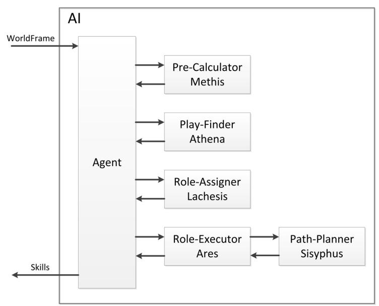
Our AI is similar to Skuba's approach in 2009 [6]. Only the structure and the meaning of some objects were partly adapted to our environment. So the module is divided into sub modules, which are supervised by an instance called Agent. This structure is shown in Figure 5. To understand the structure, it is necessary to know about the internally used data structures. These are AIInfoFrame, Play, Role and Condition.
The AIInfoFrame is a data container holding all relevant information for the AI module. It is created by the Agent and passed to the sub modules.
A Play defines what the overall-plan for the next seconds is, e.g. an indirect shot. It contains a set of Roles, not necessarily a Role for every robot, since there can be more than one Play active at a time. A Role is a specific task within a Play and is mapped to our robots 1:1. There are two Roles in the mentioned example, one that passes and one that shoots. A Role is defined by its Conditions. Such a Condition may be a "LookAt condition", meaning that the owner of the Role has to aim at a specific point, or "Destination condition", defining a destination for the owner. Each Role tries to fulfill its set of Conditions as good as possible.
The Agent receives the WorldFrame of the Worldpredictor module, creates – as mentioned above – a new AIInfoFrame and passes it to the first sub module. Each sub module adds some information and returns the AIInfoFrame to the Agent, before the Agent passes it to the next sub module.
The naming of these sub modules follows the ancient Greek mythology. These sub modules – in the order of acting – are:
- Methis, the Pre-Calculator. Methis analyzes the current situation on the field. Exemplary retrieved information: "which team is in possession of the ball" and "does any opponent robot has a clear line of fire"
- Athena, the Play-Finder. Based on the information retrieved by Methis, Athena chooses between a given set of Plays. As mentioned above, there can be more than one Play simultaneously, e.g. one offense and one defense Play.
- Lachesis, the Role-Assigner. Lachesis maps the robots to the Roles based on criteria, e.g. the Euclidian distance to designated positions or the current motion vector.
- Ares, the Role-Executor. Ares calculates the necessary actions of the Roles to fulfill their Conditions. Also, the Skills (see 3.4) are created at this point.
- Sisyphus, the Path-Planner. If at least one of the Skills created in Ares contains motion aspects, Sisyphus calculates a path to the target, avoiding all obstacles. Here the very common pathfinding approach in SSL "Extended Rapidly-Exploring Random Trees with Dynamic Safety Search" [7] was our algorithm of choice.
3.6 Other modules
Besides the core, there are also some smaller modules. The cam-module organizes the data transfer with SSL-vision, builds up a message which is readable for our software and forwards this message to all modules which need this kind of information. The Referee-module does the same with the data received of the external referee software. Furthermore, the Robot Control Server is responsible for the communication with the Robot Control Utility (RCU) clients. The RCU can be used by a human user to control a robot manually. The input interface can be a GamePad, a Joystick or a usual keyboard which are handled by the JAVA library JInput (http://jinput.dev.java.net). A RCU communicates through TCP/IP with the server module, so that different RCUs can be used from multiple computers within a network.
3.7 Tigers Cage Simulator
Besides our competition software described above we also created a software environment for the effective testing and evaluation of this system: our "Tigers Cage Simulator". Thereby "Cage" means "Computational augmented Gaming environment".
When we started developing our control software we were confronted with different problems:
- the lack of any test-hardware (at the beginning)
- a team spread out all over Germany most of the year
- the need for immediate feedback during the software development process
This strong necessity for some kind of substitution for the hardware was the reason for us to write our own simulation software suiting our needs.
From the beginning, the simulator was planned to act completely transparent for the control software. It uses and implements exactly the same protocols and interfaces which are provided by SSL-vision, the Referee-Box and our robots. The program should allow us to completely simulate a RoboCup SSL match to such an extent, that the system behaves like the real environment.
It is designed to provide
- different modes of movement-simulation,
- noise generation for the camera-output
- several possibilities to influence the physical simulation from the outside
- 3D visualization of the match
- an interface for displaying additional user-data (from the control-software etc.)
- an interface which allows the time- and event-based automation of userdefined actions (creation of referee-signals, setup of test-scenarios, etc)
- a plugin system which allows the exchange of some parts of the simulator during runtime
To fulfill all these requirements, the software makes heavy use of existing technology. Written in Java, its core is the game development framework jMonkeyEngine (http://www.jmonkeyengine.com). The most important features for our purpose are the physical simulation by wrapping the Open Dynamics Engine (http://www.ode.org), scene-graph based 3D visualization and interaction-handling. The protocol for displaying user-data during the simulation is created with Google's protobuf framework (http://code.google.com/p/protobuf) and the storage of properties relies on the XML serialization features of the Eclipse Modelling Framework (http://www.eclipse.org/modeling/emf).
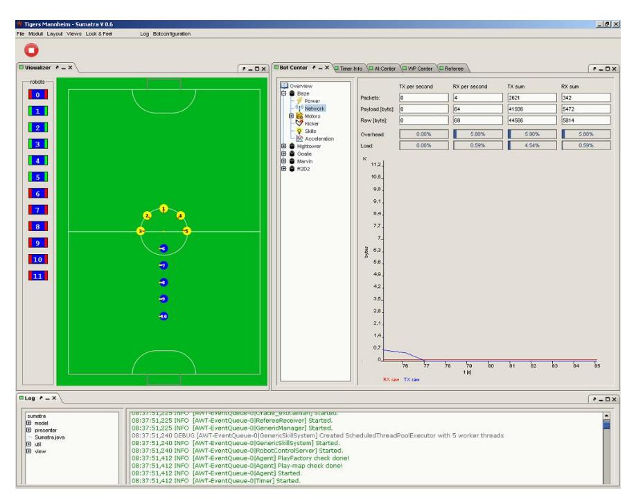
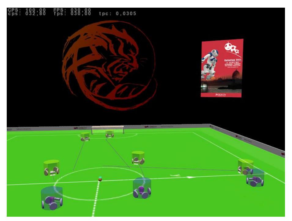
Figure 6 gives an impression of how a simulated SSL match looks like.
4 Prospect
Our qualification video features the system at the version of January 2011. Until July 2011 we will do a lot of improvements. The biggest changes will happen in our electrical design and our AI module. For instance, our shooting-system will be tuned so that we can shoot with 10 m/s. Furthermore we will ensure that our robots are able to react to every possible situation of a common SSL game and improve the precision of the interactions of our robots.
After the tournament in Istanbul all available documentations and source codes will be published on our website, so that other teams can take advantage of our work. Due to the fact that a lot of members of our current team will graduate this year, a new team (which already exists) will take over this project. Besides the "usual" SSL work, they also will take a look on an autonomous referee robot for the SSL.
References
- Zickler, S., Laue, T., Birbach, O., Wongphati, M., Veloso, M.: SSL-vision: The shared vision system for the RoboCup Small Size League. In Baltes, J., Lagoudakis, M.G., Naruse, T., Shiry, S., eds.: RoboCup 2009: Robot Soccer World Cup XIII. Volume 5949 of Lecture Notes in Artificial Intelligence., Springer, Berlin (2010)
- Welch, G., Bishop, G.: An introduction to the Kalman filter. Technical Report TR 95-041, University of North Carolina, Department of Computer Science (1995)
- Sheng, Y., Wu, Y., Wang, W., Guo, C.: Motion Prediction in a high-speed, dynamic environment. http://www.cs.cmu.edu/~shengyu/download/motion_prediction.pdf [Online, accessed 27.02.2011]
- Browning, B., Bowling, M., Veloso, M.: Improbability Filtering for Rejecting False Positives. In Proceedings of 2002 IEEE International Conference on Robotics and Automation, Washington, DC (2002)
- Thrun, S., Burgard, W., Fox, D.: Probabilistic Robotics. The MIT Press, Camebridge, MA (2006) 121-132
- Srisabye, Jirat: Skuba Extended Team Description. http://smallsize.informatik.uni-bremen.de/tdp/etdp2009/small_skuba.pdf [Online, accessed 27.02.2011]
- Bruce, James: Real-Time Motion Planning and Safe Navigation Dynamic Multi-Robot Environments. http://reports-archive.adm.cs.cmu.edu/anon/2006/CMU-CS-06-181.pdf. [Online, accessed 27.02.2011]
- Fowler, Martin: Model-View-Presenter (MVP) http://www.martinfowler.com/eaaDev/uiArchs.html [Online, accessed 27.02.2011]