2011 Team Description Paper: UBC Thunderbots
Andrea Palmer, Alim Jiwa, Steve Huynh, Christopher Head, Jonathan Fraser, Amy Leson, Byron Knoll, Simon Suyadi, Lok Tin Lam, Howard Hu, Kevin Baillie, Tamer Kalla, Stephen Liang, Jason Chang, Matthew Lai, Nazir Zulkafly, Terence Lin, Matthew Parizeau, Victor Hok, Komancy Yu, Victor Tsang, Sandy Lum, Bonnie Lee, Aram Ebtekar, Jordan Balanko, Christian Villar, David Lo, Mayank Kalra, Henry Poon, Amir Bahador Moosavi zadeh
The University of British Columbia, Departments of Mechanical Engineering, Computer Science, Electrical and Computer Engineering, Mining Engineering, and Engineering Physics Program, 2329 West Mall, Vancouver, BC Canada V6T 1Z4
Abstract This paper details the 2011 design of UBC's Small Size League team, to be entered at RoboCup 2011 in Istanbul, Turkey. The main focus of this year was to address the mechanical and electrical weaknesses in the robot from last year, and to build on the existing artificial intelligence of the robot to implement new behaviours and features.
INTRODUCTION
UBC Thunderbots is an interdisciplinary team of undergraduate students at the University of British Columbia. Established in 2006, it pursued its first competitive initiative within the Small Size League at RoboCup 2009. The team also competed in RoboCup 2010 and is currently seeking qualification for RoboCup 2011. Over the years, it has made significant developments of its team of autonomous soccer playing robots. This paper will outline the progress in implementation of the current model of robots, focusing on the mechanical, electrical and software components with particular emphasis on the testing and prototyping of the newly designed multi-directional kicker.
MECHANICAL DESIGN
The maximum dimensions for this year's robot can be found below in Table 1.
Table 1: Maximum Robot Dimensions
| Value | Measurement |
|---|---|
| 148 mm | MAXIMUM HEIGHT |
| 178 mm | MAXIMUM DIAMETER |
| 19% | MAXIMUM BALL COVERAGE |
2.1 Dribbler System (DS11)
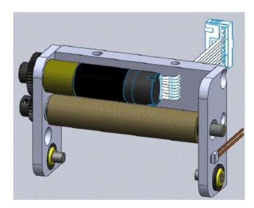
The 2011 dribbler design aims to optimize its performance in ball reception and control through two main changes. First, a height adjustment mechanism for the roller is incorporated such that the vertical contact point with the ball may be modified. This change is crucial to the initial capture of the ball, which directly affects ball control. The height adjustment mechanism increases the flexibility of the robot in adapting to small variations in different turf fields by providing a more suitable contact point on the ball. The most suitable contact point is at an angle 45 degrees to center horizontal plane of the ball so the force is balanced between the horizontal and vertical directions.
Secondly, the dribbler damping mechanism is strengthened by a new rubber layer. In past years, the damping depended on a piece of foam positioned directly towards an incoming ball. The new rubber layer presents a different approach of receiving an incoming ball with a vertical lever system. It allows an opposing force to be applied to the ball over a longer time range, creating a larger impulse on the ball and, thus, more of a dampening effect.
2.2 Multi-Directional Kicker (CK11)
The newly designed multi-directional kicker will have the added function of being able to kick off-center of the robot dribbler plane (the direction the robot faces). It will have the option to place a forward impulse vector nearly 120 degrees from the central axis.
To control the angle of kick, two solenoids are placed side-by-side. Each kicker face is angled 45 degrees inwards from the parallel solenoid. When the kicker face hits the ball off-center, the ball will travel in a direction normal to the angled kicker head, as seen in Figure 2. Having two solenoids with opposite angles allows the variation of the delay between firing and forces the ball to move in a certain direction relative to the direction the robot is facing. The maximum angle and accuracy of the kick depends on the shape of the kicker face and material it is made up of.
The testing mechanism of the CK11 is made up of an inclined test field, sensors, a double solenoid kicker and angled side-boards, as shown in Figure 3. The inclined field and the angled side-boards are designed to guide the ball back to the kicker after each kick. The surface of the test field is covered in felt to simulate competition conditions.
For each test, the trajectory of the kick was tracked using a video camera, which was used to verify the analysis and data collection techniques. This analysis included the maximum error, standard deviation and overall accuracy of each kick. The full testing procedure can be found in [1].
As shown in Table 2, the error for a straight kick is less than 0.6 degree, and 3.6 degrees for a 22 degrees angled kick. The range of kicking is approximately from 0 degrees (straight kick) to 27 degrees with this 45 degrees kicker plates.
Future tests for the CK11 include using 60 degree plates, in order to maximize the range of the kicking angle. The CK11 is expected to be manufactured by March 10, 2011, and implemented in the robots by April, 2011.
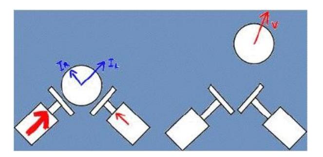
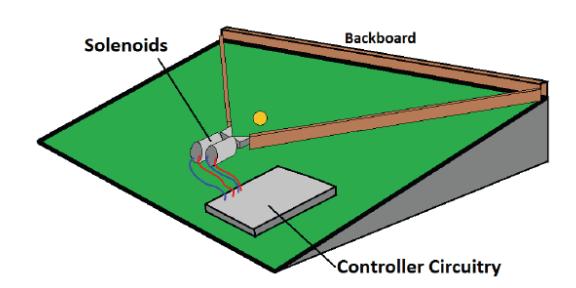
Table 2: CK11 Testing Results
| Angle (degrees) | Max Error (degrees) | Standard Deviation (degrees) |
|---|---|---|
| 0 | 0.60 | 0.38 |
| 11.2 | 1.47 | 0.56 |
| 21.8 | 3.64 | 2.38 |
| 27.1 | 0.93 | 0.47 |
2.3 Drivetrain (W11)
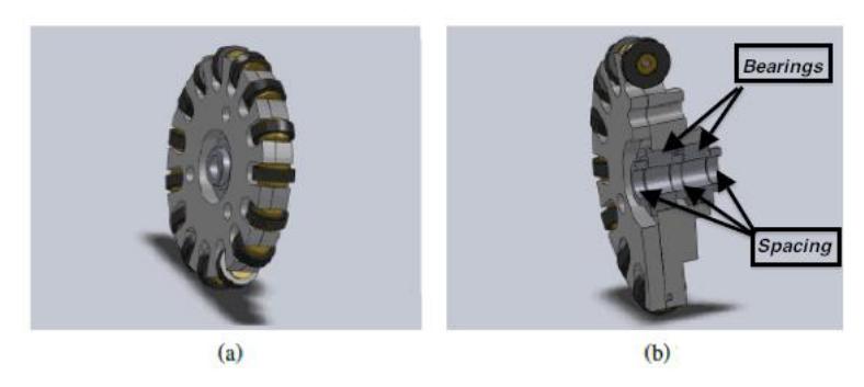
The majority of the drivetrain design for 2011 is identical to the design used in 2010 [2]. However, the main difference is with the wheels: custom manufactured wheels were made for 2011, the design of which was based on the off-the-shelf omni-wheels that were used in 2010. The custom wheels are shown in Figure 4(a).
The aluminum wheels are approximately 2 inches in diameter, with 15 individual brass rollers. The physical dimensions were based on those of the old wheels. The design effort was focused on assembly considerations and designing an effective mounting system that performs well and is easy to implement. The details of the assembly are shown in Figure 4(b).
The drivetrain was designed with all the locating features that required tight tolerances on one part: the thick wheel plate in Figure4(a).
2.4 Solenoid
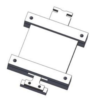
The new solenoid design incorporates pancake solenoid. The solenoids were designed out of delerin, because of its machining capabilities and other characteristics. Considerations were also made for thermal expansion and lower friction values. The new flat solenoid drastically reduces the space occupied by the kicker and chipper device. The number of coil layers and wire gauge were optimized to reduce the cross-sectional area to fit into the solenoid frame. The width of the solenoid plunger, as seen in Figure 5 was reduced, while maintaining the cross-sectional area of the solenoid to maximize space usage against any bending moment issues. The solenoid frame width and length allowed a proportional number of coil windings and wire gauge to achieve the desire solenoid resistance. All the calculations were completed within Matlab, and combined solenoid dimensions and electrical parameters to reach the desired values.
ELECTRONICS
3.1 Communications
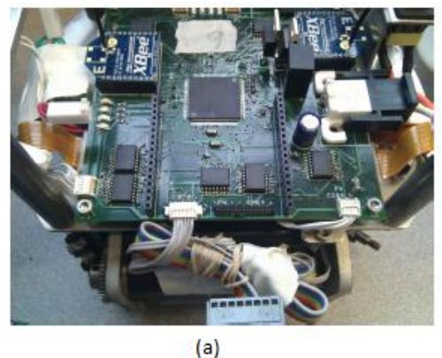
The 2011 communications model significantly improved the implementation of communication devices. In 2010, communication relied on a single XBee 802.15.4 module, from Digi International, for uploading and downloading data with the host controller [2]. A two-way flow of data occupying the same channel led to unwanted channel contention. This year, 2 XBee's were implemented: one for sending data and one for receiving. This improved real-time positioning of the robots by easing the channel contention. The XBee's are shown in Figure 6 (a).
3.2 Power Generation
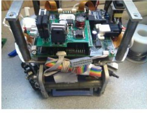
The boost converter subsystem was redesigned this year, with a focus on simplicity and reliability. The purpose of the boost converter is to amplify voltage to 230V and will be used for kicking and chipping. In 2010, this subsystem consisted of a flyback converter embedded on the main circuit board [2]. Being embedded, the design was unnecessarily complex and unreliable. This year, the subsystem was redesigned as a separate board that mounts on top of the main board. The simplicity of this improved design proved to be much more reliable than its ancestor. The mounted boost converter is shown in Figure 6 (b).
3.3 Packed Boards
Due to the high level of concentration of electronic elements on the main circuit board, the boards we changed from a 2-layered PCB to a 4-layered PCB. A 4-layer configuration provides a full power plane that stabilizes unwanted voltage fluctuations in the circuit.
3.4 Motor Control
A final improvement made on the circuit networks is the subsystem that controls the brushless DC motor from Maxon Motors. Last year, all commutation for the motors was done by MC33035 motor controller chips [2]. All five MC33035 and their phasedriver MOSFETs are collected on a "motor controller board". Since an FPGA was already present in this year's design, the directed motor control functions have been relocated from the MC33035's to the Xilinx XC3S50A FPGA. This change enabled better controls of the motor and simplified circuit board design.
SOFTWARE
4.1 Skills Tactics Plays (STP)
The main high-level decision making model used is the STP model, developed by CM-Dragons in 2003 [4].
The STP model is used to manage multiple robots in a challenging adversarial environment. In this environment, the decision making model handle short dynamic events, while simultaneously trying to achieve long-term objectives. STP is composed of Skills, for executions of low-level actions, such as a simple move or kick; Tactics, that determine the skills for use by the robots; and Plays, which assign roles for the robots to execute tactics [3]. The hierarchical architecture within the STP model allows for dynamic quick response and coordinated control. The team will be able to achieve long-term goals in a highly coordinated manner, and, similarly, react to dynamic events initiated by the enemy. At the top of the robot control hierarchy, the STP model makes decisions
as to where the robots are destined, and the lower-levels of the hierarchy handle the path that each of the robots should take to get to the determined destination. Figure 7 shows the cycle of the STP model.
4.2 Controller
The robot-controller level of the AI takes a set of points defining a path as an input. Each point is also associated with a desired orientation and a desired time of arrival.
The robot controller outputs velocities for each of the robot's four wheels.
The parameter tuning is done using a stochastic local search that optimizes an objective function, which is defined by the time it takes a robot to complete a movement benchmark. The movement benchmark involves moving to, and stopping at, a set of points on the field. The movement benchmark can either be simulated or run on a real field.
There have been several robot controllers implemented and they can be selected via a drop-down menu in the AI's graphical client. Currently, the best performing robot controller uses "fuzzy logic": it takes weighted combinations of a variety of factors (such as robot velocity, distance to destination, etc.) to determine the desired acceleration. The automated parameter tuning allows the "fuzzy controller" to adjust to changes in the physical robot design and to changes in the field surface material.
4.3 Navigator
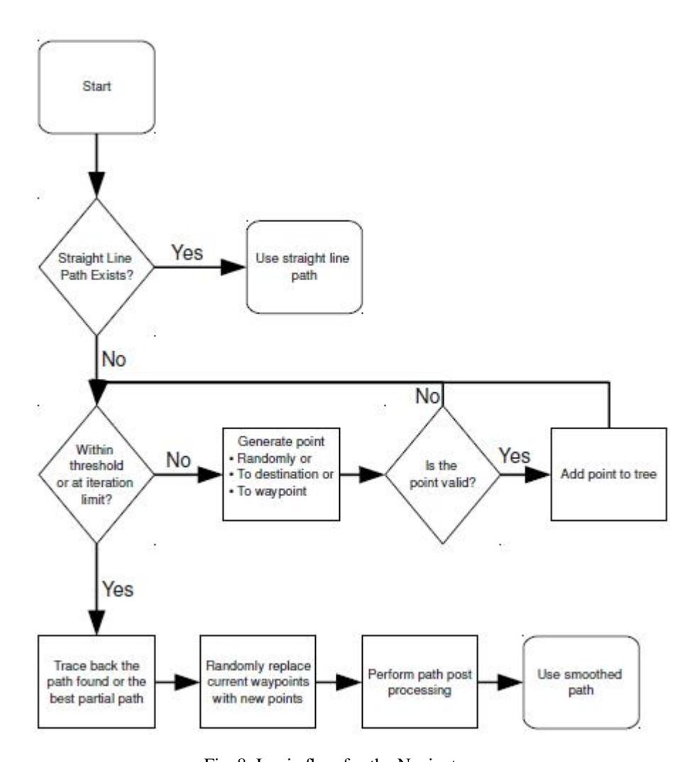
The robot navigation uses a rapidly exploring random tree algorithm. The logical flow algorithm of the navigator is shown in Figure 8.
First, it attempts to go in a straight line to the destination, and check if there are obstacles in the way. If there is something in the way then, for a fixed number of iterations and starting with the the robot's current location, it attempts to generate a path to the destination avoiding all obstacles. Initially, a tree is created with only a root node at the current location. Randomly, a point in the chosen direction (or towards the destination) is selected. If this point is in a valid location, it is added to the nearest point in the tree. This is repeated until the robot reaches a predefined iteration limit or it receives a point that is within some threshold to the goal location. If no path is found in the iteration limit, then the robot is given the best partial path to the destination.
To improve upon this and to minimize oscillation between generated paths, a set of waypoints on each successfully generated path is stored. The waypoints are randomly replaced on each successful generation, and are randomly chosen when selecting a point to attempt to expand to. In the case when the robot is attempting to manoeuver around another robot, the waypoints help to consistently generate paths to navigate around the robot in the same direction. It was found that before using waypoints, the navigator would often generate paths in one direction and the exact opposite with about equal probability.
The paths generated by this algorithm are not very smooth, so post-processing is performed in order to smooth out the path so that the robot can follow it with more ease. Once a list of points has been obtained from the algorithm, the line paths from the starting point incrementally increase until an invalid value is reached. Then, starting from this point, the process is repeated in order to minimize the number of points in the path.
4.4 Predictor
In order to deal with the challenges of input delay and uncertain measurements that occur in real-time, a Kalman filter was implemented. The filter is based on a dynamic statistical model, which allows the future state of the robots to be predicted based on past states and control inputs. The prediction algorithm extrapolates from past estimates of position, velocity, orientation and angular velocity to arrive at an estimate of its present state. This prediction is combined with the latest measurements to produce a more reliable result that varies smoothly with time. Each estimate is weighted by its uncertainty and represented in the form of a covariance matrix, so that the best estimates have the greatest influence on the output. Thus, while an outdated measurement will gradually lose its influence as new data comes in, a single "noisy" measurement that conflicts with predictions and past data will not compromise the AI systems, which rely on these estimates.
Acknowledgements
We'd like to thank the Faculty of Applied Science; the departments of Mechanical Engineering, Mining Engineering, Electrical Engineering, Engineering Physics, and Computer Science; and the University of British Columbia for their continued support. We'd also like to thank all our sponsors for their generous contributions to undergraduate student learning and research.
References
- DeLuca, J., Kalla, T., Li, A., Perttula, M., Wilkie, J. Critical Function Prototype Report for MECH 458 Thunderbots Manipulator, 2010.
- Jiwa, A., Knoll, B., Head, C., Hu, H., Fraser, J., Serion, J., Baillie, K., Lam, LT. 2010 Team Description Paper: UBC Thunderbots, 2010.
- Browning, B., Bruce, J., Bowling, M., Veloso, M. STP: Skills, tactics and plays for multirobot control in adversarial environments, 2004.
- Browning, B., Bruce, J., Bowling, M., Veloso, M. CMDragons03 Team Description Paper, 2003.