KIKS 2012 Extended Team Description
Kenji Inukai, Yasuyuki Iwauchi, Shoma Mizutani, Takaya Asakura, Ryu Goto, Masato Watanabe, Toko Sugiura
Toyota National College of Technology, Department of Electrical and Electronic engineering, 2-1 Eisei-cho, Toyota Aichi, 471-8525, Japan
http://www.ee.toyota-ct.ac.jp/~masa/2012/kiks2.htm
Abstract This paper presents a detailed description of KIKS in addition to the team description paper of small size league in RoboCup 2012. Our robots and systems are designed under the RoboCup 2012 rules in order to participate in the RoboCup competition. The major improvements in this year are the enhancement of the performance and robustness of wheels, dribbling device and electrical circuit.
Keywords: RoboCup, small-size league, engineering education, global vision
1. Introduction
Main purpose of our participation to the RoboCup world competition is confirmation and evaluation of the results of the PBL (Project Based Learning) experiments. The creative minds of students are educated using the robot contest held in our department every year. In the RoboCup world competition, our team has continuously participated since 2004. We came in the top 4 in Singapore and Istanbul. Since we are aiming for the higher position in this year, further improvements has been done.
Robot's performance was improved by replacing to brushless DC (BLDC) motor at last year. But, we found the durability problems related to wheels through the competition. The dribble device was also in poor condition. So, we redesigned whole mechanical parts, and especially tried to replace the parts of wheel and dribbling device.
The main topics of developed system in 2012 are following terms,
- Improvement of the wheels
- Improvement of the dribbling device
- Improvement of the circuit for BLDC motors and high voltage charger
2. Hardware of the robot
The Overview of 2012 model is shown in Fig. 1. The basic configuration of a 2012 model is common with the 2011 version. It has been made the improvement to the dribbling device, chip kick device and bearing of wheel in 2012 model.
We made the omnidirectional wheels ourselves. We also use the brushless motors (maxon EC45 flat) for the driving motor, as in many teams. For the dribbling device, we also use the brushless motor (maxon EC-max22). Each robot has three solenoids. One is for straight kick and the other two are for chip kick. The robot is able to shoot the ball at a speed of 10[m/s], however, it is down to 8[m/s] to keep to the regulations. The height of the robot is 148[mm] and diameter is 178[mm]. The specification of the robot is summarized in Table 1.
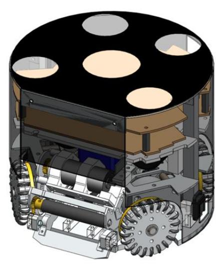
Table 1. Specification of the 2012 version
| 2012 version | |
|---|---|
| Weight | 2.3kg |
| Main material | Aluminum alloy |
| Driving motor | maxon EC45flat (30Watt) |
| Gear ratio | 3.6 : 1 |
| Wheel diameter | 56mm |
| Number of solenoids | Straight kick: 1 Chip kick: 2 |
| Straight kick power | Ball speed of 8[m/s] |
| Chip kick power | 3.0m away from robot |
2.1 Robustness improvement of the wheel
In RoboCup2011, many problems were occurred by hard collision in play. Especially, the wheels were badly damaged to the flange of the bearing. Figure 2 shows the bearing used in the wheel. (a) and (b) show the normal and broken one, respectively. More than 20 bearings were damaged in the game of last year. This fact may be caused a serious problem in rule of 2012. Because the direct free-kick will award to opposite team, in case the parts of our robots fall on the field and it results in a disadvantage of opposite team. Anyway, we need to solve quickly this problem.
Figure 3 (a) and (b) show the 2011 and 2012 version, respectively. In 2011 version, the external thrusting forces give the damage to flange of the bearing. Therefore, in 2012 version, we replace the bearing with the larger bearing with no flange to counter the influence of external forces. Incidentally, the cost was also decreased. Now we're examining the many facets for the robustness of this new wheel. A part of experimental results is shown in Table 2. An aluminum solid of 2.4kg is fallen down perpendicularly from the position of 50cm height to the center of the side-face in wheel. We verified the practical effectiveness by evaluation of repeat count until crash. As a result, it seems fairly good performance.
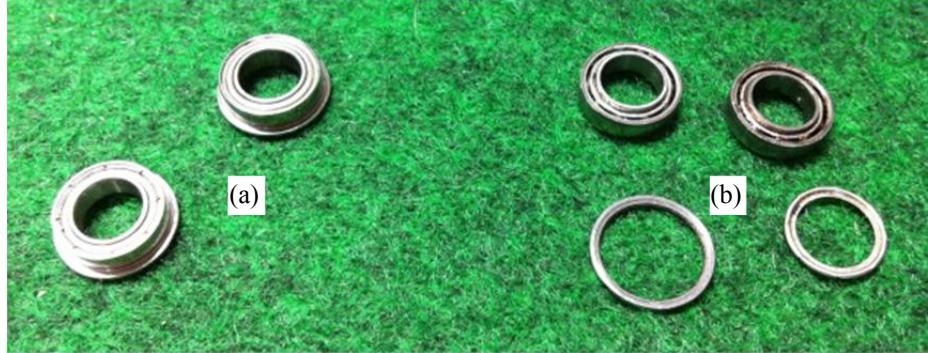
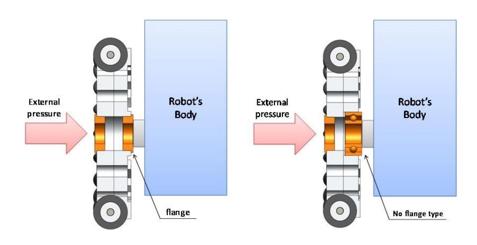
Table 2. Confirmation of the durability of new wheel
| Repeat count until crash | |
|---|---|
| 2011 version | 4 |
| 2012 version | over 10 |
2.2 Optimization of dribbling device
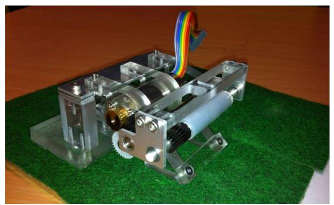
In 2011, we changed the dribbling brush motor into brushless one (maxon ECmax22) to give the powerful backspin to the ball. But, in current mechanism of dribbling device, it is occurred the vibrational oscillation from time to time when the ball is rotated at high speed. The failure that was not able to hold a ball resulted from the vibration. It means that it is not necessary with high speed of dribbling device. So, we tried to optimize the parameters for the dribbling device by using the Solid Works Motion as an aid to the analysis. We investigated about the suction force of the dribbling device. It is evaluated by the height of the roller and its diameter as the parameter. When the vibration is occurred, there is also vibrational oscillation in electrical current of circuit. So, we fabricated the experimental device to find the optimum value mentioned above. Experimental device to obtain electrical current and suction force is shown in Fig. 4.
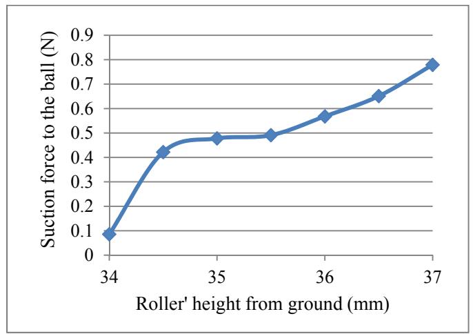
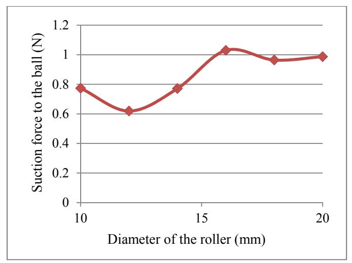
Figure 5 shows the relationship between suction force to the ball and the roller's height in dribbling device. In Fig. 5 the suction force to the ball is increasing as increase of roller's height. On the other hand, the suction force is not changed much under the condition that the diameter of the roller increases doubly, as shown in Fig. 6. Summarizing the experimental results in limited condition, the diameter of the roller does not significantly affect to the suction force, and it is found that the roller's height from ground is more important factor.
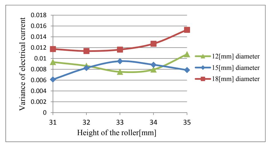
Figure 7 shows the relationship between the variance of the electrical current and the roller height. From Fig. 7, it is predicted that the variance of electrical current will be getting worse if the diameter of the roller is over 18mm long. Therefore, we define the roller's diameter and height from ground on the basis of these results.
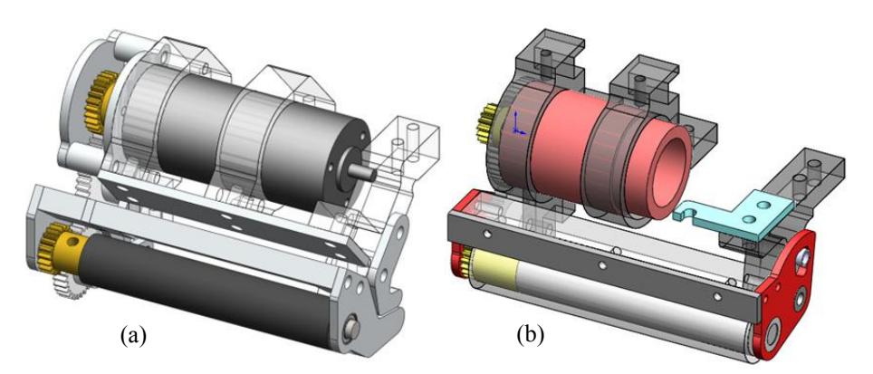
The dribbling devices are shown in Fig. 8. The 2012 model is developed based on the 2010 version. The 2012 model in Fig. 8 (a) is different from surface material and the diameter of roller compared with 2010 version in Fig. 8 (b). That is, silicone rubber was changed into polyurethane rubber, and the diameter of 10.5mm with A5056 material was changed into that of 4mm with SUS304 in 2012 model.
3. Electrical design
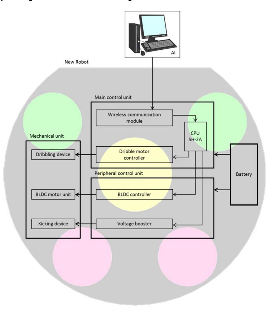
The electronic circuit of KIKS is mostly same as last year. The new electronic circuits consist of two main boards shown in Fig. 9. They are main control unit and peripheral control unit. The main control unit includes the main CPU, power supply circuit, wireless communication module, ball detecting circuit and dribbling motor controller. The peripheral control unit includes motor driver and voltage booster. The major changes are motor driver and voltage booster circuit.
3.1 Main Control unit
This unit includes the circuit for detecting a ball, power supply circuit and wireless communication module. The SH7262 (SH-2A series of Renesas) is used for a main CPU that communicate each PIC for the peripheral controllers, such as BLDC controller, voltage booster circuit etc. The CPU runs 144MHz (345MIPS) and has 1MB RAM. Its performance is enough to achieve the precise control of the robot.
3.2 Wireless communication system
We have used the Digi's XBee module for communication system between host PC and each robot. The wireless communication's frequency is 2.4GHz band. The XBee module is able to communicate faster than conventional wireless module. It is possible to communicate up to 115200bps.
3.3 BLDC motor driver
An each robot has four BLDC motor driver circuits for omnidirectional moving. The MCU of motor driver is dsPIC30F4011. This circuit is added electrical current sensing system. So, it is possible to control torque of each motor. The motor speed of the robot is controlled by PI speed control in MCU. This circuit is also used for dribbling motor controller.
3.4 Voltage booster circuit
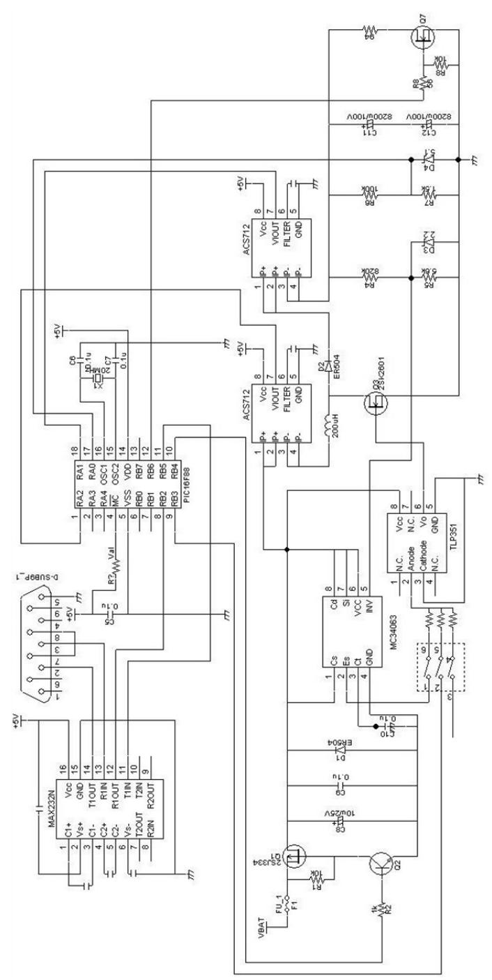
The DC-DC converter is used for the solenoid to boost up the voltage. The input voltage of 16V is converted to 200V output. This chopper circuit is controlled by PIC in each robot. In the kicking device, the output voltage of 200V is charged in 4100μF capacitor.
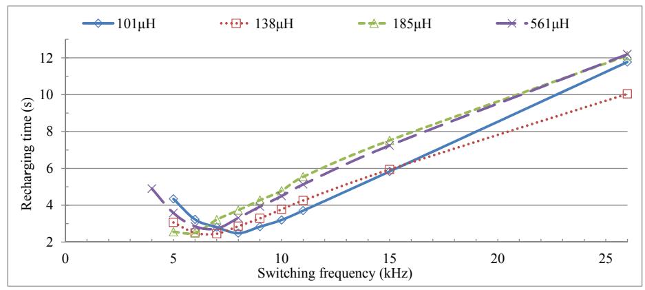
In last year the time to charge up to 200V from 16V is 5 seconds. To shorten the charging time, we try to optimize the coil inductance and switching frequency. We made experimental circuit to evaluate that parameter. The electrical circuit and result are shown in Fig. 10 and Fig. 11, respectively. In Fig. 11, in the case of capacitor of 4100μF and duty ratio of 80%, it found recharging time was decrease to 2.46 seconds. Thus, we used the coil with 185μH and applied switching frequency of 6kHz.
4. Software design
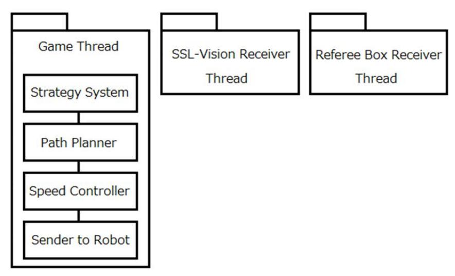
The image of AI system is shown in Fig. 12. Software design is mostly same with last year, however, based on the modification of the rule, AI system was done minor change. The overall software architecture is shown in Fig. 13. The software consists of three threads, i.e., the Game Thread, the SSL-Vision Receiver Thread and the Referee Box Receiver Thread. Moreover, the Game Thread includes some modules. The role of each module is described in detail below.
4.1 Strategy system
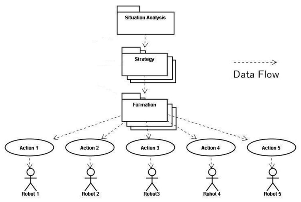
Strategy system is improved from last year. The architecture of new strategy system is illustrated in Fig. 14. The strategy system consists of four modules called "Situation Analysis", "Strategy", "Formation" and "Action". They are defined as following.
4.1.1 Situation Analysis module
This module is located at top level in strategy system. This module plays the role of analysis about the game situation from both position of the ball and robots on the field and generation of the trial instruction command.
4.1.2 Strategy module
This module is located at below level of Situation Analysis module. The role of this module is to select the optimal next Formation module from result of analyzing. For example, when the result of analysis is "Indirect Free Kick of Own team", the Strategy module will select the "Indirect Kick Formation module". On the other hand, when the result of analysis is "Need to Defense", the Strategy module will select the "Defense Formation module". Since the Strategy module has many strategy patterns, it will be able to select the optimal Strategy module corresponding to the game situation.
4.1.3 Formation module
This module is located at below level of Strategy module. This module plays the role to decide Action module which should be performed by each robot in next.
4.1.4 Action module
This module is located at the bottom level in strategy system. The role of this module is to command the specific operations to each robot. The "Direct Shoot Action" for instance, is commanded to the robot for kicking a ball. Alternatively, the "Wall Defense Action" means the robots move to the position defending the goal.
4.2 Path Planner
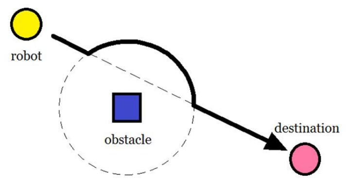
Destination of each robot is determined by the Strategy system. Path Planner is the module to generate a route that avoids defense area and the other robots. The method of generating route is followings. First, it generates the linear route that connects the current position and destination. Next, it checks all of obstacle position. If there is obstacle on the route already generated, it is changed the route using an arc formed with constant radius at around the obstacle as shown in Fig. 15. Then, if there is still other obstacle on the route, the radius is increased until that can be avoiding obstacle.
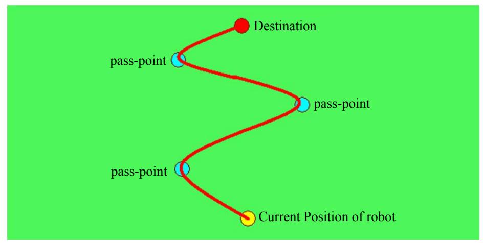
In previous one, it was not able to generate a path on the condition that goes through middle-point between current position and destination. So, we improved that to be able to go through for the arbitral point. In present one, it can make a path taking account of pass-points as shown in Fig. 16.
4.3 Speed Controller
Speed Controller calculates the data related velocity to send the robot based on current speed of the robot and the generated route. Speed Controller has several types. Optimal type of the controller is selected corresponding to the role of robot.
Speed Controller was also improved with modification of Path Planner. In present one, the coordination of pass-points is used as the information for generation of robot's velocity, angle and position etc.
4.4 Sender to robot
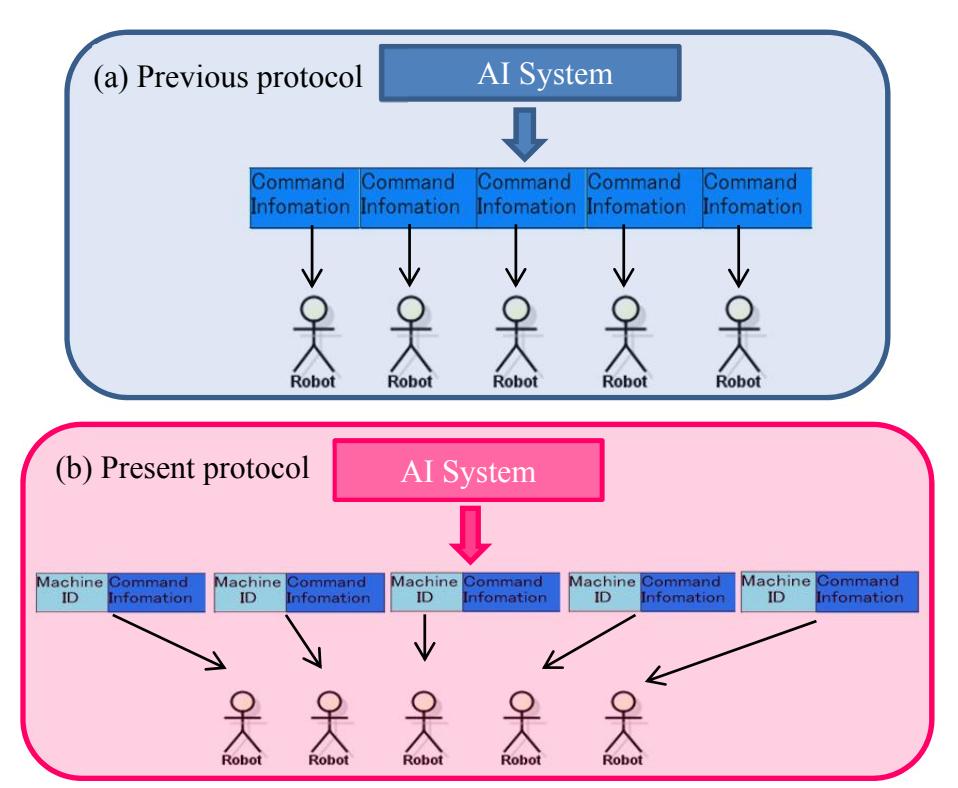
This module is used for sending the data to robot. In this year, we improved the protocol to send the data. Figure 17 show the sender's protocol of AI system. While the same command informations are sent to 5 robots simultaneosuly and each robot recognized the necessary information from sent data by themselves in previous system in Fig. 17(a), in present protocol in Fig. 17(b), the command information with unique ID number for each robot is sent. Thus, the information for one robot is sent at once using their own inherent ID number. If there is accident for the robot in game, we can change quickly and simply the robot with unique ID number added to command information in present protocol. As the results, there is no need to worry, for example, about working doubly as keeper's robot by using incorrect robot's number. Moreover, There is no limitation for number of the robots in present protocol.
4.5 Control of kicking power
According to the 2012 rule, there is limitation of 8m/s for a ball's speed. In previous AI system, it was not able to control the kicking power with precise adjustment. It was only four steps. If there was necessary to make drastic revision of kicking power, we had to rewriting the PIC inside the robot. Thus, it became possible to change the kicking power in 255 steps on AI system. As the results, it became possible to kick the ball with accuracy and there is also no need to rewrite the PIC inside the robot.
4.6 Simulation System
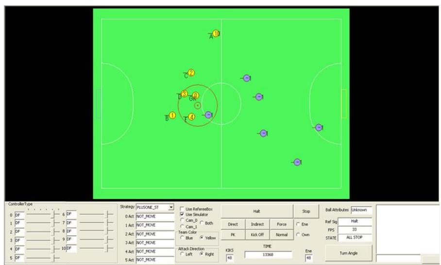
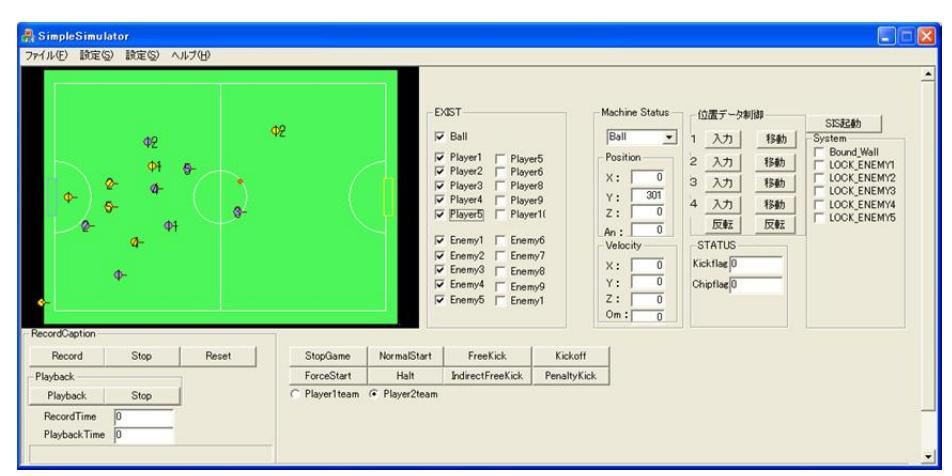
In recent year, there is little difference amang the hardware in SSL teams. Therefore, it is very important the performance of software. We have to construct more excellent AI system in short period and effectively. Up to now, we have used the simulator that was given the minimum required function to debug AI system. Thus, we improved that to develop the AI system efficiently in addition of many function as shown in Fig. 18. Especially, we introduce the recording system of game, referee system instead of RefereeBox, and AI system for Enemy. This system give real game situation to AI system. As a results, we don't have to use real robot in many times, and can construct and evaluate the strategy in short time.
5. Conclusions
Our robots have been continuously improving in every year. As the results, the durability and the performance of robots are getting better than previous year. Especially, the improvements of dribbling device are effective for construction of numerous strategies and pass plays.
We hope that our robots will perform better in this coming competition.
References
[1] RoboCup Small Size League official rules