MRL Extended Team Description 2012
Aras Adhami-Mirhosseini, Omid Bakhshande Babersad, Hamidreza Jamaati-tafti, Siavash Asadi-Dastjerdi, Sajjad ziyadloo, Amin Ganjali-Poudeh
Islamic Azad University of Qazvin, Electrical Engineering and Computer Science Department, Mechatronics Research Lab, Qazvin, Iran
Abstract This year small size soccer environment, have changed significantly. Increasing players to six robots and decreasing the maximum kick speed, results in the more dynamic and strategic games. With this attitude, it seems that teams are supposed to restructure their mechanical, electrical and AI parts to adapt with the new condition. MRL small size soccer team with more than four years' experience in different international competitions, is planning to complete all requirements to reach at his highest level when participates in 2012 world games. After attaining acceptable performance to reach the third place in 2010 and 2011 competitions, MRL team are scheduled to modify and change different parts. The first step of this year attempts, focuses on redesigning of some important parts of the robots' mechanic to increase the total weight and increase the reliability. The second task is an optimization on the direct kicker system to meet the new limits with as light as possible system. Software redesigning and improvements are the last and important step at this year research schedule. Improvement of the control and estimation/prediction are minor modifications at this year. Finalizing our debugging tools like 3D simulator, physical and non-physical simulators in this year aided us to evaluate whole of the system software from low level control to high level strategies. First rank at Iran open 2012, verifies the achievements in the way of fast and reliable robots, accurate motion, reliable defending and flexible attacking strategies. Besides, it is observed that there are still some problems in different areas, e.g. motion control, dribbling system and strategies, which should be solved till the time of RoboCup 2012.
1 Introduction
MRL team started working on small size robot From 2008 and after three years we could qualified to be in semifinal round and attaining the third place in 2010 and 2011 RoboCups. This means that our last year's plan was achieved. The main problem in MRL robots in 2011 competitions was its unreliable behavior. Mainly, slow and inaccurate motion together with software problems gave opportunities to the opponents to score. Our main target in this year plan is resolving the motion problem by modification on the mechanical and electrical structure and redesigning the AI mechanism.
Some requirements to reach the fast and accurate motion are satisfied with hardware restructuring. New methods in control are designed using reliability of the new hardware that is gained by evolution of software tools like online debugging tools and simulator, for more details see [1]. Iran open 2012 was an opportunity to evaluate our new contributions. Although, the modified robots are much faster than the old ones, there are still some problems that should be solved to reach reliable robots. Being the first team in these competitions shows our progress.
This paper is organized as follows: Firstly, our new software architecture including game planner, strategy manger and … are described in section 2. The modified electrical design and optimized kicking system, is explained in section 3. Description of mechanical configuration modification for the newly designed robot which elevates the capabilities of the robots' smooth and reliable motion is the subject of section 4. Finally, our modification on the motion control which has a key role in robot performance is the subject of the last section. Further research on this topic to reach the perfect motion control is under investigation too.
2 Software
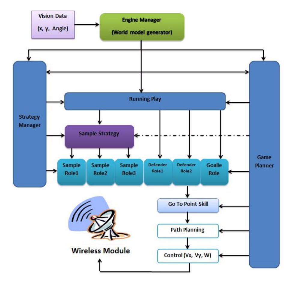
In this part the software main objects are presented. It is shown that how our new architecture provides us a safe and flexible game. In this year MRL software team has changed the AI structure and built up a new architecture. The new game planner as the core unit for dynamic play and strategy manager layer are introduced in this section. After these major changes, minor modifications on the other parts like visualizing systems are presented. Following paragraph, sketch an overview to the MRL software modules and their connections.
The software system is consisted of two modules, AI and Visualizer. The AI module has three sub-modules being executed parallel with each other: Planner, STP Software, and Strategy Manager. The planner is responsible for sending all the required information to each section. The Visualizer module has to visualize each of these sub-modules and the corresponding inputs and outputs. The visualizer also provides an interface for online debugging of the hardware. Considering the vision subsystem as an independent module, the merger and tracker system merges the vision data and tracks the objects and estimates the world model by Kalman filtering of the system delay. Figure 1 displays the relations between different parts. In this diagram, an instance of a play with its hierarchy to manage other required modules are depicted.
The system simulator is placed between inputs and outputs and simulates the entire environment's behavior and features. It also gets the simulated data of SSL Vision as an input and proceeds with the simulation. This year we add a new feature to our simulator that uses the kinematic modeling of robot motions.
In the following subsections we introduce each layer of the AI mechanism. Note that, the arrangement of the introduced layers is to increase tractability.
2.1 Role assignment
MRL AI architecture is based on the STP platform introduced by James Bruce [2]. Our game strategy aims at dynamic assignment of some pre-defined roles to the robots in the field. The dynamic assignment tries to assign the best role to each robot at each time frame, making the strategy more flexible to the new events and positions in the field.
Dynamic role assignment is much more complex than static role matching. Therefore a new role matching algorithm was required to effectively assign roles to the robots at each time frame. Our algorithm addresses the role matching problem by considering two different states for each robot at each time frame; whether it stays at its previous role or switches to a new, overall more efficient role. The algorithm requires taking into account the set of all robots and all roles and should select the highest overall priority for robot-role matching. A cost function for each role has been designed and each frame cost of a role for a specific robot has been calculated. We map the intended problem into the maximum matching in a bipartite graph.
2.2 Strategy management
In this year we introduce a new layer of MRL AI hierarchy, the Strategy Layer. In the strategy layer, the AI system learns to select the best game strategy for some specific time frames. Each strategy is a heuristic game playing for certain number of attendees. "Field region", "game status" and "minimum score to be activated" are parameters pertaining to each strategy. For instance, Sweep and Kick strategy with three attendees works the best in the middle of the field is activated after score one, and requires "Indirect Free Kick" game status. If all the four parameters are satisfied, the strategy becomes "applicable" at certain time frame. We model each strategy as a Finite State Machine (FSM). Consecutive states of strategy's FSM indicate the chain of actions required to be performed in that strategy. The transition conditions between states reflect the prerequisite conditions for the actions. The FSM has got an initial state with which the "applicability" is verified. It also has got Trap and Finish states indicating "failed" and "successful" ending of the strategy, respectively. A dynamic score is designated for each strategy. After completion of each strategy (either failed or successful), the strategy score is updated.
Strategy manager operates as the highest component of the Strategy Layer. This component is responsible for selecting the best strategy at each time frame. The strategy manager has got three different selection policies:
- Random Selection: The manager randomly selects one of the applicable strategies.
- Higher Score with a Probability of Random Selection: The manager tends to select the strategy with the highest score as of now, trying to apply the best strategy which has proved to have the best performance. Also, for the sake of giving the chance to some lower scored strategies to make progress, the manager randomly selects a strategy with probability of P.
- Weighted Random Selection: The manager randomly selects one of the strategies, each of which has a weight corresponding to the probability to be selected.
The Strategy Manager selects one of the applicable strategies in one of the three mentioned ways and the attendee robots are assigned roles for performing the strategy. When the strategy traps or successfully ends, robots are reassigned roles for the normal play. The strategy layer helps us to avoid a share data or blackboard for agents. Therefore we can design a cooperative game of agents, dynamically.
2.3 Game planner
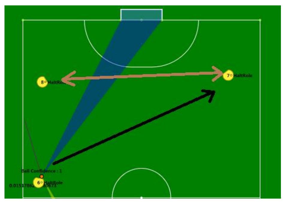
Game Planner is a part of our AI, which provides the information about the game. We use that information to choose good strategies for attacking and defending. In fact Game Planner analyzes the game to use in other part of the AI mechanism. So the accuracy and reliability of the processed information is very vital and should be comprehensive. Thus we need exact and complicated calculations to obtain it. Computational complexity and parallel essence of algorithms are used in the planner, make us to use "GPU programming" to speed up the calculations. There are many interfaces that can be used to do that, e.g. OpenAcc, OpenCL, Direct Compute and Cuda. Among them, "Cuda" is using C programming language that make it more suitable in our task. NVidia has created and optimized "Cuda" only for GPUs produced by itself. We use Cuda 4.1 and a GTX 580 graphic card. Following, we describe Game Planner most important parts.
2.3.1 Prioritizing opponents robots
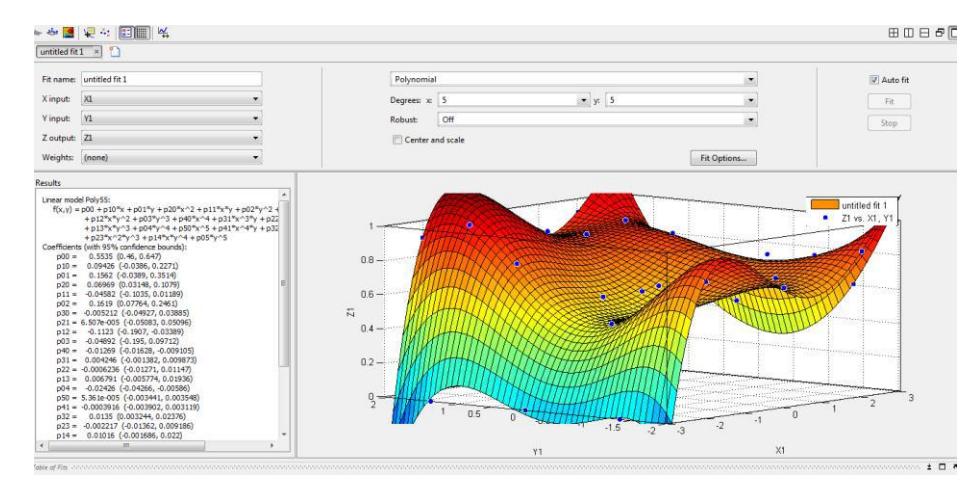
This part plays the main role in defensive tactics. In each frame we calculate a score between 0 and 1 for each opponent robot. This score shows each robot's importance in opponent's offensive movements. This is very important for us, because if we give each robot a proper score we can cover their attack with a proper defense strategy. On the other hand, because of the various attacking strategies used by different teams, covering all possible game conditions needs a lot of parameters and that raises the chance of mistakes and creates scoring chances for the opponent. Collecting all these parameters and connecting them together is a very hard or even impossible task. To do that, we have divided scoring to two parts: online and offline calculations. In offline mode by preparing a lot of samples and scoring in different situations of the game, we create a function of initial conditions that have a static nature like location of the most important robot (the robot owning the ball) and location of other robots and … . This function assigns each robot a score. In the online mode, some important parameters like direction and speed of the ball and robots, time it takes for each robot to reach the ball and ... are used to calculate the score. Then we give the results as input to the function that is calculated in offline mode. Then the results of the online and offline calculations are combined to get the final score.
2.3.2 Regioning:
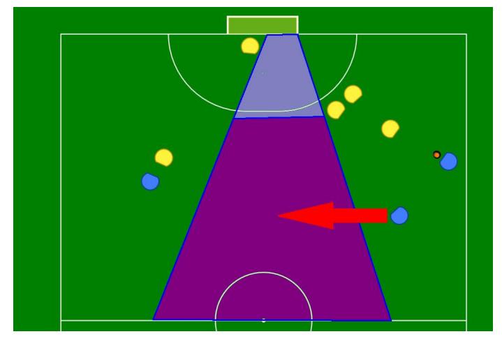
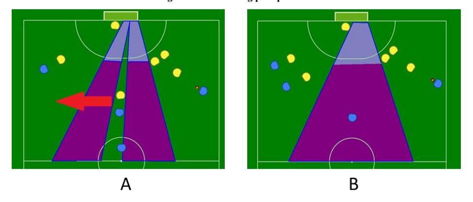
Another important part is regioning. In this part using different algorithms we recognize empty spaces of the field. And we use those spaces to choose a good strategy. Also using this part in different times of the game executable strategies are suggested too strategy manager. In recognizing empty spaces of the field we use the idea of light being blocked by objects in field. We consider light sources on certain points on the field .The shadows created by objects on field are analyzed for each light source. We combine those using parallel algorithms to divide the field into regions. These regions are mostly used to find the best spot for direct or air passes. And also with analyzing these regions online and changes of their area over time, we improve our strategies and off ball movements. For example with off ball movements we can adjust important regions in a way that certain strategies can be executed.
2.2. Online internal debugging
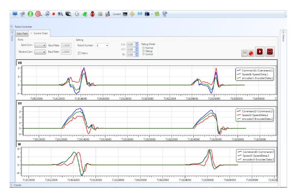
As stated before, to debug onboard control modules such as wheels' speed and controller parameters a comprehensive debugging tool is required. Simultaneous investigation of the commanded and the robot velocities (computed via vision and encoder data) is desired. Using this new approach we can easily debug and analyze our PID controller, wireless module data or any of our internal components. We've designed an online link between our microprocessor and AI systems in order to debug and maintain all controllers and speed problems easily and in a time optimal fashion. Figure 6. shows our internal debugger graphical interface. If the desired velocity and the robot speed measured by vision are similar, the control performance will be suitable.
Previously, we had a unique configuration states for all of the robots without considering differences between them. This year, we have embedded a sub-section to our AI system which stores specific properties of each robot which later would be used for system's calibrations. These properties include controlling issues, kick speed or any kind of configuration parameters.
2.3. Applying Reinforcement Learning
Temporal Difference learning, first introduced by Samuel [3] and later extended and formalized by Sutton [4] in his TD() algorithm, is an elegant technique for approximating the expected long term future cost (or cost-to-go) of a stochastic dynamical system as a function of the current state. The mapping from states to future cost is implemented by a parameterized function approximator such as a neural network. The parameters are updated online after each state transition, or possibly in batch updates after several state transitions. The goal of the algorithm is to improve the cost estimations as the number of the observed state transitions and the associated costs increments. We find out that this elegant technique could be useful during online dynamic game. The pseudo code of TD is illustrated in Fig.6.
Initialize V(s) arbitrarily,  to the policy to be evaluated
Repeat (for each episode):
      Initialize s
      Repeat (for each step of episode):
               a ← action given by  for s
               Take action a, observe reward, r, and next state, s'
               V(s) ← V(s) +  [ r +  V(s') - V(s) ]
               s ← s'
      until s is terminal
Fig. 6. Tabular TD(0) for estimating V .
Therefore, one can benefit from this robust method in low and high level of decision making e.g. in making decision about direction of kick in non-static balls. When the robot pass the ball to another one, the speed of moving ball in the vicinity of the second robot interferes in the direction of final kick to the target. To control this problem, Temporal Difference could be applied.
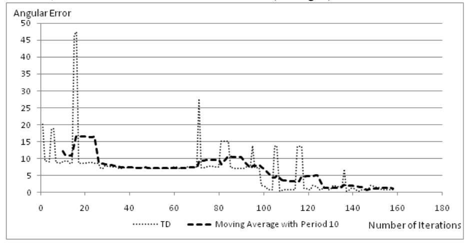
Rewards of kicks in the vicinity of the target are calculated and learning loop is triggered after each kick. To evaluate the method performance, at first it was tested on our 3D simulator. The results of this reinforcement learning approach show that after several runs, the correct direction will be determined (see Fig. 7).
2.2. High level Analyzer
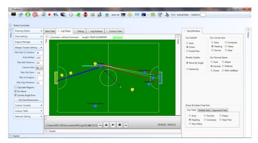
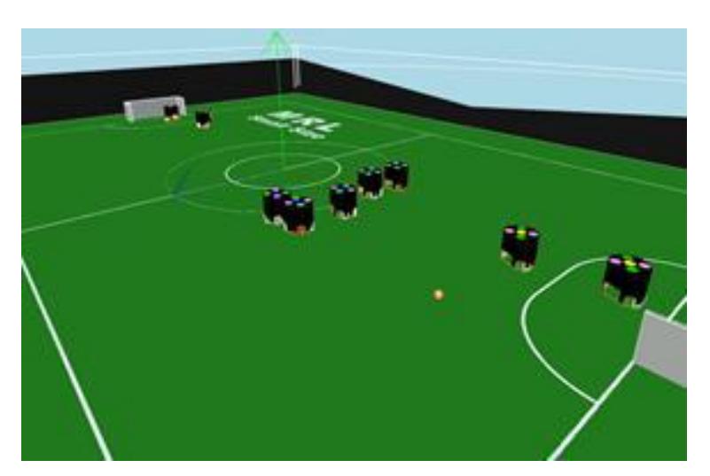
One of the most significant variations we have made to our MRL2011 team is the implementation of a new decision making layer as a high-level analyser (Fig. 8). Log files from SSL Vision of all MRL games should be recorded during a game. The final stage is the extraction of the opponent team strategies and finding the best tactic to cope with it. Although, it is too far from implementation, the preliminary steps are under construction. Strategy model consists of different parameters such as the number of robots in each position e.g. defence robots, attackers and free robots. Our goal is distinguishing the best feasible strategy from these models dynamically. For instance, if the opponent team is attacking with one "attacker", one marker robot should be placed to block it. If there are two attackers in non dangerous area (far from penalty area), there should be still one blocker robot. Of course, such high level decision makings can be implemented properly when each task in lower levels could be performed in a perfect manner. Before obtaining such performances a simulator will help the high level designer to evaluate his ideas (fig. 9).
The core system of MRL2011's simulator is the same as MRL2010. One of the significant changes in the simulator is considering noise signals in wireless system. We found that this noise has a close relation with distance. Sometimes data packets aren't properly received by robots. A probabilistic model for data transfer has been introduced to simulate a real wireless system. Measuring lost data compared with the size of sent packets shows a detectable relation with distance between the robot and the wireless transmitter (d). A Gaussian distribution is fitted to the wireless noise with the mean (m) and variance ( related to the distance ((1) and (2)). More details about these contributions are explained in [1].
$$m = (1 + \frac{2}{\pi}\arctan(0.4(d-5))) \tag{1}$$
$$\sigma = 0.03\log(1 + \frac{d}{5})\tag{2}$$
3 Electrical Design
In this section, different parts of electronic boards will be investigated with special focuses on the modified parts and new works. This includes our last year's problems and suggested solutions for them. Also to reduce weight we have optimized our cylindrical solenoid that will be discussed. As a result of changed rules and increased number of robots, our wireless system had to be modified.
3.1 Main Board
The robot has a main board contains processor module, motor driver modules and solenoid driver circuit. A wireless board is also designed to send and receive data between robots and AI system. In the following these concepts are described in detail.
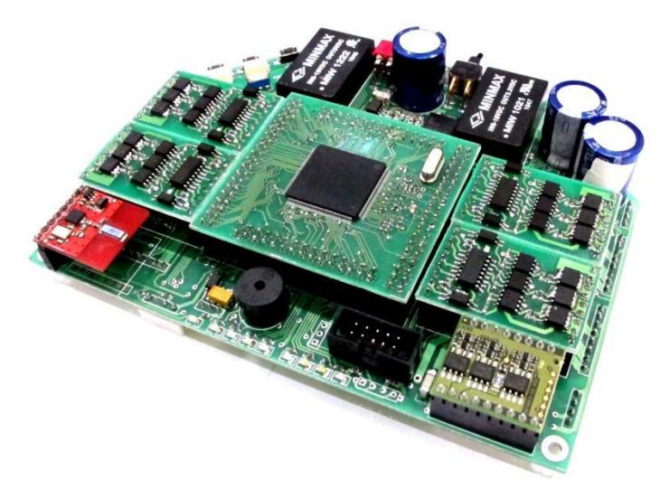
Current main board is the product of 4 years designing and evaluating. Last years, we've got problems mainly with connectors and isolation. Fig. 11 shows the main board of the old robot that is going to change to unified board this year. We have tried to make as less as possible changes to the old board. Main changes are stated bellow in different subsections.
3.1.1 Processor
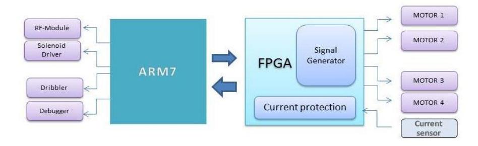
Because FPGA has real time qualities, in the past years we have implemented our electronic aims on FPGA. There were some difficulties and limitations. For example we couldn't debug it. So we decided to use FPGA only as motors controller and all the remaining tasks are done by an ARM7- Microcontroller those are connected to each other by an interface. Although some of our projects in ARM7-microcontroller are still under development.
3.1.2 Optoelectronics
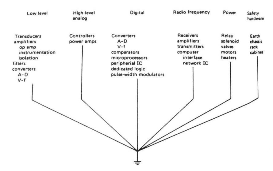
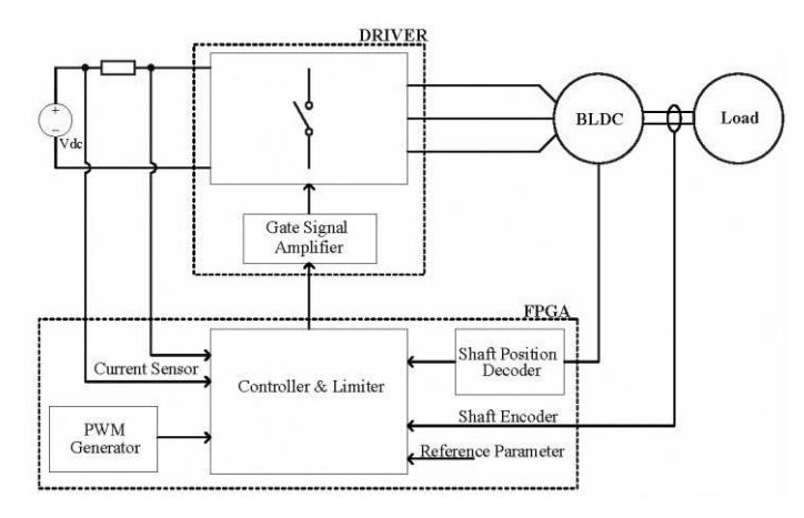
In the past year we isolated all the signals in the Power and Logic sections. That was not necessary, but it solved our high voltage and motor drivers' problems. But designing circuits using optocoupler can cause problems like a 10 KHz maximum working frequency, high power dissipation due switching and occupying a large space. But it prevents system failures. In direct-coupled method working frequency can be up to 1 MHz and Power dissipation due switching is low, but designing circuits needs a lot of experience to reduce noise and interference. Therefor direct method's advantages made us reconsider our previous decision to use optocouplers. In the figure 12 below the correct procedure of connecting different parts of circuits' Ground can be seen.
3.1.3 Motor Drivers
Integrating the circuit's board and removing the motor driver modules and also Utilization of maximum velocity and Power are from this year's goals. Right now we are using 4 cell batteries that produce 16.8 volts in the maximum charge mode. That is less than motors' nominal voltage. Therefore motors driver circuit is being redesigned. One other thing we want to do is to use two N-Channel transistors in high side and low side for switching the motor windings. P-Channel MOSFETs have lower switching current density. Therefore Using dual N-Channel MOSFETs provide higher current conduction of outputs, but it needs more components. On the other hand MOSFET drivers are available in Integrated Circuits and there is no need for designing expanded circuits [6].
In addition to advantages that Bootstrap Gate Drivers have, they have some limitations, on time of duty cycle is limited by the requirement to refresh the charge in the bootstrap capacitor and serious problems occur when the negative voltage is presented at the source of the switching device. Design procedure of bootstrap components is very important. And if we don't consider vital parameters it leads to Latch-Up problems and missing pulse in the high side switches.
3.1.4 Motor Current Protection
To protect the Brush Less DC motor and power switches, we should control the current not to rise above the limits. On way to achieve that is to reduce PWM temporary to zero at once. And the other is to measure the current in ADC constantly and reduce the PWM by a controller. In the first method because of multiple switches it's likely for the Motor Driver Circuits to face problems. Therefore the second method was considered. This method is hard to implement but it makes the motors' movements smooth [7].
3.2 Batteries and protection
Each robot is running on two pack of Li-Polymer (Dualsky™ – xp17002ex) batteries with total voltages of 16.8 volts and capacity of 1700 mAh. These kinds of batteries are very sensitive to overuse. If the voltage of each cell is dropped below 3 volts, the cell would be damaged permanently. Hence, a battery protection circuit and a low voltage alarm (buzzer) are used. This circuit turns the system off when voltage of each pack is dropped below 6.8 volts and the alarm goes on when the voltages dropped below 7 volts. It also sends the voltage value back to the AI system to be monitored.
3.3 Wireless communication
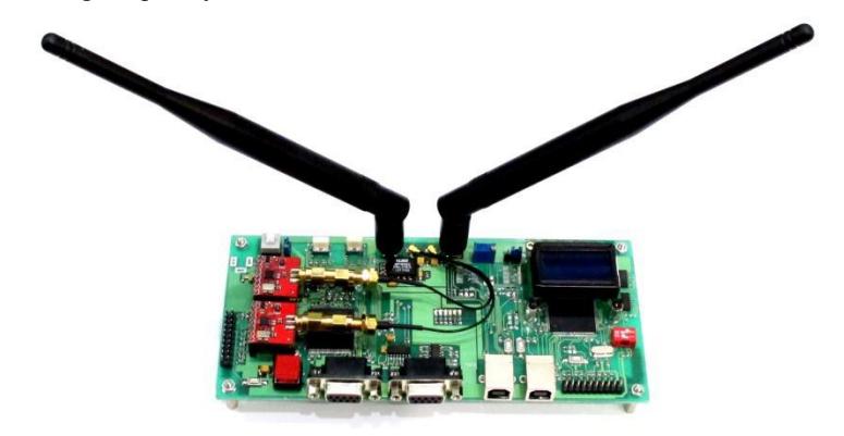
The communication between robots and AI system is done by using two nRF2401 transceivers. These modules work in frequency between 2.4 to 2.525 GHz. Designing printed circuit board (PCB) of RF circuits needs special skills and facilities, so the ready to use module (sparkfun™ – WRL00691) was used.
A wireless board (Figure 13) was also designed to ease the process of sending and receiving packets from modules to AI system. Since changing each module from the receive mode to the send mode consume some time, two separate modules are employed to decrease this delay. The output power of nRF2401 chip is limited to 0 dbm, so a radio amplifier (BBA-519-A) is used to increase the output power up to 18 dbm (50 mW).
The environment of Robocup competition has lots of interferences caused by different teams. An intelligent algorithm was used to scan different frequency channels and calculate data loss in each one. After that, the best frequency will be used as working frequency.
3.4 Kicking system
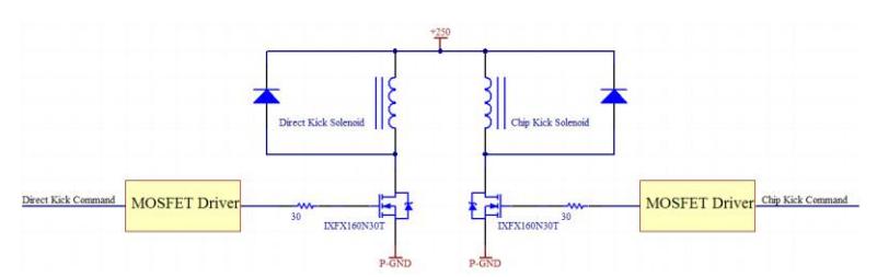
The kicker system in robot is working based on the force created by a ferromagnetic plunger in the coil of the solenoid. Force created in the solenoid is depended on several factors, including number of turns in the coil, material of the plunger, its weight, the value of the current in the coil, duration of switching of power MOSFET and extra mechanical factors.
There are two separate kicker systems in the robot. One cylindrical type is used for direct kicks and another flat type is used for chip kicks. Therefore, two separate MOSFETs were used to flow current in solenoids when it is needed. The circuit for driving solenoids is presented in Fig 22.
3.4.1 Solenoid Optimization
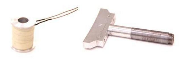
Based on the Newton's second law, to achieve a higher acceleration in movements, reducing the weight of the robots is very important. The solenoid has a high potential for losing weight. All the mechanical limitations of this structure and Plunger have been considered. Designing an optimized solenoid needs a great amount of knowledge and experience in electromagnetic. Thus to make calculations easier we used FEMM software. After prototype of the cylindrical solenoid and all the components are drawn, we attach the material properties to the components. FEMM calculates the force that acts along the direction of the perturbation. During that procedure we found out that there are some limitations because we don't analyze our flat solenoid. For example the capacity and voltage of the capacitor cannot be changed because we want to keep our last year's chip kick ability. After a lot of experiments the result of this analysis was approved. Among 4700 simulated cylindrical solenoids the one with the most suitable weight and other parameter was chosen. This resulted to a 90 grams reduction from plunger and structure of cylindrical solenoid's weight with the same kick speed.
3.5 Motor
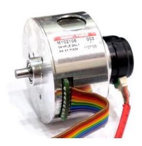
The robot has 4 Brushless DC Motors (BLDC) to perform precise motions. BLDC motors are MAXON™ flat motor (EC45 - 50 watts) with custom back extended shaft combined by US Digital™ E4P encoder with 360 counts per revolution which is 1440 pulse per revolution (Figure 15). In dribbler module, a MAXON™ EC16 - 50 watts motor is used as an actuator. To drive this motor, ready to use module (DEC module 24/2) is used.
4 Mechanical Design and construction
The mechanical system of small size robot consists of the wheels, stands, chassis, kickers, the dribbler and the robot cover. Some problems in the last version of MRL small size robots encouraged us to change the materials and mechanical design. At the beginning of this year research, we have done many analyses to reach the most suitable design for each part of the robot. The diameter of the new robot is 179mm and the height is reduced to 140mm. The spin back system conceals 20% of the ball diameter in maximum situation. Different parts of our new mechanical design are described in the following. Figure 17 shows our newly designed robots that are attended in Iran Open 2012 competitions. The motion of the new robot was acceptable, while there is some problems in the dribbling systems. We hope to resolve the remained problems till RoboCup 2012 competitions.

4.1 Wheels
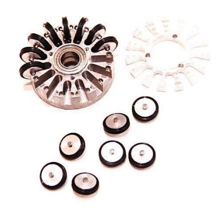
We tried not to have any specific change in the robots but to improve the Omni-Directional wheels for a smoother movement in the field. In order to provide a better system we found out that it's better to use pins instead of steel rings and this has the following listed merits:
- Decrease of friction between O-rings and the wheels which causes a higher speed in robot system.
- Less involvement of O-rings with the field's surface which would help and ease the cleaning procedure in the O-rings.
In the replacement procedure (replacing the steel rings with the pins) we had to construct the wheels from the base. Consequently it led to an improvement in the wheels system. Therefore we decided to change the ratio of gears and the diameter of wheels by applying the same ratio which has been used by Skuba team:1:3.60. This made us to decrease the diameter of wheels to 52mm with respect to the use of EC45 50watt motors which had a gradual result in total speed 5 m/s and an acceleration of 4 .
4.2 Motor's Stands
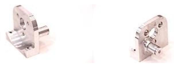
Due to sudden collisions of robots we decided to change the stand's shafts and strengthening them. This was made by using a fillet in stand's design as illustrated in the figure. This amplifies the strength.
4.3 Chassis
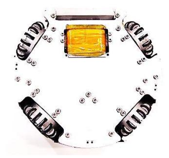
In the chassis section there was no specific change. In order to avoid any warp due to lathing in the system, we decreased the time of lathing on the chassis. The application of multiple screw types in the previous version of the robot was decreased to only one type which created an ease in dealing with the robot.
4.4 Kickers
The robot uses two kinds of kicking system, direct kick and chip kick. Each of them is divided in two part, solenoid and plunger. The magnetic plunger material is pure iron ST37. Because of the electromagnetic effect two separate parts are used in the cylindrical plunger. The custom-made cylindrical solenoid is used for direct kick which has ability to kick the ball up to 12 m/s. Last year our direct kicker was made from Aluminum alloy but the kickers were broken frequently during the matches. To solve this problem, we replaced it by Titanium Alloy for the new robot. Direct kick solenoid is located between kicking plates which are made from polyamide and aluminum.
As a second kicking system, MRL2012 has a custom-made flat solenoid. Because of space limitation with high performance chip kick we decided to reshape the solenoid from cylindrical to flat rectangular and placed in the front part of the robot. The chip kick has a 45 degree hinged wedge front of the robot which is capable of kicking the ball up to 6m before it hits the ground. The chip kicker is made from Aluminum Alloy 7075 which is enough strong to kick the ball. Chip kick system has a different plunger from direct kick; chip kick plunger is made from Steel with the thickness of 3.70mm.
4.5 Dribbling System
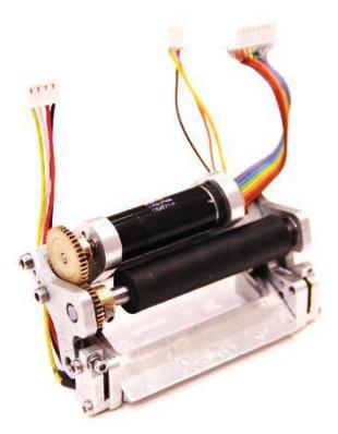
Dribbling system is a mechanism to improve the capability of ball handling. Dribbler is a steel shaft covered with a rubber and connected to high speed brushless motor shaft, Maxon EC16 Brushless. We examined several materials for dribbler bar, like Polyurethane, Silicon and carbon silicon tube. Carbon Silicon is selected for its higher capability in ball handling.
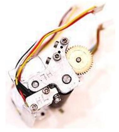
The spin-back motor was in the front of the robot and it was exposed to any strike whether due to ball hit or robot's collisions. To solve this problem, we have taken the spin back motor's position a little back. Additionally, by attaching the ending point of the spin-back motor with a fastener to spin-back system we fixed the structure. This led to a higher resistance in front of any hit and it also helped the opening and fastening of the dribbling system.
4.6 Protection Cover
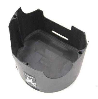
Because of heavy collision with other robots or being hit by the ball we decided to use a more resistant cover made of carbon and glass made by a composite procedure. We found out glass and carbon fiber in ingredients of cover had an unwanted impact on wireless receiving system. By changing its material to polyethylene the problem is solved. The new cover is about 50-60 grams lighter and it is fixed without any screw on the robot.
References
- Bakhshandeh, O., M., Sharbafi, "Modeling and Simulating of Omni Directional Soccer Robots" 2011 IEEE 3rd International Conference on Computer Modeling and Simulation (ICCMS 2011), Mumbai, India, (2011).
- Browning, Brett; Bruce, James; Bowling, Michael; and Veloso, Manuela M., "STP: Skills, Tactics and Plays for Multi-Robot Control in Adversarial Environments" (2004). Robotics Institute.
- Samuel, A. L., "Some Studies in Machine Learning Using the Game of Checkers". IBM Journal of Research and Development, no. 3, pp. 210–229, (1959).
- Sutton, R. Learning to Predict by the Method of Temporal Differences. Machine Learning, no. 3, pp. 9–44, (1988).
- Sharbafi, M.A. Lucas, C. Daneshvar, R., "Motion Control of Omni-Directional Three-Wheel Robots by Brain-Emotional-Learning-Based Intelligent Controller", Systems, Man, and Cybernetics, Part C: Applications and Reviews, IEEE Transactions on , vol. 40, no. 6, pp. 630-638, (2010).
- Maxon motor, Key information on maxon DC motor and maxon EC, Maxon Motor Catalogue, 2010.
- A. Azidehak, M. Hoshyari, M. A. Sharbafi "Design and Implementation of Minimal Components Brushless DC Motor Driver for Mobile Robots" 2011 IEEE International Conference on Mechatronics, Istanbul, Turkey, (2011).
- Sharbafi M.A., Azidehak A., Hoshyari M., Bakhshande Babersad O., Adhami-Mirhosseini A., Zareian A., Esmaeely D., Ganjali A., Esmaeelpourfard S., Jamaati H., MRL 2011 Extended Team Description, In Proceedings of the 15th International RoboCup Symposium, Istanbul, Turkey, (2011).