OMID 2012 Team Description Paper
Seyed Arman Alaie, Masoud Abdi, Davoud Abbasi, Mohammadreza Sarbandi, Siyavash Asadi, Mojtaba Najafi, Mehdi Hosseinzadeh, Mohammad Sajad Manuchehri, Asadollah Kiaei, Mostafa Abdolghafar, Abbasali Forouzideh, Saeed Alikhani, Ehsan Darestani, Saeed Keshavarzi, Seyed Mahdi Nasiri
Electrical Engineering Department; Computer Engineering Department; Bioelectrical Engineering Department; Mechanical Engineering Department; ECE Department, Shahed University of Tehran, Iran
Abstract This Paper is a general description of OMID 2012, one of the Robocop Small Size League teams. The description includes hardware of robots and a general overview of software architecture. This time we have some improvement that include a complete new software design, noise avoiding ball detection, new design of robots main board.
1 Introduction
The Omid robotics team is a branch of robotic society of ECE department of Shahed University. Our team started the Small-Size League in summer 2007 with the effort of former member. Now OMID is working with new members and formers are as guiders. Here is an overview on the robots preparation and performances of each part respectively and all together.
2.1 Driving System
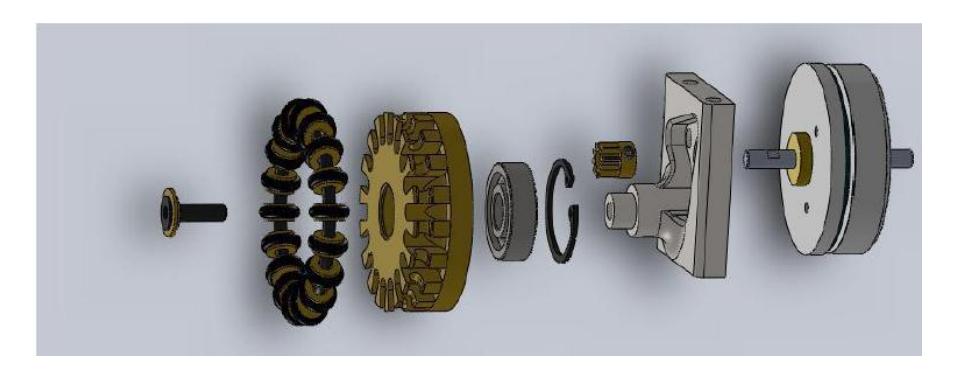
The main plan of robot is made of Aluminum. 4 Omni-directional carry the main body, each wheel is coupled to an EC-45-Flat brushless 30 watt motor via a 1inverse gear with a transmission ratio of 1:5. These Wheels are fully designed in one piece and no screw has been used in the structure of wheels. This feature causes more efficiency, more wheel life time and simplicity in design.
2.2 Kicking System
There are two solenoids that help to kick the ball, both for direct and chip kick. A flat plunger is made of steel, 4mm thickness. Direct kick plunger is made of two materials. The first part material is magnet which is steel, and the second part is made of a material with no magnetic property such as Aluminum. This feature causes a powerful kicking system.
2.3 Spin-Back System
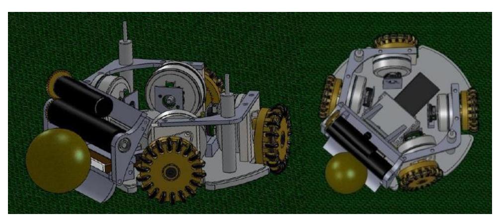
The Spin-Back module is driven by 15 watt Maxon EC16 with a transmission ratio of 2:1. As we have in Small-Size League rolls the robots must have specific dimension, our robots have 178mm of diameter and 148mm of height and also each robot covers less than 20% of ball. The whole robot is about 2.5 kilograms weight. 3D simulation models shown in Fig.2 are created with SolidWorks.
3 Electrical Systems
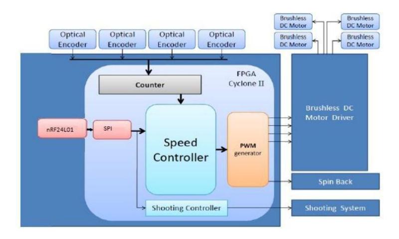
The main board consists of Altera FPGA as main controller. We are using PI controller in order to drive all motors. Each wheel's motor is equipped with an encoder to generate the feedback signal for PI controller. Communication between robots and computer performed with nRF24L01+ module from Nordic Semiconductor. It occurs in 2.4GHz to 2.525GHz band with 1Mbps rate.
The motor drive circuit, wireless communication part, and main control circuit are designed in a single board rather than the shooting circuit, which connect to the main board by small cables.
3.1 Central Control
We use a Cyclone III FPGA as the main controller to generate all control signals for motors [2]. The full duplex wireless communication system receives the command packet from the AI and sends the robot status to AI. Once a packet arrives, it has to be decoded and processed with the data of hall sensors and encoders to generate signals to handle motor drivers and shooting system.
3.2 Motor Driver
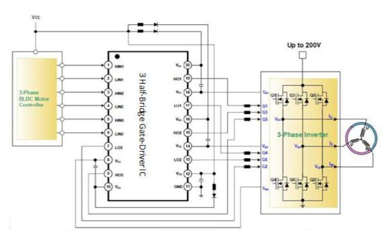
This part drives 4 brushless DC motors and 1 brushless DC motor for Spin-Back. Motors are driven by 3 Half-Bridge Gate-Driver IC. This chip is a monolithic three half-bridge gate-drive IC designed for high-voltage, high-speed driving MOSFETs and IGBTs operating up to +200V. It's shown in figure.3. And The spin back motor are driven using L6235 chip.[1]
3.3 Shooting System
There are two kickers, a direct kicker and a chip kicker. We developed the flat kick system to kick in maximum velocity, approximately 8 m/s. The kicker board can charge two 2200μF capacitors from 0V to 250V in about 5 seconds with 2A average current.
3.4 Communication
The communication between robots and computer performed with nRF24L01+ module. The nRF24L01+ is a single chip 2.4GHz transceiver with an embedded baseband protocol engine (Enhanced ShockBurst™), suitable for ultra low power wireless applications. The nRF24L01+ is designed for operation in the world wide ISM frequency band at 2.400 - 2.4835GHz. Enhanced ShockBurst™ is a packet based data link layer that features automatic packet assembly and timing, automatic acknowledgement and retransmissions of packets. Enhanced ShockBurst™ enables the implementation of ultra low power and high performance communication with low cost host microcontrollers. The Enhanced ShockBurst™ features enable significant improvements of power efficiency for bidirectional and unidirectional systems, without adding complexity on the host controller side.
4 Software
The robots software is separated to two main sections. Visioning software and Game play algorithms.
4.1 Vision
For purpose of real time image processing and object recognition, we use two cameras (The Stingray F-046B/C's high resolution) and SSLvision software. The whole artificial intelligence is on one computer receiving the data of SSLVision and Referee in each frame and uses them to make decision.
4.2.1 Operational Functions
Functions of this section are categorized in three levels. Low, Medium and High Level Functions.
High Level Functions
These functions specify the current skill of the robot such as taking a defensive position, Goal kick, corner kick, passing the ball and so on. To do a high level function we need to make it closer to machine language, so we use medium level functions to do this task.
Medium Level Functions
Functions in this level are mostly common robot actions. For example one of these functions is "Moving In Field" so we can move and turn in field with this function. As you can see again we need to get closer to machine languages so we use low level functions.
Low Level Functions
Low Level Functions are the robot basic behaviors including: exactly addressed movements, stop, spin back On/Off, direct kick and chip kick. Functions in higher levels are interpreted to the low levels in order to execute the result of an appropriate command and send to the robot circuit via our communication device.
As an example when the Decision Section (4.2.2) chooses the defensive state for a robot, the high level function will be set to "defense", consequently the medium level function will be set to "move in field" and then related low level functions such as gotoXY, stop, spin back,… will be executed so the command packet is ready to be sent to specific robot.
4.2.2 Decision making Section
The most important intellectual section is decision making section. In this section functions use data of SSL-Vision, SSL-Referee-Box and Robot Agents for current status of play and predictions of the next status in order to chose and decide a proper high level function.
4.3.1 Game Simulator
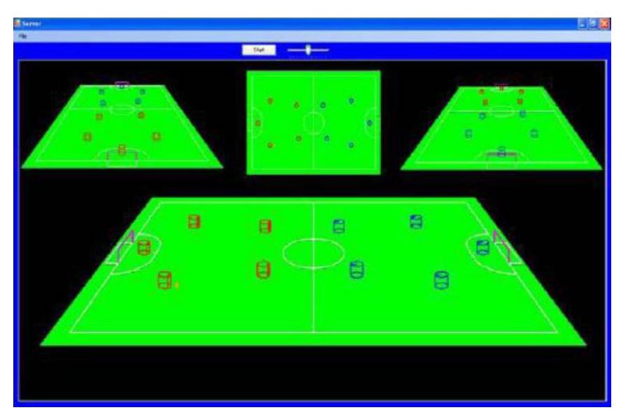
To test the Game Play Strategy Algorithms (4.2) without having two full robot teams and a play field, a Game Simulator GUI is prepared. In this way the Algorithm testing and error correction is done much easier regardless any physical and hardware problems and needs.
4.3.2 Game Manager
To monitor and control all robots in the game field, Monitoring Software is programmed that will be installed on the off board controlling system. The robots location and ID on the play field is received from the visioning software and simulated. In other word this software manages the game play.
References
- Vincenzo Marano, "L6235 THREE PHASE BRUSHLESS DC MOTOR DRIVER" Application Note,ST,2003.
- Altera, "Cyclone III Device Handbook"