Parsian (Amirkabir Univ. Of Technology Robocup Small Size Team) Extended Team Description for Robocup 2012
Vahid Mehrabi, Ali Koochakzadeh, Seyed Saeed Poorjandaghi, S.Mehdi Mohaimanian Pour, Erfan Sheikhi, Alireza Saeidi, Pourya Kaviani, Sina Saharkhiz, Ali Pahlavani
Mechanical Engineering Department, Sharif University of Technology; Electrical Engineering Department, Sharif University of Technology; Electrical Engineering Department, Amirkabir Univeristy of Technology; Mathematics and Computer Science Department, Amirkabir Univ. of Technology; Mechanical Engineering Department, Amirkabir Univeristy of Technology; Mathematics and Computer Science Department, Sharif University of Technology; Electrical and Computer Engineering Department, University of Tehran
Abstract This is the extended team description paper of the Robocup Small Size Soccer Robot team "Parsian" for entering the Robocup 2012 competitions in Mexico. In this paper we will represent detailed description of our robots' hardware design, as well as the software architecture in detail with focus on new improvements that have been made since last year. Improvements and developments that seemed innovative and useful like our approach in new mechanical design, important parameters that should be considered during design, improvements on planinng structure and enhancements in predefined plays, a high speed positioning evaluator will be discussed in detail.
1 Introduction
''Parsian" small size soccer robots team, founded in 2005, is organized by electrical engineering department of Amirkabir University of Technology. The purpose of this team is to design, build and program a small-size soccer robots team compatible with International Robocup competition rules as a student based project. "Parsian" team is a group of ten active members with electrical, mechanical and computer science/engineering backgrounds. We have been qualifed for six consequent years for the international RoboCup SSL. We participated in 2008, 2009, 2010 and 2011 RoboCup competitions. Our most notable achievements are being awarded second place in RoboCup Iranopen 2012 competitions and second place in Robocup 2010 SSL's technical challenges.
In this paper we first introduce our robots' hardware (section 2). Our new mechanical design will be discussed In section 2.1 and our electrical design will be covered in section 2.2. Section 3 explains our software framework including high level planning algorithm and low level control algorithms.
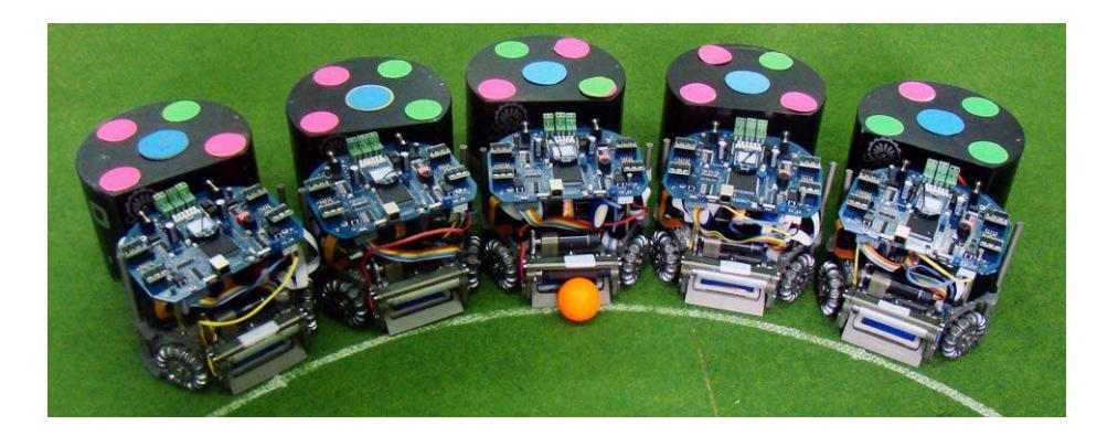
2 The Robot's Hardware
2.1 Mechanical Design
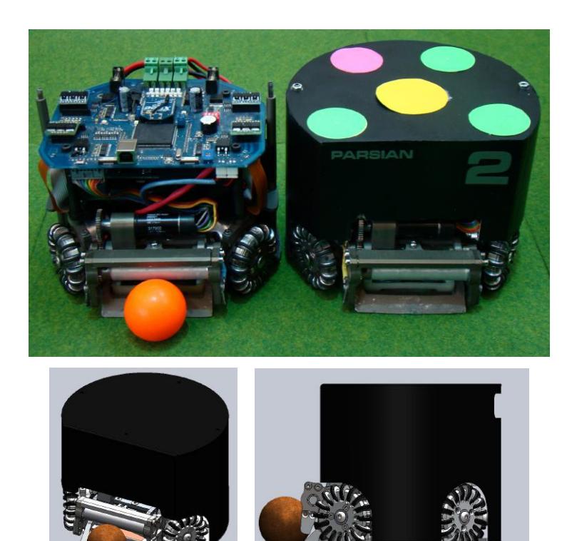
In this section we are going to describe the mechanical system and design procedure of our robots which consists of drive system, dribbler, kickers and so on. The dimension and other major parameters of our robots are described below. Figure 2 shows our 3D CAD model with our real robots with and without cover.
Robot Specifications
| Parameter | Value |
|---|---|
| Robot Diameter | 178 mm |
| Robot Height | 138 mm |
| Ball Coverage | 19 % |
| Max Linear Velocity | 3.5 m/s |
| Weight | 2.0 kg |
| Maximum kick speed | 15m/s |
| Maximum chip kick distance | 7.0 m |
| Maximum passing ball speed catching | 5m/s |
After Robocup 2010 we decided to design a new type of robots that are more accurate, agile and reliable. So in order to specify the design process we introduce some major goals for our robots that must be in mind during design, and those are:
- Minimum possible size for all of the parts (until you were bounded by other constraints such as strength criterion) in order to reach lighter parts, more agile robots and also less damage to motors.
- A little more complex part is better than two simple parts. Due to possible damage of robots and necessity for replacement, less part is a criterion in design.
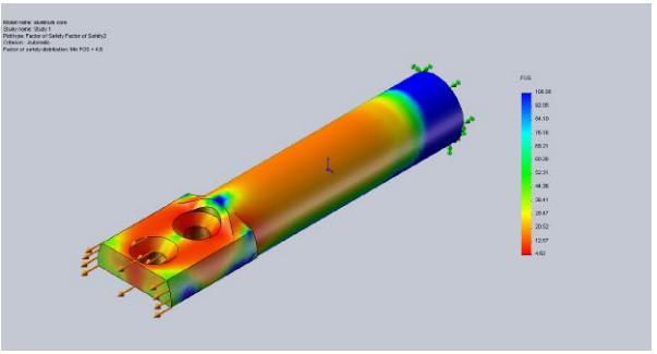
- Strain and displacement criterion is more important that stress criterion. In some components failure will cause due to relative displacement of parts and not fracture of them. For example chipper head may be deformed (not broken) due to high impact of solenoid bar that causes failure.
- Every heavy component must be as low as and also as behind as possible. Because high amplitude of acceleration and deceleration in motion of robots, center of gravity plays a major role in maximum possible amplitude of agility.
- Reliability is one of the most important points in design. Tolerances in parts and between moving object must be in an acceptable range in all of the robots in order to have homogenous robots.
These are the facts that we considered during the design of our 2011 version robots. However after Robocup 2011 we realized some minor fault in wheels, dribbler and base plate that was fixed after. These changes lead us to another criterion in design:
- All of touching parts with ground (except friction make parts) must be as smooth as possible in order to have smooth motion.
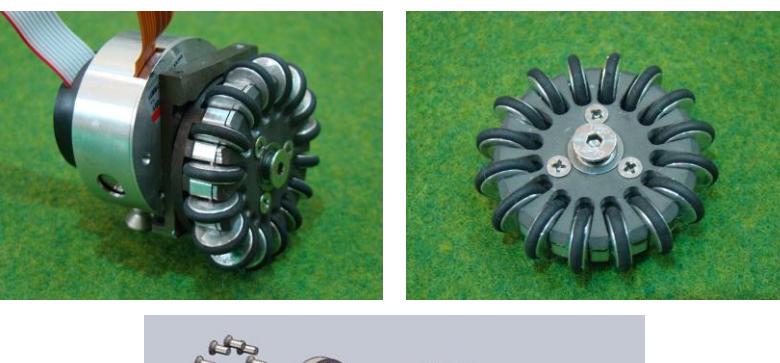
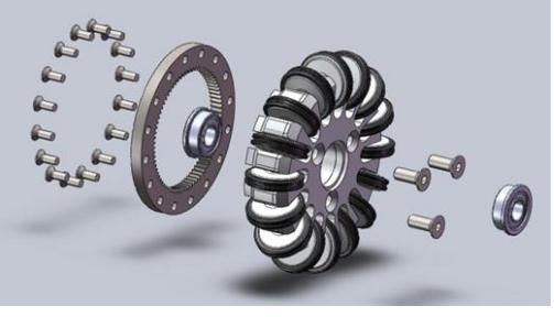
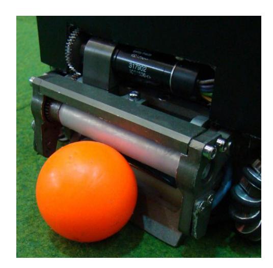
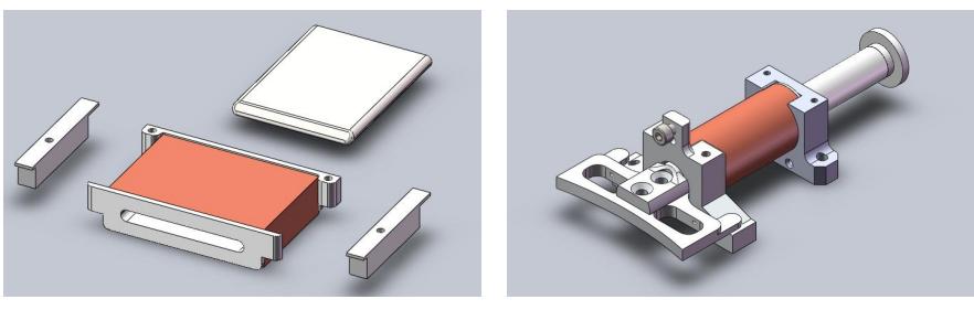
In later section we will introduce more details of our robot components.
2.2 Electrical Design
Our electronic system consists of two electronic boards, the main board and the kicker board. The main boards platform is based on a single chip Xilinx Spartan XC3S400 FPGA which in charges for wireless communication, BLDC motor driving, Executing the low-level control loop and sending control signals to the kicker board. On the other hand an ATMEGA8 microcontroller is used to perform charging/discharging tasks in a controlled manner on the kicker board.
Main Processor FPGA devices are mainly appropriate for parallel algorithms implementation. Nevertheless sequential algorithms, particularly those that dont need vast processing power, are easier to implement as a program for a microcontroller. Due to less power consumption, simpler board layout and fewer problems with signal integrity and electromagnetic interface, we preferred to have both microcontroller and FPGA array based features combined in one chip. Consequently quadrature decoder, PWM generation, BLDC sequence generator modules and serial communication are implemented in a hard CPU core which is dedicated part of the integrated circuits, whereas sensors data decoder, controller loop handler and other modules are implemented in a soft CPU core which utilizes general purpose FPGA logic cells. We implemented a TSK3000 based soft processor on the FPGA. We use Altium Designer software to change processor or modify the code running on it. To debug a phase of a design we utilize a standardized debug interface via JTAG bus.
Motor Overcurrent Protection We use two overcurrent protection manner to protect a BLDC from a receiving more than an exact Ampere of current. In the first method if an overcurrent state is noticed by the software through the real-time reading of current sensors data, the PWM duty cycle will be narrowed up to the normal situation. In the second method a simple motor overcurrent circuit is employed to cut the motor from its power supply when the overcurrent situation is occurred. A current sensor measures the input current and yields a corresponding voltage signal at its output. This output is connected to the input of an analog comparator, with the other input coming from a reference voltage source of specified ampere of current to be created. If the output of the current sensor is greater than the specified value, the comparator will output the signal. This signal is then hooked into a MOSFET switch. In an overcurrent situation the switch will cut off the power to the motor and protect it from too much current.
Low Level Control Two types of control commands are sent to the robots from the remote Host PC, the motor rotational speed type and the robot velocity type command. The former contains velocities for each motor and the latter contains velocities of robot along x and y axis and angular velocity of the robot. The quadrature decoder units implemented on FPGA decode each motors attached encoders signals. These decoders count digital pulses and calculate the speed of each motor. If the robot receives the velocity type command, the robot velocities are calculated by means of the transformation of four motors rotational speed. The desired velocity commands and the current calculated velocities are then fed into a cascade control system. Robot velocities as primer variables are controlled by adjusting the set point of each motors rotational speed as related secondary variables controller. A discrete PID controller acts as primary loop controller, which controls the robot velocities.
A discrete PI controller acts as secondary loop controller, which reads the output of primary loop controller as set point, then the reference rotational speed of each motor is calculated using the transformation matrix. When the reference rotational speed is given to each motor, the PI controller generates the PWM control signal. Then the robot can reach its desired motion. Obviously if the robot receives the motor rotational speed type command, just the secondary loop controller performs the control action. Reasonably the robot has slip between the wheels and the ground in some amount. In absence of a sensor that measures the robot velocity, this slip cause an error between actual motion and the desired one. By means of an extended Kalman observer for state estimation which is implemented at the high level control loop, this error will be compensated. The performance of the compensation depends on how well the robots velocity is estimated by the extended Kalman.
3 Planner
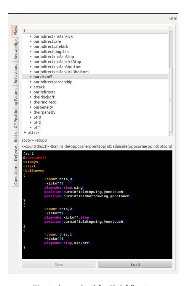
In this section we skip many part of our planner and just describe our high level planner with focus of our Script language and behaviors of any role.
3.1 High Level Planner
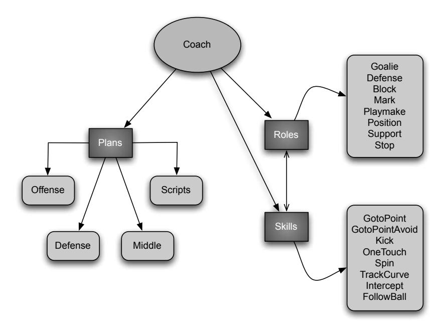
The Coach layer is the first step in the high level planning (decision making) loop. Choosing a formation for the team is done prior to any other decisions. According to policies, that are a mixture of manual configurations and gamestate dependent updated values, each cycle the coach layer decides the team's formation. Therefore, each agent takes part in one of the main plans: defense, midfield and offense.
In This year we have changed our high level planner a bit and added a layer called Plans , in our game-On play we use this method which contains 3 main plans as mentioned , the defense plan works individually that contains our Goalie and defenders but middle and offense plans are cooperating together and the number of agents these plans should have is based on the manner of opponents , if the opponent team is ball owner and attacking us the middle plan will have more agents than offense and vice versa . Middle plan agents intend to possess the ball owned by opponent and diminish their attacking opportunities with marking, blocking, ball interception and etc. Offense plan includes agents that are going to create attacking chances to score. One agent always takes the role of the "playmaker" (the agent that possesses the ball), other offense agents should take suitable positions or support the playmaker during contention of our playmaker and an opponent robot. But in our non-Play-on ,when the game stops by referee and starts with a direct or indirect kick for any team, we use old method and give any agent a role to execute. After running the plans, a set of roles are assigned to some of agents that arent controled directly with plan and can have an individual role , this role assigning occur in an optimized way, so that minimum movement is needed for agents to execute their roles.
To perform a role, each agent may use a different set of basic skills. For example "marker" itself is a role but it uses the "gotopoint" skill to reach its target. The hierarchy of the coach structure is shown in figure 6.
Offense Plan
1. Playmaker
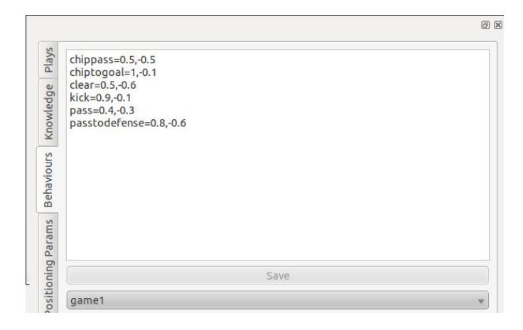
Playmaker is the agent that owns the ball and plans to make appropriate pass/shoot commands to create scoring opportunities. Playmaker can choose an action between passing, shooting, one touch kicking and spinning the ball. There are some evaluation functions that predict success rate of each one of the above-mentioned actions. Then playmaker chooses the best action using these probabilities and some pre-defined constants that predict priority of each one of the actions. For example most of the times playmaker should find a way to kick the ball, so kicking has the highest priority, thus has the highest constant. The set of all constants creates the attacking behavior of the team.
2. Positioning
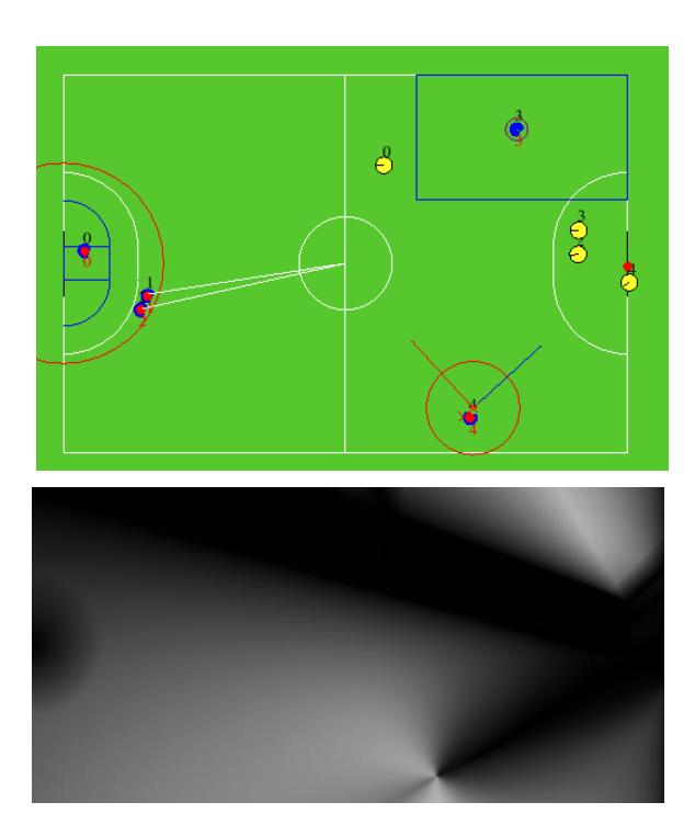
The other agents in the attack plan are only searching for suitable positions for catching probable passes or blocking opponent agents. For each point of the field some features like goal-visibilty, angle to shoot, openness, distance to goal, cornerness and distance from opponents are evaluated and mixed using a power weighted multipication. Because the process is done for each point of the field, it is necessary to find a way to accelarate this compution. We used CUDA and OpenCL for this purpose to benefit from the parallel processing power of the modern GPUs. A sample of our positioning output is depicted in figure 9(b). The process could be done with a rate of 10 times per second.
References
- OpenGL the industry standard for high performance graphics (2011), http://www.opengl.org/, [accessed February, 2011]
- Browning, B., Bruce, J., Bowling, M., Veloso, M.: STP: Skills, tactics, and plays for multi-robot control in adversarial environments. Proceedings of the Institution of Mechanical Engineers, Part I: Journal of Systems and Control Engineering 219(1), 33–52 (2005)
- Bruce, J., Veloso, M.: Real-time randomized path planning for robot navigation. Lecture Notes in Computer Science pp. 288–295 (2003)
- Bruce, J., Veloso, M.: Safe multirobot navigation within dynamics constraints. Proceedings-IEEE 94(7), 1398 (2006)
- Monajjemi, V., Atashzar, S.F., Mehrabi, V., Nabi, M.M., Omidi, E., Pahlavani, A., Poorjandaghi, S.S., Sheikhi, E., Koochakzadeh, A., Ghaednia, H., Pour, S.M.M., Behmand, A., Rastgar, H., Arabi, M., Nouredanesh, M.: Parsian - team description for robocup 2010 ssl. RoboCup 2010
- Nokia Inc.: Qt A cross-platform application and UI framework (2011), http://qt.nokia.com/, [accessed February, 2011]
- Poorjandaghi, S.S., Monajjemi, V., Mehrabi, V., Nabi, M.M., Koochakzadeh, A., Atashzar, S.F., Omidi, E., Pahlavani, A., Sheikhi, E., Behmand, A., Pour, S.M.M., Saeidi, A., Shamipour, S., Karkon, R.: Parsian - team description for robocup 2011 ssl. RoboCup 2011
- Smith, R.: ODE Open Dynamics Engine (2011), http://www.ode.org/, [accessed February, 2011]
- Zickler, S., Laue, T., Birbach, O., Wongphati, M., Veloso, M.: SSL-vision: The shared vision system for the RoboCup Small Size League. RoboCup 2009: Robot Soccer World Cup XIII pp. 425–436 (2010)