RFC Cambridge
Rui Jin, Aaron Rameriz, Svilen Kanev, Lisa Liu, Baker Logan, Marcel Thomas, Benjamin Johnson, Arshia Surti, Elizabeth Schanne, David Wu, Siddarth Chandrasekaran
Massachusetts Institute of Technology, Cambridge, MA 02139, USA; Harvard University, Cambridge, MA 02138, USA
Abstract Past problems such as kicking failure and inconsistent behavior have been addressed by redesigning and brushless boards and break beam sensors, upgrading components, and designing a new way of mounting the encoders. Accessibility to internal components was improved by redesigning the sheilds. Lastly, new strategies were implemented and a monitoring system was put in place to gather statistics.
1. Team Description
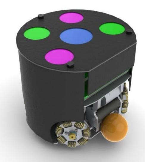
RFC Cambridge is a joint MIT-Harvard team in its sixth year of competition in Robocup. We participated in the international Robocup competition in 2006, 2007, and 2009, as well as the US Open in 2008, 2009, and 2010. The team consists of approximately fifteen members split working in four integrated subteams: mechanical, electrical, computer science, and controls. We are the only Harvard-MIT organization, one of few engineering clubs at Harvard, and one of the few completely undergraduate-led RoboCup teams. Our robot team consists of 5 robots with omni-directional wheels powered by a brushless motor system. Each robot has a rubber-coated dribbler and an electro-magnetic solenoid for planar kicking. The current height of the robot is 15cm; the maximum diameter of the Robots projection to the ground is 18cm; and the maximum percentage of ball coverage is approximately 19.
2. Hardware
2.1 Solutions to Known Problems
Last year's focus was on the kicker module and a prototype wheel design. In the fall of 2011, we focused on redesigning the shields and our method of mounting the motor encoders; in the spring of 2012 we plan to implement and field an improved dribbler design.
2.2 Shield redesign
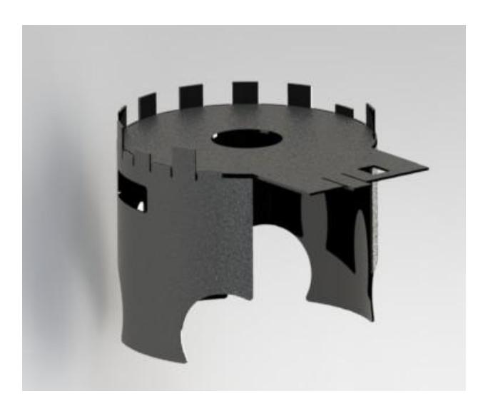
The new shield design was designed with the idea of increasing its robustness; the previous shield iteration was a two-piece design made of 1/16" ABS sheet consisting of a cylindrical "side" attached to a flat circular "top" plate. The two plates were bonded using epoxy; however, it was found that this was a very fragile solution, as the epoxy would frequently come undone. As more and more layers of epoxy were applied to the shield, it was clear that a new design was needed.
The new design is still a two-part concept; however, in this concept, the side now has tabs folded at right angles. The top plate is attached by bonding these tabs and the top plate together using a cyanoacrylate adhesive. While no formal impact testing was done, it was found that the shields could survive being thrown across a room; thus it was judged that its strength was satisfactory.
2.3 Encoder mounting redesign
One module that has been a consistent problem is the motor velocity feedback; our current method of mounting these is susceptible to failure and fixing these modules in the field is time consuming and often means a robot must be taken out of the game.
The motors that we currently use do not have a shaft protruding from the back; therefore we cannot mount an encoder in our current drivetrain design unless we machine an additional shaft and bond it to the motor. Currently, we turn down an aluminum rod and epoxy it to the back of the motor; however, with fatigue this bond eventually fails and the encoder shaft detaches from the motor. This leaves us with a motor that does not have feedback and cannot be effectively used to control the robot.
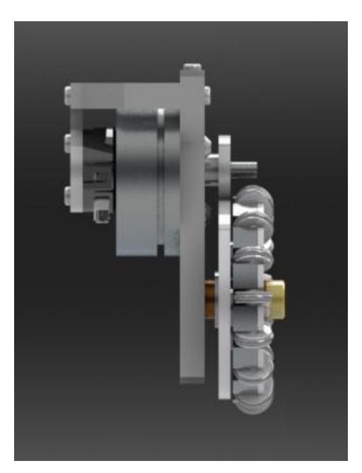
The idea we are pursuing this year is to push some of the excess shaft through the motor such that it pokes out of the other end of the motor; we can then utilize this secondary shaft to attach the encoder discs without having to worry about the encoder shafts breaking off. We have tried this idea before, but previous efforts ended in irreversible damage to the motors. Our current approach has us using custom designed jigs to hold the motors while other features on the jig allow us to carefully apply a load to the motor shaft, the idea being that a pure compressive load will not damage the motor and will allow the shaft to slide through, whereas previous attempts applied parasitic bending moments that damaged the motor. This setup will be tested in spring 2012.
2.4 Dribbler
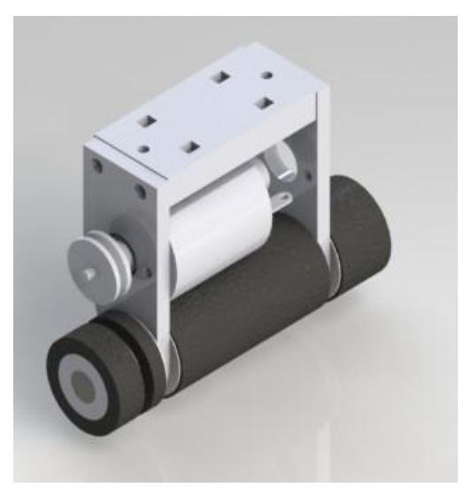
Our current dribbler iteration from 2011 is a total redesign from previous years, however still has some serious design flaws that have prevented it from being used in any matches. The design is ambitious in that it attempts to utilize all of the area in the front of the robot in between the omniwheels as a capture area for the ball. Unfortunately, misreading the motor datasheet led to our subteam utilizing a 24V motor in a 12V system, which meant our dribbler module was severely underpowered and was barely able to turn at all. The mechanical subteam plans to focus on iterating this design in spring of 2012.
3. Electrical
3.1 Redesign of Brushless Motor Boards
We had to redesign the brushless boards to address several problems we noticed in last year's international competition in Turkey. The first was that after driving for some time, the robots would drive erratically and not follow paths due to the MOSFET driver giving faults. We have replaced it with a new MOSFET driver that has a lower voltage limit. We have also introduced a better PCB layout.
The second problem was that the robots would miss some wheel speed commands. As a result, the wheels would occasionally spin continuously. We probed the signal going to the boards and ruled out bit errors over the air. The most likely cause is that the PIC is missing interrupts, so we replaced it with one that runs at 40 MHz instead of 2 MHz. An added benefit is that we can now send wheel speed commands more rapidly, making the robot's motion smoother.
Finally, the motors would stop working because of bad hall sensors. The sensors would physically fall off the motor. We believe that the robot's erratic movements due to the faulting of the old brushless boards caused the hall sensors to be torn off. The redesign of the boards should address this issue.
To summarize, the boards now have four layers, an Intersil 4086 3-phase MOSFET driver with a lower voltage limit of 7V, a dsPIC33FJ32MC304 PIC microcontroller that runs twenty times faster than the old PIC, MOSFET drivers that are rated for higher current and power, and 2220 size 100μF ceramic caps for decoupling.
3.2 Break Beam Sensors
We encountered a number of problems with the break beam sensors at the international competition in Turkey last year. For that competition we had just revamped the break beam sensor system to incorporate a more advanced sensor that included an infrared emitter and receiver in one ASIC. The smaller size of the break beam sensor compared to previous generations of sensors allowed us to place it underneath the kicker in a perspective to look directly at the ball. We had thought that the more advanced signal processing in the ASIC would give us the advantage of fewer false triggers and faster response time compared to the standard design with a separate emitter and receiver.
We were faced with two major problems in competition, however. Most importantly, because the break beam sensor was in one piece, its detection region was a circular area in front of the robot. This meant that there were locations that the ball could be near the corners of the kicking zone in which the break beam sensor would not trigger. In addition, depending on where the break beam sensor was positioned with respect to the front of the robot, the sensor would trigger when the ball was at different locations in front of the robot kicker. Thus, much of the time, the ball would be too far from or too close to the robot to be kicked properly.
The second major problem was the buildup of green fuzz from the field material on the break beam sensors. The fuzz ripped up from the field due to the wheels gripping the field accumulated in front of the break beam sensor and obstructed its vision, further making kicking difficult.
Due to these two major problems, we decided to revert to the old separate emitter and receiver design for this year. We chose higher quality parts and made some adjustments to the firmware to achieve lower false positives and more accurate response.
4 Software Improvements
4.1 Extended playbook
In the prior year, we rigidified the abstraction of strategies into skills, tactics and plays. We used this abstraction to develop a set of different strategies, so that we can have an extensive playbook that can be used in simulation for evaluating different outcomes. In addition to our simple and robust regular strategy, we created two additional ones that can be used as adversaries. We'll discuss some of their interesting features:
4.1.1 Synchronized actions
One of our new test strategies relies heavily on synchronized robot actions for offense. We use two simple primitives – passing and deflection shots on target. Of these, deflections shots are the simpler primitive – a friendly robot positions itself near the enemy goal, and the robot with ball possession shoots directly in its direction, at an angle such that scoring is most likely after a deflection from the stationary robot. We carefully characterized deflection angles from our robots, which resulted in several mechanical improvements to strengthen the shields for more predictable performance. Even after this, deflection success rates in our system are still too low to be used regularly in situations, other than the most desperate. Passes require a higher level of synchronization – the receiving robot has to be not only positioned, but also oriented correctly to receive the pass. We introduced such synchronization to a test strategy and tested it extensively in simulation. Because controlling kick strengths on our robots was not precise enough, we were not yet able to experiment with passes in the real world and fit our simulator models accordingly.
4.1.2 Zone-based strategy
We have also experimented with a different robot allocation in terms of strategy. Instead of explicitly assigning robots to offense or defense, we tried assigning different zones to robots and allowing them to switch between defense and offense. The three zones – center, left and right – were inspired by actual soccer. We have experimented with different algorithms for switching a robot between defense and offense in this case. Most of them were based on ball position and possession by our team / the enemy. However, such heuristics did not prove useful both in simulation and real play because of the delay between switching from offense to defense, which often left our goal not well-protected. We are looking into ways to improve those heuristics that would allow us to not dismiss such a zone-based strategy.
4.2 Monitoring infrastructure
In order to compare the different strategies we created, we need detailed metrics that evaluate different aspects of individual plays and tactics. Obviously, final game score is one such metric, but it is too coarse-grained to be used to draw conclusions on, for example, goalie performance. We have set a broad infrastructure throughout different aspects of our system that allows us to capture such metrics. We are in the process of identifying the relevant metrics for different plays. Possible candidates are: ball possession and shots on goal for offensive plays, saved shots on goal for goalie tactics, successful kicks/passes for a kicking or passing tactics, etc.
We have also added another lower layer of monitoring infrastructure that allows us to pinpoint reasons for failure of various components. This layer focuses on hardware characteristics – battery charge, voltage at the kicker capacitors, individual wheel speeds, etc., which are send over a two-way radio connection. Using such information has proved useful in debugging our system. For example, it allowed us to observe that slow charging of the kicker capacitors was causing a large number of failed kicks – an issue that, once identified, is fixed easily by per-charging the capacitors.
4.3 Motion planning
For motion planning, the primary contribution was an RRT (Rapidly-exploring Random Tree) planner [1], replacing the previous TangentBug planner . Over the years, we had made a few other attempts at implementing an RRT-based motion planner, but none of them were fast or robust enough to replace a simple TangentBug implementation. The current iteration has passed our robustness criteria and is currently our default motion planner.
The main change we introduced in the current iteration was to model the physical limitations of the robot when trying to come up with a path to follow. We introduced a simple model of maximum velocity and acceleration that was tuned to the physical realities of our robots. We use that model at every RRT expansion step and only expand towards a point if we believe the robot can follow the resulting path. This eliminates path jaggedness to an extent that there is no need for a later path smoothing step. We also bias path expansion towards the direction of the robot's velocity to add further hysteresis and decrease rapid direction switching.
Furthermore, in the implementation of our new motion planner, we made a few key observations that allowed us to create a computationally tractable algorithm:
- On the field, there are usually only a few obstacles immediately in the way (0,1, or 2).
- Everything is moving, so planning around distant obstacles is not useful.
- RRTs give different answers of varying quality each time they are run.
Based on these observations, we (1) always check direct paths before doing RRT expansion; (2) cut off path planning once expansion reaches a certain predefined radius; (3) run the algorithm multiple times at each time step and choose the best one based on a simple distance heuristic. Furthermore, in terms of RRT implementation, we use recursive k-d trees that partition the 2D space in hierarchical chunks, allowing us to reduce the computational intensity of collision checking.

5. Acknowledgements
We could not have made it this far without the support of our sponsors: School of Engineering and Applied Sciences at Harvard University and the Edgerton Center at the Massachusetts Institute of Technology. We would also like to give special thanks to Radhika Nagpal and Dr. Marie Dahleh of Harvard University and Stephen Banzeart of the Edgerton Center at MIT.
References
[1] Improving motion planning algorithms by efficient nearest-neighbor searching. A. Yershova and S. M. LaValle. IEEE Transactions on Robotics, 23(1):151--157, February 2007