RoboDragons 2012 Extended Team Description
Kotaro Yasui, Taro Inagaki, Hajime Sawaguchi, Yuji Nunome, Hiroaki Sasai, Yuki Tsunoda, Shinya Matsuoka, Naoto Kawajiri, Togo Sato, Kazuhito Murakami, Tadashi Naruse
Aichi Prefectural University, Nagakute city, Aichi, 480-1198 JAPAN
Abstract This paper describes a system configuration of RoboDragons, which is a team of Aichi-Prefectural University in Japan. This year, we concentrate on the software development. Main technical improvements include the algorithms of a mark defense strategy and a way how robot follow the moving ball in the offense strategy.
1 Introduction
In the team description paper (TDP) of RoboDragons2012, we briefly stated the overview of hardware and software architecture of our team and then described in detail about the new software development this year.
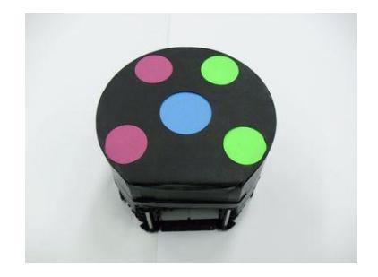
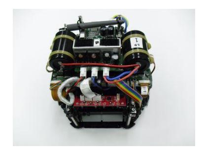
For the hardware, our current robots are the fifth generation ones in our Labs. Our teams have six robots at total. Each robot mainly consists of control unit, voltage booster, motors, wheels, dribbling device, IR sensors, kick devices, and communication device.
For the software, the base of our system is originated from the one at the time when we made a joint team with CMU in 2004 and 2005. Since 2005, many functions are added and improvements are accomplished. Then, this year, we present the algorithms of marking a opponent robot in the defense strategy and following the dynamic ball in the offense strategy.
In the extended team description (ETDP), we add the following descriptions into the TDP.
- A detailed description of soccer module (Sec. 3.1),
- Expressions of unknown variables in Sec. 5,
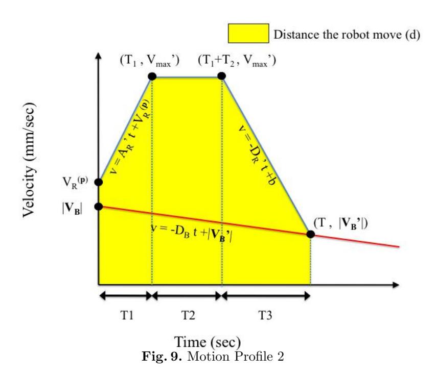
- Description of a method of making the motion profile for the case of saturated velocity.
2 Hardware Architecture
In this section, we show the features of our robot. All devices attached to the robot are described as below.
- a cylinder with dimensions of 145 mm height and 178 mm diameter
- the maximum percentage of ball coverage : about 18%
Robot Hardware Components
| Device | Description |
|---|---|
| Control Unit | CPU: Hitachi's SH2A processor with FPGA |
| Voltage Booster | convert from 15V DC to 150V ~ 200V DC; condenser has a capacity of 4500 µ; charging time is about 2 sec (output voltage: 200V) |
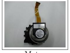
| Motor | "EC 45 flat 30 W" by Maxon; gear reduction ratio between motor and omni-wheel is 21:64 |
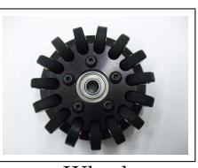
| Wheel | 4 omni-wheels, each has 15 small tires in circumference; diameter: omni-wheel(56mm), small tire(13mm); dribble roller: 20mm in diameter and 73mm in length |
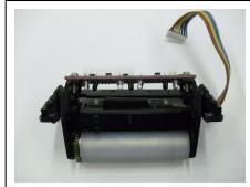
| Dribble Device (dribble roller and motor) | made of alminum shaft with silicon rubber; motor: "EC 16 15W" by Maxon; gear reduction ratio between motor and roller is 1:5.4 |
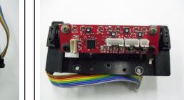
| IR Sensor | 3 pairs with infra-red light emission diodes and photo diodes; irradiation angle of the light is about 15 degree |
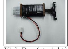
| Kick Bar | made of a solenoid and 7075 alminum alloy; solenoid: a coil winding a 0.6 mmϕ enameled wire; (Straight) propel a ball with 11.2m/sec at maximum; (Chip) fly a ball with 2m distance and 1m height at maximum |
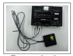
| Communication Device | modem : "FRH-SD07T" by Futaba (2.4GHz Spread Spectrum) |
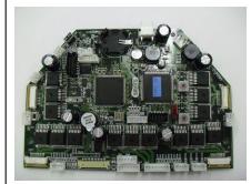
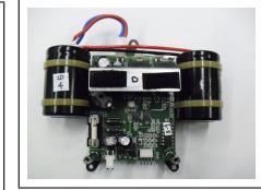
Data/signal flow
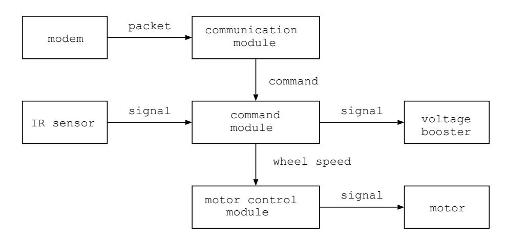
This is a data/signal flow of a control program on the hardware. The description is written in RoboDragons 2010 TDP.
3 Software Architecture
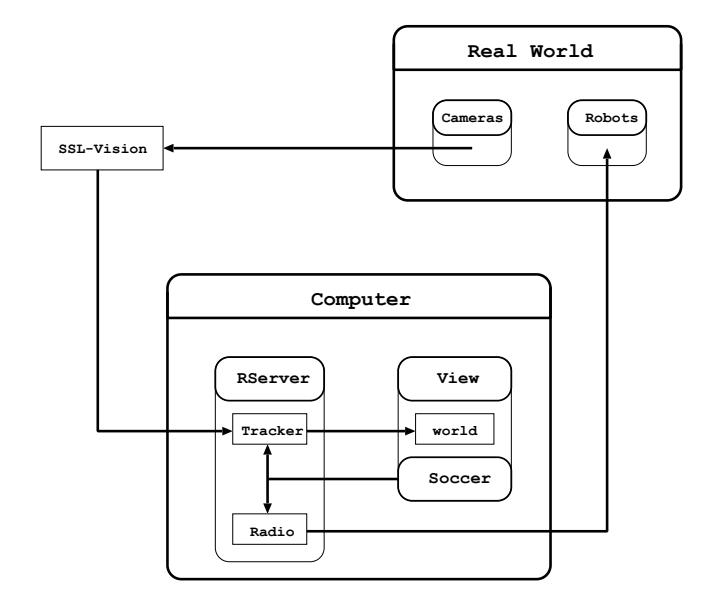
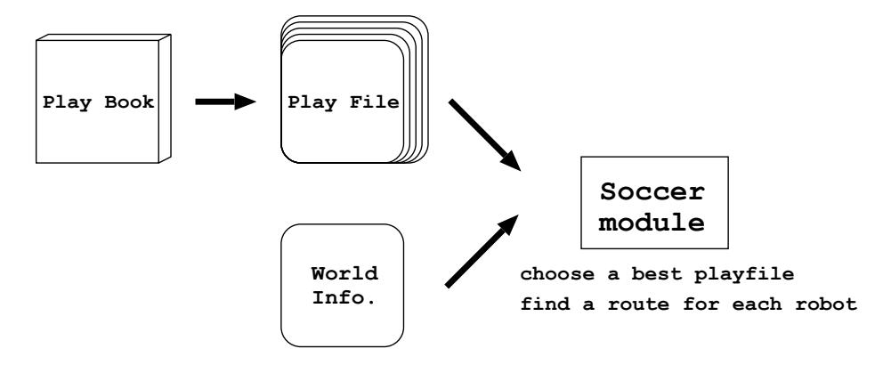
In this section, we show how our software architecture is composed and relates to the information from real world. The overview of our software system is shown as a diagram below.
3.1 Soccer Module
A soccer module is used to make an action command for each robot. In order to make a role, many patterns of strategies are needed to be compared from a field condition. Then a soccer module decides a best strategy matched in the game at the time. This is a movement of the soccer module to choose a best strategy.
4 Mark Defense Strategy
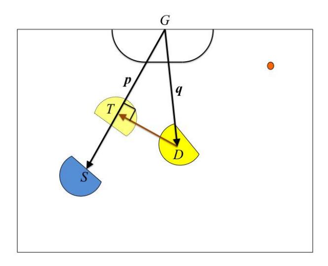
A mark defense strategy is used to defense a goal from a shoot robot in a set play. We have two kinds of tactics to exploit its strategy; one(ShootCut) is to prevent the goal by locating a mark defense robot on the shoot path, and the other(PassCut) is to intercept the ball on the pass.
4.1 Algorithm of ShootCut
- allocate a defense robot to each shooting robot
- process to mark a shooting robot $R^S$ by the corresponding defense robot $R^D$
- $S$: a coordinate on the position kicked by $R^S$
- $G$: a coordinate on the mid point of our goal
- $D$: a coordinate on the center position of $R^D$
- (a) calculate the equation (1)
$$T = \frac{\boldsymbol{p} \cdot \boldsymbol{q}}{|\boldsymbol{p}|^2} \cdot \boldsymbol{p} + G \tag{1}$$
(b) if $|\overrightarrow{GS}| < |\overrightarrow{GT}|$, then $T \leftarrow S$
4.2 Algorithm of PassCut
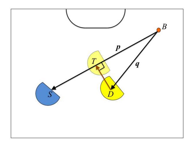
The algorithm of PassCut is almost as same as ShootCut, but change $G$ to $B$, where $B$ is a center coordinate of ball location. After the calculated equation (1) is shown as a diagram below.
5 The algorithm of a robot following a ball in dynamic offset
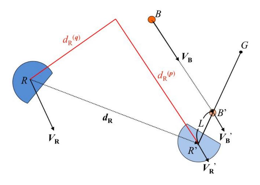
Definition of the variables shown as below:
B: a coordinate on the present ball position
R: a coordinate on the present robot position
$V_B$: a vector of the present ball velocity
$V_R$: a vector of the present robot velocity
G: a coordinate on the shooting target position
L: an offset length which is not to hit the ball
(the less distance between B and R, the less length of L)
$D_B$: a constant ball decceleration, which takes account of a friction
$V_{max}$: a max velocity of the robot
$A_R$: a max acceleration of the robot
$D_R$: a max decceleration of the robot
Let make an assumption that a robot can reach the ball in T second.
$\boldsymbol{V_B'}$: a vector of the ball velocity after T second
$$\boldsymbol{V_B'} = \boldsymbol{V_B} - D_B T \frac{\boldsymbol{V_B}}{|\boldsymbol{V_B}|}$$
$V_{\mathbf{R}}'$: a vector of the robot velocity after T second
$B'$: a coordinate on the ball position after T sec
$$B' = \frac{1}{2}(\mathbf{V_B} + \mathbf{V_B'})T + B$$
$R'$: a coordinate on the robot position after T second
$$R' = \frac{\overrightarrow{GB'}}{|\overrightarrow{GB'}|} \cdot L + B'$$
$\boldsymbol{p}$: a unit vector of $V_B$ $(\frac{V_B}{|V_B|})$
$\boldsymbol{q}$: a vector of rotating $\boldsymbol{p}$ by $\pi/2$ (rad) on counter-clockwise
when $\mathbf{p} = (p_1, p_2), \quad \mathbf{q} = (-p_2, p_1)$
$d_R$: a vector from R to R'
The subscript $(p), (q)$ on the right top of $V_R, V_R', d_R$ is a component of the vector p and vector q of $V_R, V_R', d_R$ respectively.
5.1 Explanation of the algorithm
In order to move the robot toward $R'$, we desolve the robot velocity vector into components of a vector $\boldsymbol{p}$ and $\boldsymbol{q}$ directions.
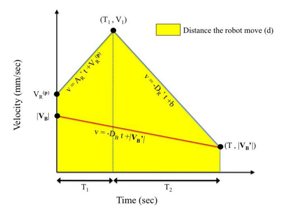
the component of p: control the robot velocity by making a motion profile as $V_R^{(p)}$ to be $|V_B'|$ when the robot moved $d_R^{(p)}$. (step(3)) the component of q: control the robot velocity by making a motion profile as $V_R^{(q)}$ to be 0 when the robot moved $d_R^{(q)}$. (step(4))
From the information so far, if T is given, we can make a motion profile of the robot for $\boldsymbol{p}$ and $\boldsymbol{q}$ directions in turn, because we can calculate $B'$, $R'$, $\boldsymbol{d}_R$, $d_R^{(p)}$, and $d_R^{(q)}$ one after another. On the contrary, if the motion profile of the robot for a direction $\boldsymbol{p}$ is made, we can calculate T. Therefore, we suggest the method, which calculates T and makes a motion profile for the direction $\boldsymbol{p}$ at the same time.
5.2 A method of making the motion profile for the direction p
Due to limitations of spaces, we assume the precondition below.
$${d_{R}^{(p)} \ge d_R^{(q)}} \land {V_R^{(p)} \ge |V_B|}$$
Make a motion profile shown as a figure below.
5.3 A method of making the motion profile for the direction q
From step(3), the time when the robot can reach the ball (T) is calculated, so a robot position willing to move after T second (R') can be calculated by step(1). Then from R', a distance between R and R' for a q direction $(d_{R}^{(q)})$ can be calculated. Therefore, we can make a motion profile as $V_{R}^{(q)}$ to be 0 when the robot moved $d_{R}^{(q)}$. To make the motion profile, we use the maximum acceleration of the robot as $A_R'$, the maximum decceleration of the robot as $V_{max}'$.
5.4 A robot velocity after sending frame period from step(3) and (4)
From step(3) and (4), a motion profile for each direction of $\boldsymbol{p}$ and $\boldsymbol{q}$ is provided. Then what we want to do is to calculate a robot velocity after sending frame period $(\boldsymbol{V_{RS}})$ in order to move the robot toward R'. To do so, look for the corresponding robot velocity for each direction where t= sending frame period from the motion profile. We call the robot velocity searched for $\boldsymbol{p}$ direction as $V_{RS}^{(\boldsymbol{p})}$, $\boldsymbol{q}$ direction as $V_{RS}^{(\boldsymbol{q})}$. Then, send to the robot for a vector $\boldsymbol{V_{RS}} = V_{RS}^{(\boldsymbol{p})} \cdot \boldsymbol{p} + V_{RS}^{(\boldsymbol{q})} \cdot \boldsymbol{q}$.
6 Conclusion
In this paper, we described our hardware and software architecture. This year, especially, we try to improve the software strategy: the algorithms of marking the opponent robot in defense and following the dynamic ball in offense. From this algorithms, we think the marking defense in set play and the offense without set play will improve in the game.
7 acknowledgement
This work was supported by the cheif director's special study fund of Aichi Prefectural University and the president's special study fund of Aichi Prefectural University.
References
- "Newton's Method" http://www.math.montana.edu/frankw/ccp/calculus/numerical/newton/learn.htm
- Akeru Ishikawa, Takashi Sakai, Jousuke Nagai, Taro Inagaki, Hajime Sawaguchi, Yuji Nunome, Kazuhito Murakami and Tadashi Naruse "RoboDragons 2010 Team Description", 2010
- Taro Inagaki, Hajime Sawaguchi, Akeru Ishikawa, Kotaro Yasui, Tomomi Yasui, Yuji Nunome, Kazuhito Murakami and Tadashi Naruse "RoboDragons 2011 Team Description", 2011