RoboFEI 2012 Team Description Paper
Felipe Fill Cardoso, Eduardo M. Nottolini, Vitor Hugo Beck, Rodolpho L. Felizatti, Felipe Camargo, Erivelton G. dos Santos, Feliphe G. Galiza, Victor Torres, Milton Cortez, José Angelo Gurzoni Jr., Reinaldo A. C. Bianchi, Flavio Tonidandel
Robotics and Artificial Intelligence Laboratory Centro Universitário da FEI, São Bernardo do Campo, Brazil
Abstract This paper presents the description of the RoboFEI Small Size League team as it stands for the RoboCup 2012 in Mexico City. The paper contains descriptions of the mechanical, electrical and software modules, designed to enable the robots to achieve playing soccer capabilities in the dynamic environment of the RoboCup Small Size League.
Introduction
RoboFEI team intends to use on RoboCup 2012 the same electronic board designs used in the last two years, which are provenly reliable, with the only change being the radio communication module. The Mechanical design received changes to improve its robustness to impacts and collisions and to improve its dribbling system. The scheme used to connect the electronic boards onto the robot's mechanical frame was also revised, allowing simple plugging and removal, almost without cable handling. Important motion control elements were also reviewed, aiming at making the robots more resilient, while at same time agile.
On the software front, the cooperative team behavior architecture developed last year is still under active development. It is expected to be more reliable for the 2012 competition.
This paper describes the current hardware, the software modules which compose the strategy system of the team, including state predictors, the dynamic role selection method based on market economy and some research topics that will be experimented in RoboCup Mexico.
Electronic Design
RoboFEI electronics consist of two boards: the main board, responsible for all embedded computation and robot's motion control, and the Kicker board, that commands the kicking devices and its associated power electronics. These two boards are described in details in this section.
Main Board
The main board has a Xilinx Spartan 3 FPGA (X3CS400) responsible for performing all the logic and control functions. The FPGA features a Microblaze 7.1 IP core as micro controller, five brushless motor controller modules, besides the kicker board and sensory modules. Integration of all these functions in the same IC eliminates the difficulties related to the communication and synchronization of different micro controllers, while at same time reducing considerably the number of components on the board. The Xilinx Spartan 3, with its IP core operating at 50 MHz, also provides fast computation, because of its integrated hardware FPU (floating-point arithmetic unit). The embedded firmware is stored in a 256K words RAM memory connected to the FPGA, to ensure even complex firmwares can be loaded. The five brushless motor drivers are designed with the IRF7389 N-P complementary channel MOSFETs, an feature Allegro ACS712 current sensors. The reading of the ACS712 is made by a AD7928 Analog-to-Digital IC. The power to the main board and motors is provided by one LiPo battery of 3-cells (11.1V) and 2200 mAh capacity.
Last year, a Wi-Fi (IEEE 802.11b) module was intended to replace the previous radio, based on the Nordic nRF2401 IC. The replacement was made mainly due to problems caused by the limited signal strength of the old module (of 0 dBm). While the Wi-Fi module was easy to use and possessed high data throughput, it proved to be a bad choice. At the RoboCup 2011 competition venue, the module started to present severe latency issues, with average latency above 200 ms. This was a project oversight, as this characteristic is typical of the IEEE 802.11 radios when in spaces cluttered with many other 802.11 networks. The nRF2401A modules were placed back into operation, and for 2012 a new radio system is under development, with the Xbee Pro Series 1 transceiver.
Kicker Board
The kicker board, responsible for controlling both the shooting and chip kick devices. uses a boost circuit designed with the MC34063 IC. This IC produces a 100 KHz PWM signal to charge two 2700 µ F capacitors up to 200V. This IC controls the whole circuit, sparing the main-board's CPU from the need to generate the PWM signal and monitor the capacitor's charge. Last year, the kicker board design was slightly changed: The MOSFet transistors that releases current to the solenoids were replaced by the IRFSL4127. These MOSFet, on TO263 packages, replaced the previous, much bigger, IRF90N20, without any side-effect.
The kicker board features an independent power supply, fed by a 3-cell (11.1V), 800mAh, LiPo battery, and the connections between the kicker and main boards are all opto-coupled, to avoid spikes and eventual damage to sensitive electronic circuitry.
Mechanical Design
In compliance with the SSL rules, the height of the robot is 148 mm, the maximum percentage of ball coverage is 15% and the maximum projection of the robot on the ground is 146 mm.
The current mechanical design, as the previous ones, is essentially made of aluminum alloys of the 6000 series, due to its good hardness/weight relation. Exception are the more stressed parts, such as wheel axes and the small rollers of the omnidirectional wheel, that are made with stainless steel. Parts that are required to be light-weighted and to provide electrical isolation are made of Nylon. The total weight of the robot is 2.6 Kg.
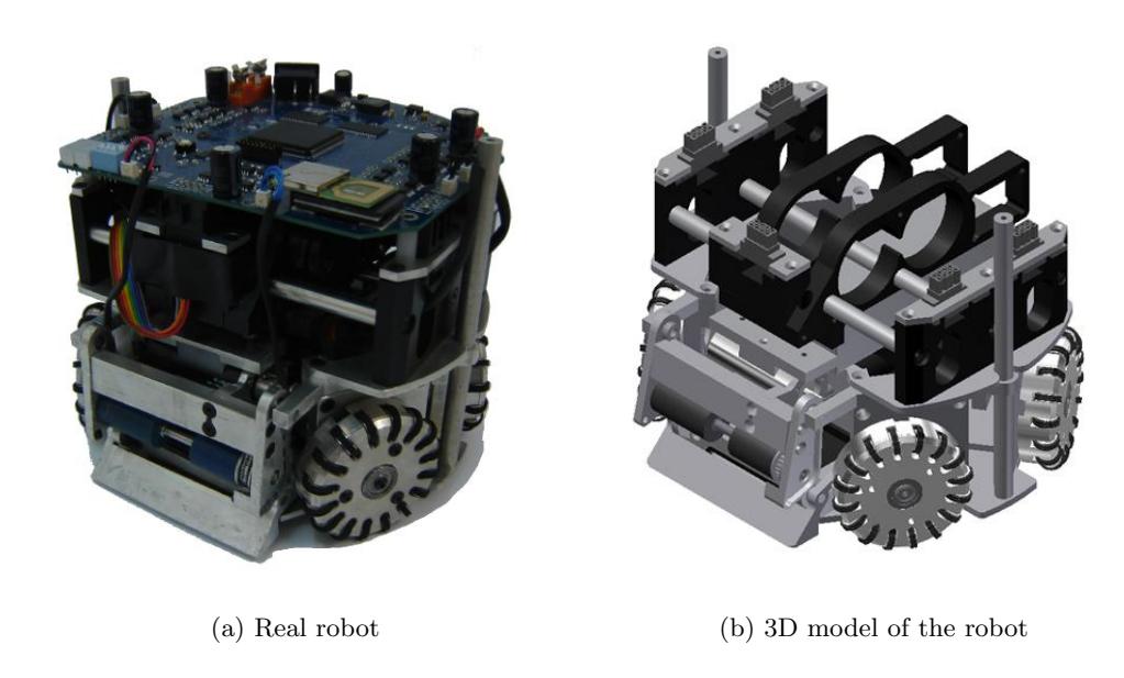
For this year, upper frame of the robot was modified, resulting in a very simple assembly scheme. The electronics main board is simply docked on its position, where its connectors mate with the connectors of the motors, already wired and assembled internally to the robot frame, in a similar way of the used in the auto industry. These connectors are Molex Microfit BMI headers and receptacles. The batteries also slid into their positions, within the plastic supports, easily accessible from the back of the robot. A general view of the robot can be seen on Fig. 1.
The motor used on the wheel is the Maxon EC-flat 45 50W. With 5200 RPM nominal speed and 84 mNm nominal torque, the EC-45 50W allows the robot to accelerating above 6 m/s² when using the 3:1 gear ratio. However, last year observation has shown that acceleration rates above 3.5 m/s² did not bring benefits, due mostly to wheel slippage. Moreover, on long term these high acceleration rates caused damage to the internal supports of the motor's stator, and several of them had to be repaired. This year, the motor driver firmware was modified to keep the torques bounded through the use of current controllers with Butterworth IIR low-pass filters on the feedback loop. Work is in progress to expand this current controllers to replace the motor motion controllers entirely.
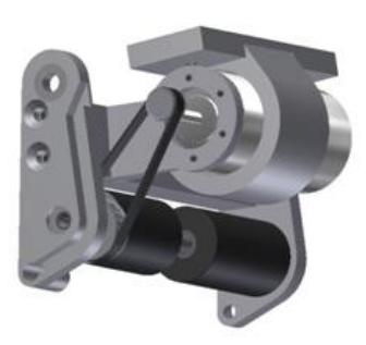
The dribbler device uses a Maxon EC-Max 22 25W motor which allows the roller device to have greater angular speed while maintaining the required torque. The dribbler and damper system was changed this year, with the replacement of the gears by a belt and pulley design. The belt and pulley present reduced tearing when subject to vibration and collisions and has easier adjusts. The pulley used is made of kevlar, ensuring its superior resistance. The new dribbler can be seen on Fig. 2.
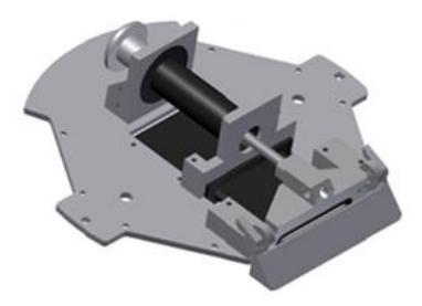
The Kick device is composed of a 30 mm diameter cylindrical solenoid made of nylon, coiled with AWG21 wires, with a plunger of 14 mm diameter made of SAE1020 steel. The chip-kick device consists of a rectangular solenoid mounted in front and below the kick device. Its nylon core cases a 3.75 mm width steel plunger. Both the kick and the chip devices can be seen, mounted on their positions on the lower plate of the robot, in Fig. 3.
Motion Control
The control system implemented in the RoboFEI team, shown in figure 4, is embedded into the robot's CPU, and uses wheel odometry as feedback sensors. Individual PI controllers are present in each wheel, responsible for making them to rotate at the commanded speed, and, interleaved with them, are two PID controllers responsible for the robot motion. The strategy module sends, via radio, the distance and direction of translation, the amount of rotation and the speed desired. The translation vector is given in polar coordinates, where ρ is the direction of the movement, relative to the robot's front, and r is the distance to be traveled. The rotation θ represents the angle the robot must turn on its center, also in relation to the robot's front, and the speed is given as percentage of the robot's maximum speed.
Once the robot receives this information, it uses the force and velocity coupling matrices to resolve the robot's movement into wheel movement. To close the control loop, the odometry information collected from the wheels is fed into the pseudo-inverse of these matrices (non-square matrices do not have inverses), and the output is then used as feedback for the translational and rotational controllers. More details about omnidirectional motion control can be found on [5], while the full implementation details of RoboFEI's controller appears on [4].
![Block diagram of the control loops embedded into the robots (image from [4]).](/tdps/soccer_smallsize__2012__RoboFEI/_page_5_Figure_0.jpeg)
Path Planning and Obstacle avoidance
The path planning and obstacle avoidance algorithm employed is based on the Rapid-Exploring Random Tree (RRT) with KD-Tree data structures, proposed by [1], and on the ERRT algorithm developed by [2], complemented by an algorithm to include preferred path heuristics and set the angle of approach. The algorithm based on RRT was chosen because (i) its capacity to efficiently explore large state spaces using randomization, (ii) the probabilistic completeness offered, (iii) its lookahead feature and (iv) the easiness of the algorithm's extension, when new constraints or heuristics are deemed necessary.
This section focuses on describing this add-on algorithm, which is implemented on top of the ERRT base algorithm.
The add-on algorithm has the function to set the angle which the robot approaches the ending point, as commanded by the strategy layer, an item that many path planners do not treat. It is not desirable, for example, that a robot going to the ball on the defensive field accidentally hits the ball in the direction of its own goal, or yet, that an attacking robot arrives at the ball in a position in between the ball and the opponent's goal. To create a path that conforms to the angle of approach requirement, a circular virtual obstacle centered on the ending point is created, with a 10° width circle segment and vertex at the desired angle removed. This effectively forces the path planner to create a path the reaches the ending point passing through this 10° opening. The radius of this obstacle-like constraint is set to a value close to half the size of a robot.
Market-Based Dynamic Role Selection
Since last year, development of a method to allow dynamic allocation of the role each robot executes is under development. The roles, such as fullback, defender, midfielder, striker, forward and attacker, are not tied to a particular robot (except the goalkeeper), and there is no limitation on how many instances of the same role can exist, what allows the selection mechanism of the robots to unrestrictedly create role combinations. This dynamic allocation method uses auctions to allow an autonomous strategy expert, the Coach module, to offer roles for the robots to perform during the game.
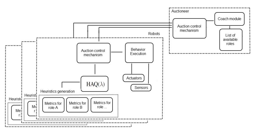
This Multi-Robot Task Allocation (MRTA) system, shown in Fig. 5, is based on the work by [3], and consists basically of the auctioning module, that uses first-price auctions as task allocation mechanism, and the Coach module, which monitors the game and selects which roles will be available for the robots to select. The Reinforcement Learning module present on [3] is not yet in use. This module would be instantiated in each robot and, through the use of the HAQ(λ) algorithm, would allow the robot to learn utility functions, or interests, toward bidding for each of the roles offered on the auction.
Market-based methods use the theory of market equilibrium, from economy. They are computationally efficient, and can be enhanced with machine learning algorithms in a simple manner, in the form of utility functions. However, the efficiency of market-based methods is only as good as these utility functions, used by the agent to reason about its aptitudes and interests. The creation of high-level reasoning algorithms that could serve as utility functions in robot soccer is a difficult task, due to the complexity and dynamism of the environment. Currently, the utility functions are hard-coded on the robots, but future work intends to augment the capabilities of the robots to evaluate their utilities and learn from experience or mined data.
The remainder of this section briefly describes the strategy module where the task allocation is performed, to help on its understanding, and a description of the auction mechanism used.
Strategy System
This MRTA system is implemented in a strategy module formed by three abstraction layers: primitives, skills and roles. The lowest layer has the primitives, that are simple actions like activating the kicking or dribbling devices, or the ball presence sensor. On top of this layer is the skills layer, that contains short duration actions which involve the use of one or more primitives and additional computation, such as speed estimation, forecasting of the positions of objects and measurement of the completion of primitive tasks. Passing the ball or aiming and shooting to the goal are examples of skills.
The top layer is the roles layer, which are created using combinations of skills and the logic required to coordinate their execution, and are intended to be executed for longer periods. The existent roles are fullback, defender, midfielder, striker, forward and attacker.
Auctioning Module
The Auctioning module is executed by the Coach agent, responsible for analyzing the game situation and defining, according to its reasoning of the conditions, what roles, and in how many instances, will be available for the robots to bid. At a certain stage of the match, for instance, the Coach can decide that the team should be more offensive, and then auction more offensive instances, like Strikers and Attackers, and only one instance of the Defender role. A note: the number of roles offered can be larger than the number of robots, so as to give to the robots more selection choices. The Coach also prioritizes the order in which the roles will be offered, starting by the offensive roles (Attacker, Striker) when the team is attacking and by the defensive roles otherwise.
The first-price auction algorithm works as follows:
- Auction announcement. The coach agent starts an auction, offering the role of highest priority available. A message is sent to the robots, informing about the open auction and the role being offered.
- Biddings formulation. Each robot evaluates its utility function and submits a bidding towards that role.
- Auction result. The coach defines the winner of the auctioned role and sends a message to the robots, informing them.
- Repetition. The process is repeated, without the winner robot and the previously auctioned role, until there are no more robots without tasks.
The interval between auctions has central importance to the auctioning system performance, so it has to be adjusted. The current implementation expresses this allocation as an instantaneous iterated allocation problem (see [6]) and the adjust of the interval is made empirically, however more investigation is to be done on methods for deciding when to perform a new auction.
Acknowledgments
We would like to thank, in advance, the Small Size League Committee, for the consideration of our material. We would like also to immensely thank the staff of Centro Universitário da FEI, for all the help we always received.
References
- Atramentov, A., LaValle, S.M.: Efficient nearest neighbor searching for motion planning. In: IEEE International Conference on Robotics and Automation. pp. 632–637 (2002)
- Bruce, J., Veloso, M.: Real-time randomized path planning for robot navigation. In: Proceedings of IROS-2002 (2002)
- Gurzoni Jr, J.A., Tonidandel, F., Bianchi, R.A.C.: Market-based dynamic task allocation using heuristically accelerated reinforcement learning. In: 15th Portuguese Conference on Artificial Intelligence (EPIA) (2011)
- Gurzoni Jr., J.A., Martins, M.F., Tonidandel, F., Bianchi, R.A.C.: On the construction of a robocup small size league team. Journal of the Brazilian Computer Society 17, 69–82 (2011), http://dx.doi.org/10.1007/s13173-011-0028-4
- Rojas, R., Förster, A.G.: Holonomic control of a robot with an omnidirectional drive. KI - Künstliche Intelligenz 20(2), 12–17 (2006), http://www.kuenstlicheintelligenz.de/
- Weigel, T., Auerbach, W., Dietl, M., Dumler, B., Gutmann, J.S., Marko, K., Muller, K., BernhardNebel, Thiee, B.S.M.: CS Freiburg: Doing the right thing in a group. In: Stone, P., Kraetzschmar, G., Balch, T. (eds.) RoboCup 2000. Springer (2001)