RoboJackets 2012 Team Description Paper
Alex Cunningham, Hunter Scott, Stefan Posey, Stoian Borissov, Nikolaus Mitchell, Eri Huang, Raymond Chian, Nicholas DePeri
Georgia Institute of Technology - Atlanta, Georgia, USA
Abstract For the 2012 RoboCup SSL season, the Georgia Tech RoboJackets team has updated the mechanical designs and improved the electronics that were outlined in the previous year's TDP. This year will see the new and preexisting fleet. Software robustness to hardware failure, traction control, and gameplay. The current robot fleet includes many incremental improvements over the 2011 design to address deficiencies in the previous design. This document describes our overall system, with a focus on the improved software system, new electrical design, and mechanical content not present in the 2011 TDP.
System and Team Overview
We divide the robot system into a three subsystems with a corresponding sub-team.
Mechanical designs and builds the physical robot chassis, drive components, kicking/chipping mechanisms, and mounting all of the electrical hardware within the robots. They are also responsible for engineering the placement of all components, both electrical and mechanical, within the robot.
Electrical designs and builds the control circuitry for the robots, the kicker solenoid system, and the radio communications modules.
Software handles control of the robots from the main computer, including world modeling, low-level control, and high-level strategy and planning.
While each subteam can work on a particular segment of the project, many zones necessitate significant collaboration between the subteams, such as accounting for electrical considerations in design of the kicker & chipper systems, or sensor integration relevant to control approaches. There are two main phases of development work: prototype design, validation testing, and monitoring. In prototype development, the mechanical and electrical teams collaborate to design, build and test the physical components of the system, and undergo design reviews from the rest of the team. Likewise, during validation testing, systems are assessed from a manufacturability and performance stand point both separately and as a fully integrated unit. Once a fully integrated unit is tested, construction on a new fleet may begin.
Following a production run, the fleet is monitored for longer term performance and reliability. Changes are made to modules or subsystems as needed. During all phases the software team works in parallel, using a combination of a simulator system, 2008 robot fleet, and the 2011 robot fleet to develop the necessary software to drive the robots for competition. By exploiting existing resources, the team can produce a robust software package ready in time for testing even during unplanned prolonged hardware downtime.
For 2012, our strategy is to improve on previous performance on three fronts. One significant undertaking is completing reliability upgrades on our 2011 fleet, which incorporates many of the lessons learned at competition. The new fleet design also includes the next iteration of our control electronics, which includes new sensing facilities, such as encoders and an IMU. Software has focused on building more robust motion control and reliable open-field gameplay. These improvements will combine to produce robots that are more capable and competitive than the previous design.
During our experience of making our 2011 fleet competition-ready, we added a number of small but useful features in software to compensate for hardware challenges. Due to the frequency of faults in both mechanical and electrical subsystems during competition, we added tracking of subsystem status to our logging and sensing system, and adapted plays to choose robots for roles based required capabilities. These subsystem faults include disabled kicker/chipper (due to either electrical or mechanical problems), ball sense wiring failures, and shut off motors (due to disconnected encoders, hall-effect sensors, or stalling).
With a detection facility in place for these failures, we redesigned plays as to what system requirements were necessary for choosing a particular robot for a role. The goal of these adaptations is to avoid problem scenarios, for example, the robot chosen to take a shot on goal has a disconnected kicker or broken ball sensor. While the redesign of our plays was relatively straightforward, this design requirement forced us to determine what the minimum requirements are for each role, which enables use of even partially broken robots in certain roles. Plays such as free kicks can now enforce that the robot performing the kick actually has a working kicker and will prioritize robots with fully functional encoders. These extra specifications has made play development over during preparation for the 2012 season easier, especially as we make hardware changes to the existing fleets.
Improved Play Design
Beyond the addition of requirements for choosing robot roles based on hardware capability, and the simplifications specified in the 2011 TDP [4], we are working to improve play design by focusing on a number of techniques:
- Kick/Chip Aim and Power Calculators: In previous years, we have experimented with optimization-based pass planning systems [4] but such systems were ineffective outside of simulation due to the movement and shooting precision of the real robots. To address this flaw, we are implementing a Kick/Chip Power Calculator. We are fitting simple curves to empirical measurements of Kicker/Chipper Power vs. Distance/Time so that we can project kicks and chips more accurately during passing plays, with the goal of kicking one-touch-pass shots.
- Open Defense: Several other teams have successfully implemented one-touch-pass shots, where the recipient of a pass immediately shoots upon the goal. In previous years, our defense system was capable of recognizing and intercepting open pass routes and open shots to goal; however, to better address such dynamic threats, we are designing integrated behaviors that will maximize goal coverage from multiple lines of attack.
- Ninja Goalie: The horizontal crossbar of the goal can obscure the goalie from view of the camera system. By maintaining estimates of robot position through internal sensors (cf. 2.3 Traction Control), the goalie will be fully operational even during the presence of visual artifacts.
Traction Control
One of the larger problems discovered while deploying the new fleet of robots in Istanbul was wheel slip problems that lead to poor low-level motion control of the robots. While the drivetrain is capable of higher speeds, it became necessary to slow the robots in software to ensure we could reliably drive in straight lines. The encoders added to the new robots provided significantly improved wheel-velocity control, but the overall velocity control could not compensate for individual wheel slippage.
The solution to this problem is to design a controller that can explicitly account for wheel slippage by maintaining traction coefficients µ = µfr µbr µbl µfl for each wheel and calculating reference wheel velocities that account for individual wheels with low traction. This controller will be able to achieve body velocities with even a small subset of wheels with traction, and we can simultaneously drive slipping wheels differently to try to regain traction.
While this is a relatively straightforward solution, estimating µ is difficult, particularly in the presence of latency in the control system when we try to incorporate the control computer and vision to perform this estimation. We can solve the estimation problem on board the robots, however, by incorporating the 6DoF IMU installed on all of the robots, as well as wheel load monitoring. The IMU provides two means to provide feedback control:
- Estimating Wheel Contact: Because pitch and roll determine which wheels are touching the ground, we can use these estimates to provide an initial estimate for µ.
- Estimating True Movement: To provide a feedback signal for the body velocity controller, we can integrate the inertial sensor data to determine the
We can fuse these measurements, along with motor load values, in a filter framework to allow the body velocity controller to account for wheel traction problems.
In addition to improving driving, we can exploit this additional estimation to provide better estimates for the position and velocity of the robots which could allow for position control to operate on the robots as well. While IMU drift and wheel slippage will corrupt the position and velocity estimate, we can zero the integration estimates whenever the robot is stationary and use aiding from global vision. As is frequently used with inertial navigation systems, which combine GPS with inertial sensing [1], we can substitute global vision for GPS. In an aiding framework, we can handle the latency from global vision correctly when combined with high-rate inertial sensing. This will allow our robots to perform accurate motion control, even when vision may be obscured momentarily.
Improved Simulator
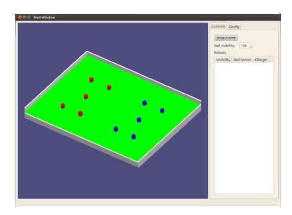
Because our previous simulator was based on Nvidia PhysX as a physics simulation, which has not been updated for Linux in recent years, we have moved over to using the Bullet physics engine, as described in our 2011 TDP [4]. While we were not finished with a fully usable simulator in time for the Istanbul competition, we have continued development, now with a full 3D visualization. A large part of this change has been to make the current state of the system comprehensible to current team members and make the simulator a more useful tool for robot development. As such, we have formulated a more well-realized plan for updating the simulator and integrating it into our design flow, with the following
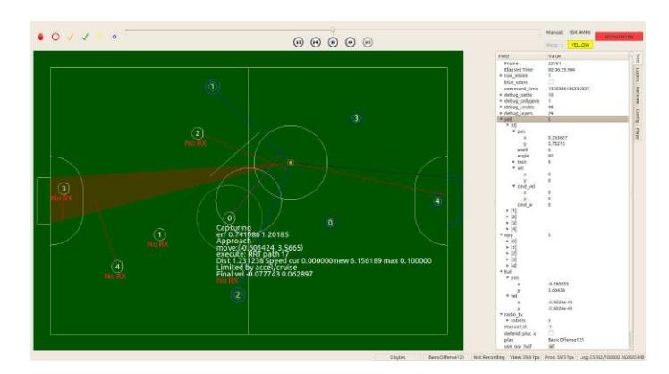
- Full visualization: necessary to debug cases when the 2D display in the soccer gameplay is insufficient, particularly when the ball or a robot gets into a hard-to-model state, such as a robot falling over and falling off of vision.
- Robot and ball occlusion: we can develop plays in the more realistic case we handle these cases. Basic ball occlusion existed in the previous simulator [2,3].
- Sidechannel communication with soccer gameplay: Because there is an estimation component in tracking the ball and managing the robot state, we will have a separate communication link between the simulator and soccer gameplay to allow for empirical comparisons between estimated ball positions and ground truth.
- Simulated Robot Firmware: We can use the simulator to help develop the firmware, particularly in such areas as on-board aided position estimate, which necessitates swappable firmware modes for robots.
Mechanical Design
Having finished our newest fleet for the 2011 Istanbul RoboCup event, this year the RoboJackets focused on improving existing mechanical assemblies to address hardware failures. These were encountered during the competition within the drive modules and kicking assembly (see [3,4] for details of these structures). For each of these problems a solution was drawn up in order minimize future fault and ensure maintenance requirements could be kept to a minimum. These issues were overcome by a combination of both modifying our assembly process and when necessary modifying our designs.
Drive Module Upgrades
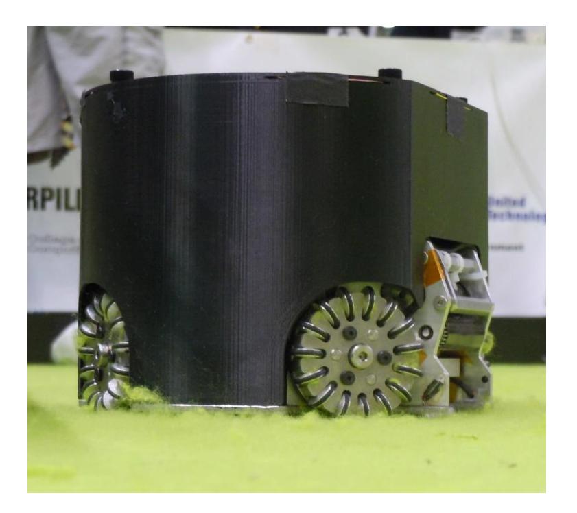
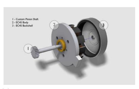
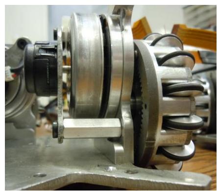
Both during and after competition, we investigated the operating state of the modules. For reference, see Fig. 3a for an illustration of our motor modules and Fig. 3b for the installed motor module. We identified the following problems:
- Back shell separation from modified drive motors
- Separation of encoder from mount plate
- Loosening of omni spacer
Back shell separation had multiple factors. Initially the motors were assembled with a retaining compound that cured in absence of oxygen. This was insufficient for holding the back shells onto the pinion shafts and over time the backshells would loosen. Some form of additional compound is needed due to slight deformations that the shells encounter during motor disassembly and tolerance issues with custom shafts. Additionally, the zip ties holding the encoder wires moved and started rubbing against the back shells. This rubbing pulled the shells off of the shafts. To increase clearance, we rerouted the encoder wires with tape. During this modification, we observed that some of the encoder wires had been zip-tied down in a manner that put too much stress on the encoders, which lead to a few incidents of connector failure and encoder separation from the mounting plate.
With the drive modules, omni spacers were loosening during omni wheel removal for maintenance. This was a design pitfall identified before initial production, but was viewed as an accepted issue. We identified that having reverse robots could result in confusion during maintenance during competition.
Kicker Redesign
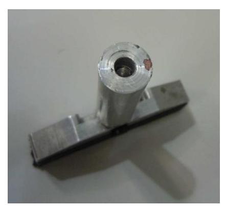
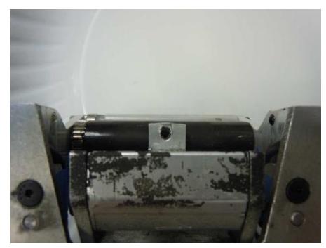
The bimetallic plunger designed for the 2011 fleet, failed mechanically during competition in the summer of 2011. After repeated kicking, the forward aluminum portion of the plunger deformed plastically in two locations. The first location of failure was the connection between the kicker boot and the plunger, and is shown in Fig. 4a. At the apex of the kick, the forward momentum of the kicker boot pulled the 6-32 screw, that connects the boot and plunger, forward causing deformation in the aluminum half of the plunger. The second location of failure was the interface between the steel and aluminum portions of the kicker plunger, and can be seen in Fig. 4b. The two halves of the plunger were held together with an 8-32 threaded stud. The forward momentum of the aluminum half of the plunger caused the 8-32 stud, to rip out the threads in the aluminum portion of the plunger.
In order to address these failures, we switched the material for the forward half of the plunger to 304 Annealed stainless steel. Stainless steel provides the same magnetic properties as aluminum, but it will not shear after undergoing multiple high power kicks. We expect a reduction in kicking performance due to the greater density of steel over aluminum. The reduction in the maximum allowed kicking speed from 10m/s to 8 m/s will allow us to use the new plunger design and still achieve maximum kicking velocity without a need for changes to electronics or software components.
Developments Toward New Dribbler
In order to improve ball control, and prevent the ball from bouncing on the robot's dribbler, we are replacing the fixed dribbler arms with passively damped arms. The goal of the damping system it to absorb the translational energy of the ball and transform it into mechanical energy which deforms a spring. The new dribbler design will feature an actuating set of arms each attached to a torsion spring. In order to prevent prolonged oscillation of the ball's position following contact with the dribbler, we will make the the the dribbler system critically damped.
In order to achieve critical damping, we will test springs with different spring constants. Because the frequency of oscillation of the coupled ball and dribbler system will depend on the velocity of the incoming ball, the dribbler will be tested with different incoming ball velocities. In our test setup, one of our robots, will kick the ball at varying speeds towards a receiving robot that has a damped dribbler. The ball will pass through a speed gate in order to calculate its exact velocity. Each of the springs tested will be rated by how long it takes for the ball and dribbler to achieve steady state, with the goal being to minimize the amount of time it takes to achieve steady state. We will perform the test on multiple different kinds of carpet, since every carpet has a different coefficient of friction, which influence how the ball behaves once captured by the dribbler. If after the tests, we conclude that carpet finish has a large impact on dribbler damping, we might consider a modular damper design that would allow us to change out springs depending on the kind of carpet we encounter.
Electrical Design
This year we have made several changes and improvements over last year's electronics on our robots. The 2011 fleet represented a major design upgrade for electronics and these improvements were used to retrofit our 2008 fleet. This year, among other tweaks, we changed the design of our kicker control electronics in response to the maximum ball speed rule change and to remedy problems encountered last year.
Antenna Updates
For our 2008 robot fleet, we designed and constructed a 900MHz halo antenna. A halo antenna is a ring of heavy-gauge wire with the feedline's ground attached at one point and a gap directly opposite this point. A gamma match arm made of smaller wire leads from a capacitor at the feedline to a point further around the ring. This antenna provides coverage in a plane similar to a dipole but with minimal height. The antennas were made from bent solid copper wire and required individual tuning after installation in the robot. This antenna design is very sensitive to variations in dimensions, which resulted in significant variation in performance between antennas. To reduce the time required to tune each antenna and to make the antennas similar in bandwidth and return loss, we produced new printed halo antennas. These new antennas are normal printed circuit boards on FR4 material. The printed pattern has dimensions similar to the original halo. While our original halo design required two adjustments, one trimmer capacitor at the feedpoint and one sliding copper plate near the gap, the new antennas require only the feedpoint adjustment.
Since the antenna is sensitive to any nearby metal objects, the antenna is mounted on standoffs near the top of the robot and the connector used to feed it is a right-angle MMCX connector on the edge of the board. This choice of connector eases assembly and keeps the coaxial cable away from the antenna except at the feedpoint. We continue to use the Texas Instruments CC1101 single-chip radio, but with a ceramic balun/filter to replace the numerous capacitors and inductors we used previously. The radio protocol has been changed to allow more data to be transferred between the control computer and the robots. All robots are now able to report their status (such as ball possession and diagnostic data) at 60Hz. The protocol is time-multiplexed half duplex: the control computer sends one packet containing commands for all six robots on a team, and each robot is assigned a time slot in which to send its response. On power-up or loss of signal, each robot scans a preprogrammed list of frequencies looking for a valid command with its ID. To support development of on-board navigation, robot firmware can be updated over the air on all robots simultaneously.
Microcontroller and Firmware
We previously switched from the NXP LPC2103 microcontroller to the Atmel AT91SAM7S64. The new microcontroller provided more memory, the option to increase memory while maintaining footprint compatibility, and a USB device interface. When connected by USB to a development computer, the robot appears as a serial class device and presents a command-line based interface for diagnostics, testing, and programming. No special drivers are required to communicate with the robot. While a JTAG interface is still present for debugging, both CPU and FPGA firmware can be programmed over USB without a JTAG adapter. The USB interface can be used to test all robot hardware without any radio activity, for example to allow robot repairs without interfering with an ongoing game. This year, the firmware that supports the command-line debugging interface was improved to include support for more tests and diagnostics.
Sensors
Our design incorporates several unique sensors to maintain a reliable estimate of the state of the robots and the game. The sensor suite includes both optical and hall effect shaft encoders, a MEMS inertial measurement unit, and an optical sensor for ball detection.
Each drive wheel has an encoder which produces 1440 ticks per revolution, resulting in a distance resolution on the ground of approximately 24 µm. The wheel encoders are used for closed-loop speed control of each wheel. A hall effect current sensor is placed in series with each motor's drive circuitry to allow measurement of the average current to each wheel. By measuring battery voltage, motor current, and motor speed, we can estimate the load on each motor and detect wheel slippage. Our goal is to optimize point-to-point motion to achieve maximum acceleration without losing positional accuracy due to slippage.
A six-degree-of-freedom inertial measurement unit (IMU) composed of an Invensense IMU-3000 gyroscope and an Analog Devices ADXL345 accelerometer allows the robot to sense its movement independently of vision. If the robot leaves the cameras' field of view, the IMU may be able to maintain a sufficiently accurate position estimate to allow it to move back on to the field. We are attempting to use the IMU to improve the robot's pose estimate to allow for more precise motion control. Our plan for future development is to move pose estimation and low-level motion control onto the robots to minimize latency and to allow us to take advantage of the IMU's motion estimates.
As in previous years, we detect ball possession with a break-beam sensor under the dribbler bar. This sensor consists of an infrared LED and a phototransistor. Previously, this sensor was frequently broken by contact with other robots because the sensors must be in an exposed location. A failure of the ball sensor gave the same indication as ball possession, requiring heuristics on the control computer to determine whether a particular robot's ball sensor was damaged. The new mechanical design better protects the sensors. The new electronics can detect four classes of ball sensor failure: LED open, detector open, detector shorted, and dazzling (excessive ambient light). If the LED or detector is mechanically damaged, the most likely result is an open circuit which can be detected and reported, allowing the robot not to be chosen for ball-handling tasks during gameplay and to be replaced at the next opportunity. To compensate for varying ambient light, alternating measurements are made with the LED on and off. If the LED-on measurement is unexpectedly high, the most likely cause is excessive ambient light, and the ball sensor will not report constant possession. By detecting ball sensor failure, we can avoid certain cases where a robot attempts to handle a ball that it does not actually possess.
Kicker Control Electronics
Two solenoids are used for ball handling: one for kicking forward and one for chip-kicking upwards. In 2011, each solenoid was operated by discharging a pair of capacitors through an IGBT into the solenoid coil. The 2011 kicker allowed for improved control parameters. Kick strength can now be determined by the length of the current pulse into the solenoid. This current can be regulated to an adjustable value, allowing longer pulses with more carefully controlled current. This also allows the maximum current to be restricted to a value that will not damage the IGBT even with a shorted coil. The current limit is implemented by measuring the coil current with a hall effect current sensor (Allegro ACS758) and switching limit minus a small hysteresis value, the IGBT is turned back on. The robot can record coil current and capacitor voltage traces during a kick for later analysis to facilitate kicker solenoid and electronics development.
This year, the RoboCup SSL rules were changed to put a limit on ball speed. Previously, we were capable of kicking the ball in excess of 12 m/s. The new cap limits speed to 8 m/s, so the new kicker design is in part a response to this. By using more and smaller capacitors, we can prevent wasting weight, space, and money on larger capacitors that are now unnecessary. The 2012 kicker has a similar form factor to our 2008 kickers, with several 250V, 820 µF capacitors lying horizontally. This saves significant space around the wheel base and allows the mechanical design to have more flexibility in dribbler size and wheel spacing.
Previous kicker boards were all electrically isolated for safety reasons. Unfortunately, this resulted in a higher level of complexity and more potential failure points. It also prevented full electrical shielding on the PCB. After consideration, the decision was made to abandon isolation in favor of a new design, while maintaining safety. A flyback topology with the LT3757 was used for several reasons. We wanted to maintain charge on the capacitors, continue charging the capacitors even if they were close to their target voltage, and gracefully handle the short circuit current load condition that occurs when the capacitors are empty. The flyback regulator was implemented using the same transformer that was utilized in a previous design iteration because of it's proven reliability and our existing inventory. To provide additional safety, a red LED was added to the kicker along with a discharge switch. If the red LED is on, team members know that the capacitors are charged and the board is potentially dangerous. By pressing the discharge button, all remaining energy in the capacitors is dumped into the solenoid, and the board is rendered safe.
Last year, we encountered a problem with the kicker boards generating a large electromagnetic field. At several points during scrimmages, we noticed that the control boards would fail randomly. Upon analysis, it was found that several FETs, always in the same location, were failing. Replacing them temporarily fixed the problem, but they would soon fail again. Our kicker boards are mounted directly below the control boards, and we noticed that there was a small area of the kicker board that was not electrically shielded, right below the area that the FETs were failing. We deduced that a large electromagnetic field was being created at certain points during gameplay and this was large enough to induce current into the FETs and destroy their gate oxide. We initially attempted to fix the problem by scraping off the soldermask on the ground plane near the suspected area on the kicker, covering it in copper tape, and soldering the tape to the ground plane. However, we still saw FET failures. We then changed the length of our standoffs to increase the distance between the kicker and the control competition. To address this problem, the new kicker board design has a full shielding ground plane, which is made possible because the board is no longer isolated.
Battery
Our 2012 robots are powered by lithium polymer battery packs. Our previous robots used nickel metal hydride batteries which could not provide enough current to accelerate the robot rapidly under some circumstances. The LiPo batteries are smaller, lighter, and can provide more current without the supply voltage dropping excessively. Since LiPo batteries must not be discharged below a certain level, the CPU monitors battery voltage and sounds an alarm if the battery pack is discharged to the minimum safe level.
Summary
For the 2012 season, we have made a variety of upgrades to our 2011 fleet, incorporating lessons learned in the 2011 Istanbul competition deployment, as well as future-looking improvements. We have improved the software to be more resilient to hardware failure cases, as well as directly addressing shortcomings of the previous systems.
References
- J.A. Farrell. Aided Navigation: GPS with High Rate Sensors. McGraw-Hill, 2008.
- Robojackets RoboCup SSL Team. Robojackets robocup 2008 team description paper. Technical report, Georgia Institute of Technology, 2008.
- Robojackets RoboCup SSL Team. Robojackets robocup 2010 team description paper. Technical report, Georgia Institute of Technology, 2010.
- Robojackets RoboCup SSL Team. Robojackets robocup 2011 team description paper. Technical report, Georgia Institute of Technology, 2011.