Skuba 2012 Extended Team Description
Thanakorn Panyapiang, Krit Chaiso, Kanjanapan Sukvichai, Phawat Lertariyasakchai
Department of Computer Engineering, Faculty of Engineering, Kasetsart University; Department of Electrical Engineering, Faculty of Engineering, Kasetsart University
Abstract This paper is detail description of Skuba, small-size league robot team. Skuba system has two main components: robot system and software Architecture. We explain both in robot and software section. In this year, our research focuses on pass-shoot strategy for 3 robots due to the new rules of Robocup 2012 which increase number of robots.
1 Introduction
Skuba is a small-size league soccer robot team from Kasetsart University, which has been participated the Robocup competition since 2006. We got the 1st place three times in row from the Robocup 2009 in Austria, 2010 in Singapore, and 2011 in Turkey. Another championship is in April 2011 from Robocup Iran Open 2011 in Tehran, Iran.
The robot system consists of two main components: the robot hardware and the software. The software makes strategic decisions for the robot team by using information about the object positions from the vision system. The global vision system run by the shared vision software, SSL-Vision, uses two cameras mounted over field. The software executes plans by calculating the robot actions and then sends the commands to each robot. Our team has twelve identical robots, six of them were built in 2008 and another four were built in 2009(with some minor changes in material and mechanical design) and the rest in this year. We are not planning to make any major changes to the design.
This year, the main focus of this extended team description paper is to explain our new strategies for 6 robots due to the major rules change in Robocup2012.
Team Members
Kanjanapan Sukvichai : Control Theory and Supervisor Phawat Lertariyasakchai : AI Software( Team Leader)
Krit Chaiso: AI Software
Thanakorn Panyapiang: AI Software
Teeratath Ariyachartphadungkit: Electronics, Mechanics and Low level Firmware
Supavit Siriwan: Electronics and Mechanics
Rattaphoom Thanomyat: Electronics and Mechanics
Sagpichest Sarinyavajn : Mechanics Pavit Kiartsilapin: Mechanics
2 Hardware
The robot consists of two electronics boards: main board and kicker board. The main board handles all of the robot tasks except kicking. The kicker board controls the entire kicker system (flat kicker and chip kicker).
2.1 Main Board
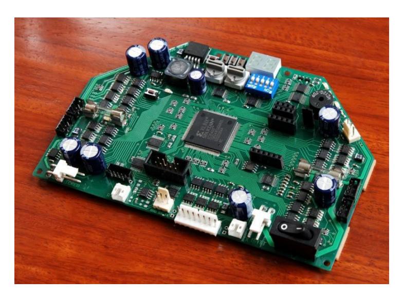
The main board consists of a Xilinx Spartan-3 XC3S400 FPGA, motor driver, user interface, some add-on modules and debugging port. The microprocessor core and interfacing logic for external peripherals are implemented using FPGA in order to handle the low-level control of the brushless motor such as velocity and position control. The main electronics board receives commands from the main software on a computer. The board integrates the processing components together with the power components to keep the board compact and minimize wiring. With limited space, almost components are in small SMD packages. However, these components still large enough for hand soldering with conventional tools. Figure 1 show the main electronics board of the robot.
2.2 Motors
There are two types of motor in the robot, the driving motor and the dribbling motor, both are brushless motor. Each driving motor is a 30 watts Maxon EC45 flat motor with a custom back-extended shaft for attaching encoder wheel. The motor itself can produce a feedback signal from hall sensors for measuring wheel velocity. However, this multi-pole motor sends only roughly 48 pulses per revolution; therefore, this motor is equipped with an US Digital E4P encoder which have higher resolution of 1440 pulses per revolution. The dribbling motor is a high speed 15 watts Maxon EC16 motor. Despite a very low resolution of 6 pulses per revolution signal from hall sensors, the implementation of the PI controller is possible when running this motor at high speeds. The maximum speed of the dribbling bar is about 13000 rpm.
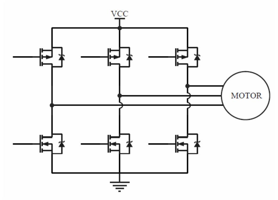
The motor driver is a three phase inverter circuit using complementary N and P channel power MOSFET in each phase. This configuration doesn"t require bootstrap driver as in N-channel-only configuration. These MOSFETs are driven by MOSFET driver ICs to minimize switching loss. The motor commutation and PWM generation are described in the firmware section. Figure 2 shows the three-phase brushless motor driver circuit.
2.2 Wheels
Robot has 4 omni-directional wheels driven by 30 W Maxon flat brushless motors.Each motor has been attached by a 360 CPR optical encoder in order to measure motor speed.
2.3 Dribbler
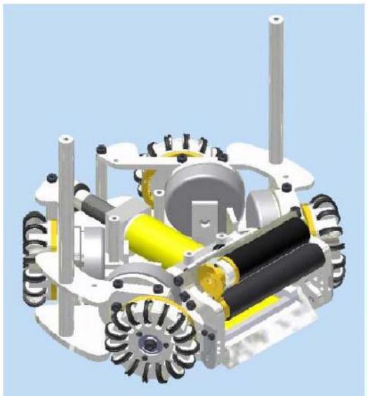
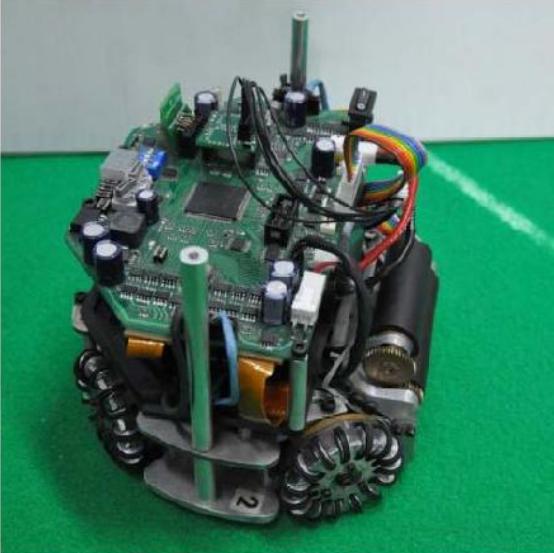
The Dribbler, which use for drib ball, consist of round bar cover by silicone tube and connect with high speed motor which can run up to 13000 r/m. It will cover 20% of ball diameter when the ball. Figure 3. show 3d robot model and real robot.
2.4 Kicker
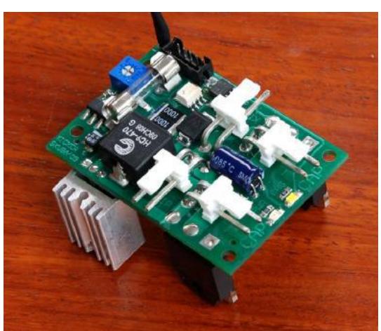
The kicker use solenoid to kick the ball with highest speed is 14 m/s. The chip-kicker is a flat solenoid attached with a 45 degree hinged wedge on the bottom of the robot which can kick the ball up to 7.5 m. Both kickers are driven by two 2700μF capacitors. Each kicking device is controlled by separated board below the middle plate. This board consists of power switching devices: MOSFET and IGBT which are controlled from the main board. The kicker board is depicted in Figure 4.
3 Software
(This is the Software section header)
3.1 Software Architecture
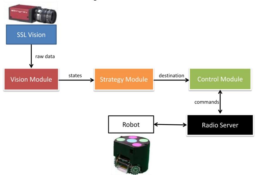
The software based on the strategy structure of Cornell Big Red 2002"s software. This software has been being continuously developed since Robocup 2006. The software consists of many modules and each module has own task to manage. Software Architecture is shown in Figure 5.
3.2 SSL Vision
The use of shared vision system named SSL-Vision is required by the competition rule. This new vision software can be integrated into the system by simply replacing our Vision Server software. With some code changes in the vision protocol, the existing software works with the shared vision system successfully.
3.3 Vision Module
This module was liable for taking the vision data, extracting velocity information from it, and predicting the location of the robots and the ball in the future frame. Our total system latency, measuring from the period between command velocity and raw velocity, is approximately 133 ms (8 frames). When our robot move at the fastest speed, that is up to about 3.5 m/s, the distance between real robot position and the robot position from vision data will grow up about 47 cm. In order to correct this error we have to estimate the positions and orientations of the robots.
3.4 Ball Prediction System
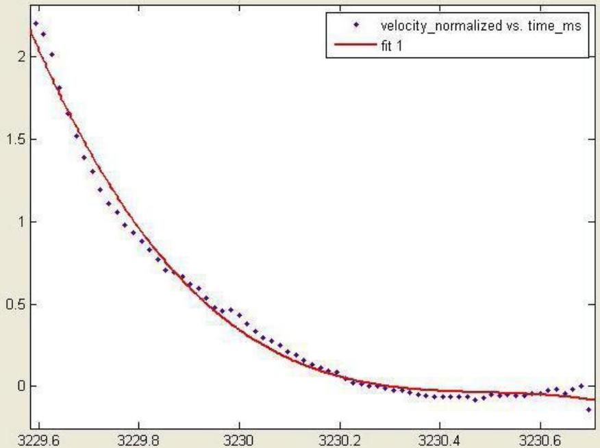
The estimated state from Kalman filter is not accurate enough to predict the real ball position and velocity because two main issues. One is ball model is not good enough and two is vision system which are lens curvature and an overlap area between two cameras. The precise model of the ball movement is described. There are two state of the motion, first is rolling and second is slipping [3]. But if the motion of the ball is directly implement, the extended Kalman filter is used. Moreover, all of the parameters in the equation must be found in different field. Therefore, in order to make the predictor easier, the experimental approach is selected. The velocity of the ball, which is controlled by robot kicking system, in every frames are collected and fitted to a single equation which is the cubic polynomial expression shown in Fig. 6. Peak of ball velocity is considered and used as a main component in order to fit the cubic curve. The cubic polynomial is now use as the new pre-predicting function and used in every module in our software.
3.5 Strategy Module
Duty of Strategy Module is plan a strategy and commands for robots. Our strategy module design is based on Cornell Big Red 2002.
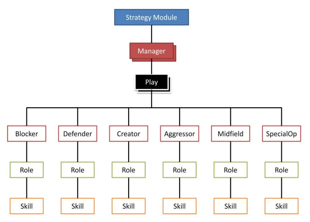
After receiving data from referee box signal, Manager will select the group of play that suitable for that moment.
Strategy module consists of several "Plays" which represent the play formation of team. Compare with human soccer, Play is like the formation such as 4-4-2 , 4-5-1, 4-3-3 etc. Play also includes the formation such as free kick, throw in, corner kick etc.
When Play is executed it calls "Role" for current robots. The Role will call the "Skill" which implement individual behaviors such as go to point, passing, shooting etc. There is an object that implement group of robots behaviors that call "Action". Action controls a group of robot to do "group behavior". We use Action to implement frequently use behaviors such as Wall, Defender, Stop etc. to reduce programmer work. Actions give programmer more comfortable to implement 'Play'. For example, If you want to implement Play that use 2 attackers you don"t have to handle defenders because it already implement in "Defender Action". Just call it and control only attackers.
3.5.1 Role Definition
There are five robot position on the field Blocker, Defender, Aggressor, Creator, and SpecialOP. Each position has own definition and duty.
Blocker( or Goalkeeper ), main role of blocker is to protect goal from opponent"s shooting. Blocker will attempt to block the ball that opponent shoot and clear ball inside the goalie box.
Defender is the role that cooperates with Blocker to defense the goal. It keeps position near our goalie box. Attempts to reduce the opponent"s shoot angle and clear ball when it is near our defense area before opponents are able to shoot.
The Aggressor is the most active robot on the field. It"s always looking for the ball. See a robot go up to an opponent who has the ball, either to screen him from our goal or steal the ball away and try to score whenever it possible.
Creator is a robot that supports the Aggressor. Main role of Creator is to create opportunities in Attack. Creator try to move into position that has high chance to score if Aggressor passing to and rebound the shooting that was blocked by opponents.
SpecialOP, the role off SpecialOP is not fixed depends on Play. When Play need more defender The SpecialOp acts as an auxiliary defender. When available, the SpecialOp may screen auxiliary opponents who are coming down the field from getting near the ball. He may also help block passes or shots on goal. Usually he roams slightly in front of the Defender. This role is called as SpecialOPDefender.
Second role of SpecialOP is SpecialOPAggressor. Duty of this position is assists the aggressor by running screens to help the aggressor dribble up the field, pick up the loosing ball, and also getting open for quick passes upfield.
The Last role of SpecialOp is SpecialOpCreator helps the creator to create opportunities by screening opponents. He also gets open for a pass under such scenarios.
In this year, the major rules are changed by add another robot to the field. So, we have to define position for the new robot. The new robot is defined as 'Midfield'.
Midfield keeps position behind the Aggressor and Creator in middle field. To support both Aggressor and Creator, It will grab the ball that loosing and either shooting or passing to upfield. If opponents get ball before and attempt to counter attack. It will slow down opponents by screen them and let Aggressor and Creator come back to steal ball back or do by itself.
The reason that we define this role to new robot is because we have seen problem in Robocup 2011 that we face more difficult to score because opponents put many robots in front of goalie box. When shooting was blocked, the ball was reflected back to defense area and Aggressor has to go to defense area and get ball back to attack again. This problem causes the game discontinuous and slow. Moreover, there is some scenario that opponent robot get the ball before us and don"t have any robot challenge them because Aggressor and Creator are on Kill Zone and Death Zone and Defender keep position in front of goalie box. Thus, opponent robot can shoot easily.
Therefore, we think it should be robot that holds position in middle field to control game and support both Attackers and Defenders.
3.5.2 Automatic Strategy Planning
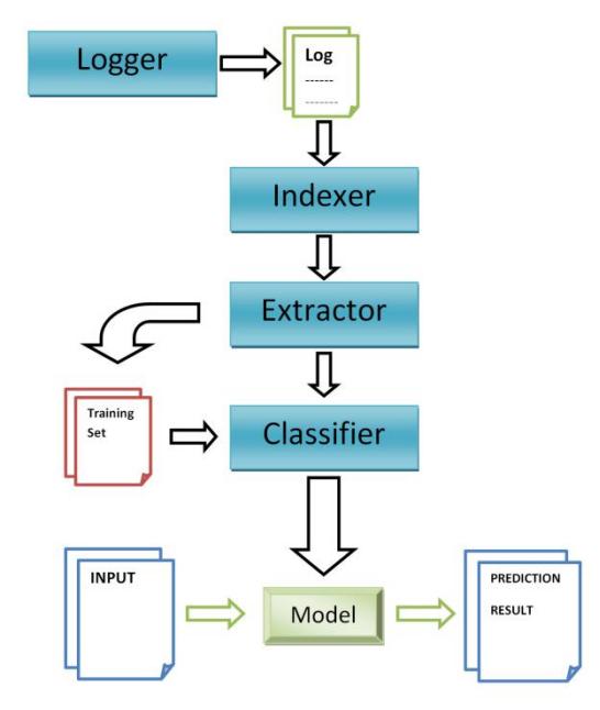
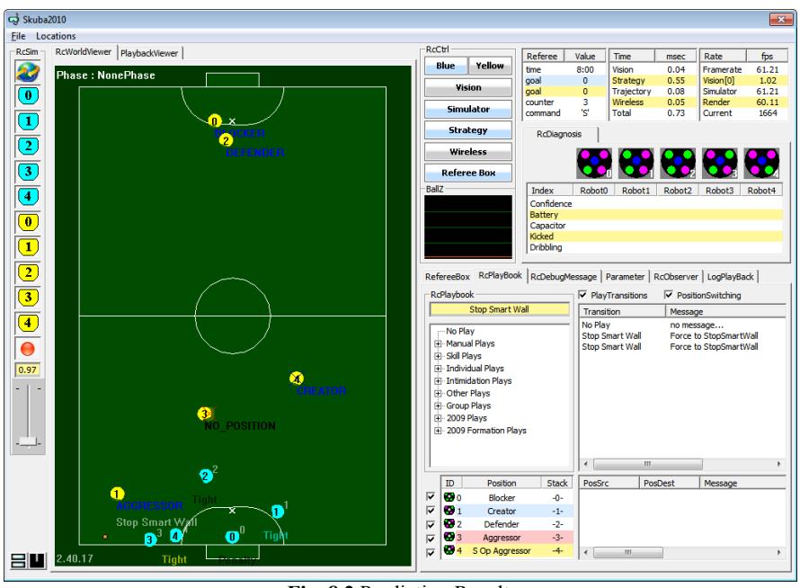
We use log data from real game and simulator and use those data to train the AI for predict position of opponent robots. We use data from log cooperate with the "Data Mining" technique with "Weka" which is a popular data mining software to specify the opponent robots position. Then, predict it behavior such as passing, shooting etc. So, AI is able to automatically choose Play that suitable for that moment based on opponent behavior. Figure 8 show system of Automatic Strategy Panning.
3.6 Control Module
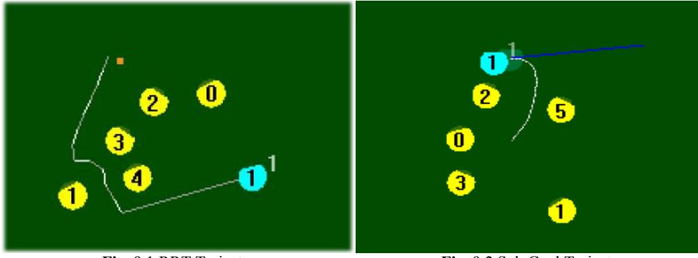
ControlModule receives predicted vision from VisionModule and destinations from StrategyModule and makes robots go to those destinations. So, the essential component of ControlModule is a path planning algorithm. Since the World Robocup 2008 at Suzhou, we have made use of the "Real-Time Randomized (RRT) Path Planning for Robot Navigation" for default path planning algorithm and use of the "Sub Goal Path Planning" for fast move planning algorithm[5].
After the ControlModule get command to navigate robot from the start point to the end point, the ControlModule will find the path (RRT or Sub Goal) by using start position, end position, initial velocity along x and y axis and direction of starting point and ending point. The result path will be calculated the usage time in order to use this information generates the velocity command which will be sent to the robot. Sometime the velocity is limited by the maximum acceleration of the robot. The velocity command is generated separately to the every point along the trajectory according to the frame rate. Each frame has its own velocity command. If there are any obstacles block the robot path, the path planning will be spited to small straight line to avoid collision. Figure 9 shows trajectory of RRT and Sub Goal.
3.7 Pass-Shoot Strategy
Skuba have several attacking approach to score opponent. The one approach that we regular use to be Pass-Shoot strategy. Pass-Shoot strategy is a popular attacking strategy for robot soccer (same as human soccer). It uses two robots pass and shoot without touch. This tactic works because, in general, defender will stand in position which relate to the ball. When ball is passed from robot to another the defender's position will be change according to the ball position. If a robot passes and shoots a ball with high speed, it might cause a defender can't change position fast enough and you will score. Figure 10 show visual image of this strategy.
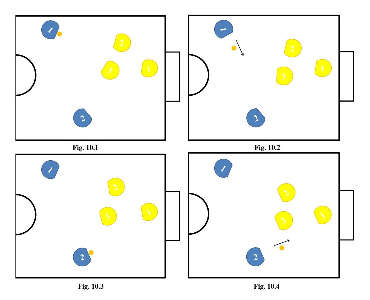
The key of this strategy is a position that suitable for shooting with high chance to score. Moreover, It is a position that attacker is able to pass to receiver without intercepted by opponents. To find this position, we have to consider many variables as following:
- P is a point that robot receive the ball and immediately shoot.
- X is a passing angle which got by create a triangle from ball position to point P without robot.
- Y is shooting angle construct by draw a triangle from point P to a goal area which doesn't have robot.
- D is a distance from ball to point P.
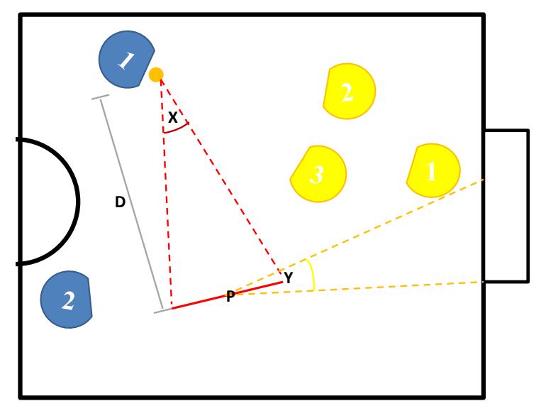
We have conditions for each variable, which we got from experiment in training and in real game, to evaluate a suitable point P. If you want more details, see the " CMDragons: Dynamic Passing and Strategy on a Champion Robot Soccer Team"[2] by James Bruce, Stefan Zickler, Mike Licitra, and Manuela Veloso.
However, there are some problems. Because of we have only 2 robots as attackers. So, when the ball belongs to us. Opponent can evaluate that if the robot, which has possession, passes the ball where is the destination since there is only one robot left.
We have added a new trick to this strategy to make it hard to predict and more complex, due to the new rule that increase number of robot from 5 to 6. So, if we assign the 6th robot as another attacker, the strategy would be more complex and difficult to evaluate. Because we have 3 attackers which means we have more choices for passing. So, It causes more difficult to predict the receiver for opponent.
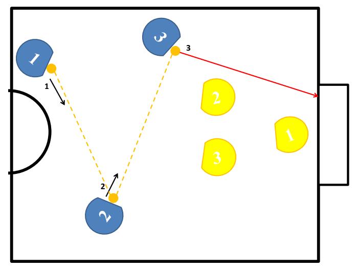
We add a new trick to a pass-shoot strategy. Since we have 3 attackers, so, we can perform 2 times passing. When we do 2 times passing, It is possible that defender will open more space. Figure 12 show visual image for a new trick of pass-shoot strategy.
3.7.1 Path Evaluate Algorithm
There are many possible solutions to find a path of passing. We design the path evaluate algorithm as show below.
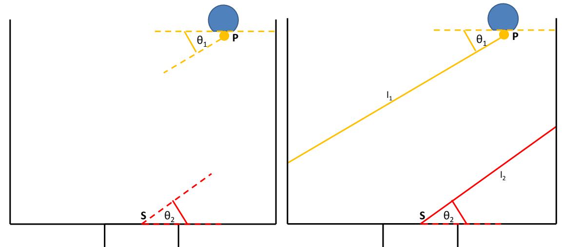
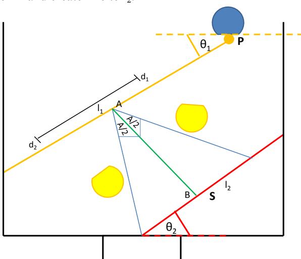
Let P is a ball position and S is a center of opponent goal. Construct θ1 and θ2as show in figure 13. Select n randomized values from θ1 and n values from θ2 in order to reduce the calculation time. For each θ1 and θ2, draw line l1 which has θ1angle which is referred from the base line. Create line l2 which has θ2angle from goal line by the same fashion as l1 as show Figure 14.
Let d1 is a minimum passing distance; d2 is a maximum passing distance as shown in Fig. 15(d1 and d2 depend on passing speed and robot structure). Use Local Search Algorithm to find point A between d1 and d2 that has maximum angle when project to l2 and doesn't have robot block the way as shown in Fig. 16.
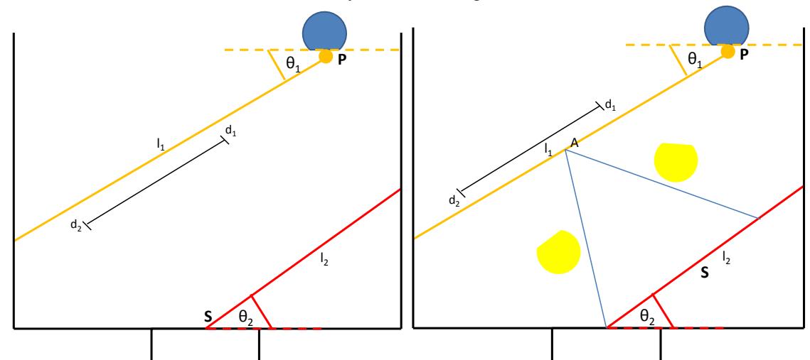
Bisection angle of A and create line to l2.
Finally, we will get a path of passing as show below.
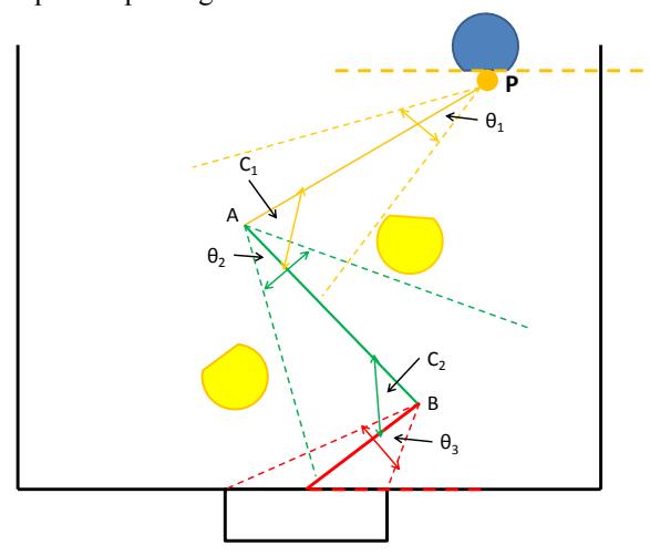
The evaluation estimates the time t as the pass length divided by the pass speed, plus the shoot length divided by the shooting speed. An angular preference k(c) , where k(c) increases linearly from 0 at c = 0 to 1 at c = 45◦. It stays at 1 until c = 90◦, where it decreases rapidly to 0. The evaluation function is then [k(c1) k(c2) min (θ1, θ2, θ3)/t]. After evaluate all θ1and θ2, the maximum value of evaluation is the best solution.
3.7.2 Decision Function
There is a problem of decision made by AI. Because it doesn't guarantee that double passing is better than the old one in every environment. So, it need to evaluate the best approach between 2 times passing or 1 time passing.
F = E(n) x min( D )
where
$$E(n) = \sum_{i=1}^{n} \frac{1}{n} k(\theta i)$$
n = number of passing
θi = angle of ith passing
D = { di ; where di is distance from opponent robot ith to passing path }
k(c) is calculated which increases linearly from 0 at c = 0 to 1 at c = 90◦.
It stays at 1 until c = 90◦, where it decreases rapidly to 0.
4. Conclusion
In this year, we mainly focus on developing strategy module which relate to AI system due to we already have stable robots. Our new trick in pass-shoot strategy which we add in this year still need more experiment and we try to do it in Robocup JapanOpen2012. This new tactics will make attacking more complex and hard to predict for opponents. If the result is coming out good enough, it possible to see a beautiful and complex passing game in robot soccer like in human soccer. Table 1 shows all competition result of Skuba since year 2005.
Table 1. Competition Result of Skuba
| Competition | Result |
|---|---|
| Robocup Thailand Championship 2005 | 3 rd place |
| Robocup Thailand Championship 2006 | Quarter Final |
| Robocup 2006 | Round Robin |
| Robocup Thailand Championship 2007 | 3 rd place |
| Robocup 2008 | 3 rd place |
| Robocup 2009 | 1 st place |
| Robocup China Open 2010 | 1 st place |
| Robocup 2010 | 1 st place |
| Robocup Iran Open 2011 | 1 st place |
| Robocup 2011 | 1 st place |
5. Reference
(This is the References section header)
References
- Krit Chaiso, Kanjanapan Sukvichai : Skuba Extended Team Description. In Proceeding of Robocup 2011.
- James Bruce, Stefan Zickler, Mike Licitra, and Manuela Veloso: CMDragons: Dynamic Passing and Strategy on a Champion Robot Soccer Team.
- Raul Rojas, Mark Simon : Like a rolling ball , FU-Fighters , The Book Robot Playing Soccer.
- Piyamate Wasuntapichaikul, Jirat Srisabye, Chanon Onman, Supparat Damyot, Chinatun Areeprasert and Kanjanapan Sukvichai: Skuba 2010 Extended Team Description.
- Bruce, J., Veloso, M.: Real-time randomized path planning for robot navi Proceedings of the IEEE Conference on Intelligent Robots and Systems. (2002)