2012 Team Description Paper: UBC Thunderbots
Andrea Palmer, Jordan Balanko, Christopher Head, Jonathan Fraser, Sandy Lum, Matthew Parizeau, Henry Poon, Terence Lin, Christian Villar, Komancy Yu, Brian Wang, Ho Ming Tay, Bonnie Lee, Shiyu Liang, Matthew Lai, Rafael Quintero, Mireille Ghoussoub, Alice Lam, Aaron Liu, Sarah Holdjik, Charlie Liu, Steve Huynh, Amy Leson
The University of British Columbia
Abstract This paper details the 2012 design of UBC's Small Size League team, to be entered at RoboCup 2012 in Mexico City, Mexico. The main focus of this year was to address the mechanical and electrical weaknesses in the robot from last year, and to build on the existing artificial intelligence of the robot to implement new behaviours and features.
INTRODUCTION
UBC Thunderbots is an interdisciplinary team of undergraduate students at the University of British Columbia. Established in 2006, it pursued its first competitive initiative within the Small Size League at RoboCup 2009. The team also competed in RoboCup 2010 and 2011 and is currently seeking qualification for RoboCup 2012. Over the years, it has made significant developments of its team of autonomous soccer playing robots. This paper will outline the progress in implementation of the current model of robots, focusing on the mechanical, electrical and software components with particular emphasis on the dribbler system, the electrical communication and the artificial intelligence (AI) plays.
MECHANICAL DESIGN
The maximum dimensions for this year's robot can be found below in Table 1.
Maximum Robot Dimensions
| 148 mm | MAXIMUM HEIGHT |
|---|---|
| 178 mm | MAXIMUM DIAMETER |
| 18.1% | MAXIMUM BALL COVERAGE |
2.1 Dribbler System
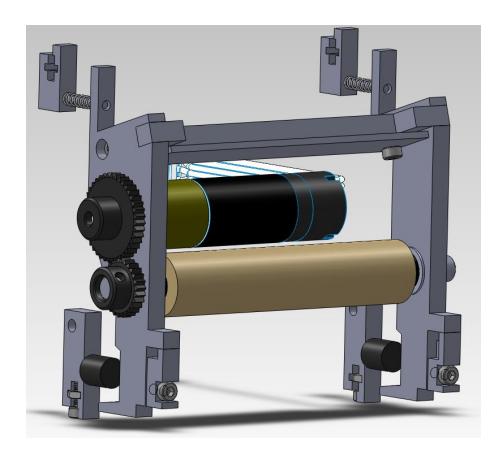
The 2012 dribbler design aims to optimize its performance in ball reception and control through three main features: an improved energy dissipation mechanism and two main ball position sensors. In past years, we have often discovered that it is very difficult to reliably dribble the ball; the dribbler will often jam and stop rotating, bounce the ball instead of holding it smoothly against the roller, or lose control of the ball during robot movement, making the energy dissipation and dampening a significant part of the design of this year's dribbler.
To control the ball's impact on the dribbler, the mass of the dribbler has been adjusted so that an incoming ball at 8 m/s can be reduced to 0 m/s after impact. This is achieved through careful analysis of the momentum transfer and energy dissipation characteristics.
Upon the dribbler's impact with the ball, some of the ball's kinetic energy will be dissipated and the rest will be transferred to the dribbler system. The system (rollers, side plates, motor, etc.) will then slide along the base plate. This motion will cause compression in the two compression springs. The system reaches the end of its linear range when it impacts the shock absorber (or bumper), which will dissipate a significant portion of the system's kinetic energy. The compression of the springs allow the system to be pushed back to its equilibrium position.
Sensors The break-beam sensor is able to detect whether the robot has possession of the ball. The addition of this sensor was motivated by the need for a fast-feedback system that could indicate when the robot is properly positioned to kick the ball, which can enable an on-board auto kick trigger. This year's design compensates for a previous failure mode in which the the transmitter and receiver became misaligned. It features a more robust mounting system: a surface mounted laser diode and receiver pair on printed circuit boards, mounted to the dribblers milled aluminum side panels with screws, thus giving precise angular alignment.
The lateral position sensor performs the function of detecting where the ball is along the length of the dribbler roller's axis of rotation while the robot has possession of the ball. This feature did not exist in the team's previous design and its addition was motivated by the need for knowing how accurate a kick could be or where the ball would go after a kick depending on the position of the ball.
2.2 Kicker
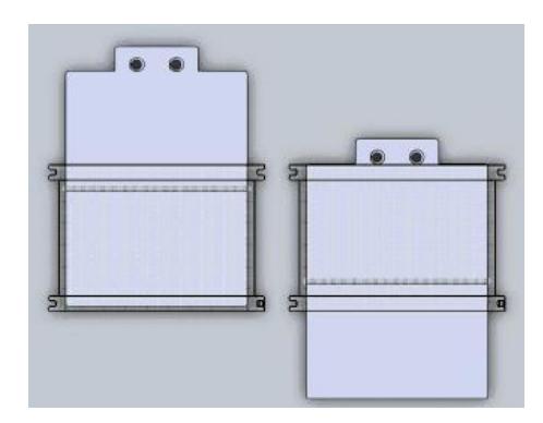
The function of the kicker is to allow the robot to shoot the ball in a plane parallel to the plane of the field. The major change in this years robot is the implementation of the new custom-made flat solenoids, as opposed to the use of off-the-shelf cylindrical solenoids (see Section 2.5 for more detail about the solenoid design). The transition from a cylindrical-shaped solenoid to a flat design simplifies the implementation of the kicker into the robot, eliminating issues with mounting as well as plunger rotations. The kicker uses a push-type solenoid to impart an impulse on the ball. Figure 2 below shows the position of the plunger in its initial standby condition (left), and the position of the extended plunger at the end of the solenoid stroke (right).
The plunger is fabricated by welding two different metals together. The back portion of the plunger which moves through the solenoid is mild steel, selected for its high magnetic permeability to maximize the force imparted by the solenoid, and the front piece which makes contact with the ball is stainless steel, selected for its high strength, flexural rigidity, and non-magnetic property. Since the stainless steel is non-magnetic, it essentially extends the reach of the plunger closer to the ball with negligible effects on the magnetic interaction between the solenoid and mild steel. The length of the plunger is thus designed so that the plunger makes contact with the ball when the force generated by the solenoid is at a maximum, i.e. when the mild steel is centered in the plunger. Testing has shown that the current kicker system is able to kick the ball at a speed of 7.33 m/s.
2.3 Chipper
This years robot includes the addition of a ball chipping system. The main function of the chipper is to project the ball above the plane of the field. A sub-function of the chipper is to protect the ball from being pulled under the robot by the dribbler it prevents the robot from being lifted up by the reactionary force.
The system consists of a 120 mm x 60 mm plate that rotates about a pivot placed 42mm away from the end that contacts the ball. The chipper plate is composed of stainless steel slightly bent around the edges to increase the plates moment of inertia and thus the bending stiffness. In its initial standby condition, the chipper is angled 45 degrees from horizontal; at the end of its chipping stroke, the chipper has swung 20 degrees to be angled 25 degrees from horizontal. The chipper uses a custom-designed pull-type solenoid. The solenoid is mounted at 25 degrees from vertical so that it is perpendicular to the chipper plate at the end of the stroke. The chipper should therefore accelerate throughout the stroke, carrying the ball further before releasing it at the highest possible angle.
2.4 Drivetrain
The drive train system moves the robot both in translation and rotation motions. The system consists of: Motor mount, Motor, Gears, Encoder, Shaft, and Wheel. The following section will describe the premise for the drivetrain design.
Motor Mount The motor mount consists of a piece made from a metal sheet that connects all the components in the drive train, it acts as the column vertebrae of the system. It has holes that support the motor, shaft, and gears. It is also connected to the base plate of the robot to connect the system to the robot itself. It determines the angle that all the center lines of the wheels make with respect to each other. The motor mounts are now common to both the front and back wheels. This aids in faster and cheaper manufacturing, as well as the ease of installation of the drive train into the robot.
The motor converts the electrical power given by the circuit board into mechanical power to rotate the wheels. The motor used is a Maxon EC Flat 45 with integrated electronics. It has a speed range of 200 - 7000 rpm depending on the electrical input and variation. The motor is the same as our 2011 model as it gives us enough torque and acceleration for the robot's movement.
Gears The gears in the drive train transmit the rotational motion from the motor to the wheels. The pinion, or driving gear, is connected to the motor shaft and to a larger gear that is on the same axis as the wheel. The ratio between these gears is 5:4; that is, for every 5 rotations of the motor, the wheel rotates 4 times. This ratio differs from our ratio of 7:2 from last year. The significant reasons for this change include moving the smaller gear closer to the wheel to save space; moving the large gear further from the wheel, dribbler and baseplate; to allow the motors to be lowered (vertically) to lower the center of gravity of the robot; and to increase the maximum possible speed of the robot.
2.5 Solenoid
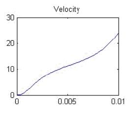
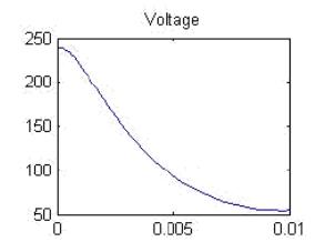
The solenoid design this year is done with two main objectives. First, the achievable maximum velocity of the ball must be the 8 m/s, as set by the committee. Second, the voltage drop across the discharging capacitor should be as low as possible to maximize the efficiency of the solenoid. A MATLAB model of a solenoid was used to simulate graphs of the velocity of the ball against time and voltage drop across the capacitor against time. The height of the solenoid is reduced to allow for space for a chipper solenoid, a new design incorporated into the robot. Mechanically, the solenoid has a plunger made of mild steel and a housing made of polycarbonate. With regards to the mechanical constraints, the solenoid design is built based on the model shown in Fig 3.
ELECTRONICS
Placeholder for section content.
3.1 Communications
Before Istanbul 2011, it was determined that running bidirectional communication using a single set of XBees on a single radio channel was causing significant performance problems. When all nodes were transmitting arbitrarily, there were collisions and delivery failures. When only the host transmitted and a poll code in outbound packets was included to indicate which robot should send data inbound, it was found that round trip times were high enough to cause timeouts. As a results, timeouts had to be set to very high values leading to jitter in delivery rates in outbound data if the poll code or inbound reply were dropped. For the 2011 competition, this problem was resolved by installing two XBees on each robot and on the host and using separate channels for outbound and inbound communications. This resolved the dropped deliveries and data collisions, but lead to slow communication and large latencies due to buffering.
This year's robots use the Microchip MRF24J40 communication chip, which uses the same 802.15.4 standard as the XBees. These chips offer a number of advantages over the XBees. First, they offer greater control over the spectrum: while XBees can only operate in ad-hoc or non–beaconed coordinator mode, the MRF24J40 is also capable of operating in beaconed coordinator mode. This enables the use of the slotted carrier sense multiple access/collision avoidance algorithm, which yields a lower probability of collisions overall.
It also enables the use of guaranteed timeslots managed by the network coordinator, which can be used to segregate high-bandwidth traffic away from other traffic to reduce collision rates further. A second advantage of the MRF24J40 is that it is easier to program: while XBees communicate over asynchronous serial using a packetization protocol that requires synchronization of start bytes, unescaping of data to avoid synchronization ambiguity, and an interrupt handler to achieve adequate transfer rates, the MRF24J40 acts as an SPI slave. This provides a higher bus bandwidth (10 Mb/s instead of 250 kb/s) while also completely eliminating the need for special start-of-packet indicators and escaping, instead using the SPI chip select line to maintain message boundaries.
A third advantage is that the MRF24J40 offers a proprietary mode of operation which is identical in structure to standard 802.15.4 but with the symbol rate increased to 625 kb/s, achieving a 2.5 times increase in over-the-air bandwidth.
Finally, the MRF24J40MA, MRF24J40MB, and MRF24J40MC, professionally designed circuit boards packaging the MRF24J40 MAC/PHY chip along with the necessary amplifiers and RF switches to achieve a complete radio solution, provide a range of transmit power levels and receive sensitivity ratings similar to those available on the XBee and XBee Pro but at significantly cheaper prices.
3.2 Lateral Ball Position Sensor
As described in Section 2.1, this year's robots will implement a lateral ball position sensor. The robots already possess horizontally mounted lasers below their dribbler rollers which detect the presence of the ball when they are interrupted. However, these lasers cannot detect the position of the ball horizontally along the length of the dribbler roller. The lateral position sensor comprises a set of four illuminating LEDs with adjacent light sensors. By measuring the relative amount of light reaching each sensor from each LED, the position of the (reflective) ball can be determined. This sensor was initially intended to help our robots centre the ball on their dribbler rollers for the multi-directional kicker [1], a task which is no longer necessary with our current kicker design. However, it can still provide highly accurate feedback about the exact position of the ball, which is useful information for the AI when choosing a robot orientation in preparation for kicking or when attempting to carry the ball without dropping it.
3.3 Motor Control
Our brushless motor driving and kicking subsystems will continue to implement an FPGA to read the motors' Hall effect sensors and commutate and modulate power to the motors. However, there have been reliability problems leading to failure of the MOS-FETs and MOSFET drivers on the motors' phase lines, often during system startup. To solve this there is a use of a different model of the MOSFET driver, which will alter the polarities of control signals to be in safer states during boot.
3.4 Kicker and Chipper Boards
The kicking subsystem will be adding a chipper, which was not present on past robots as it had not been mechanically designed. This will not influence the electrical design of the kicking subsystem, however, as the previously attempted multidirectional kicker mechanism already required two channels of solenoid energization control ([1]).
The charging circuit board has been redesigned to move the bulk capacitors directly onto the board in an attempt to eliminate wires running around the robot which can get caught in other hardware. The solenoids for both the kicker and chipper are also being redesigned, see Section 2.5, and in order to increase the efficiency of the kicking subsystem, reducing power usage and increasing achievable kick frequency.
SOFTWARE
Placeholder for section content.
4.1 Skills Tactics Plays
The main high-level decision making model used is the STP model, developed by CM-Dragons in 2003 [4].
The STP model is used to manage multiple robots in a challenging adversarial environment. In this environment, the decision making model handle short dynamic events, while simultaneously trying to achieve long-term objectives. STP is composed of Skills, for executions of low-level actions, such as a simple move or kick; Tactics, that determine the skills for use by the robots; and Plays, which assign roles for the robots to execute tactics [3]. The hierarchical architecture within the STP model allows for dynamic quick response and coordinated control. The team will be able to achieve long-term goals in a highly coordinated manner, and, similarly, react to dynamic events initiated by the enemy.
At the top of the robot control hierarchy, the STP model makes decisions as to where the robots are destined, and the lower-levels of the hierarchy handle the path that each of the robots should take to get to the determined destination. Figure 4 shows the cycle of the STP model.
Defense The centerpiece of the team's overall defensive strategy (incorporated in all defensive plays) employs two defenders to assist the goalie with defending. The main goal of the the defensive strategy is to prevent the ball from reaching the teams goal, with secondary emphasis placed on defending against other threats, such as an enemy player that does not posses the ball but is in position for passing and making a shot at the defending teams goal. The goalie and defenders are positioned in a way such that together, they will always block all the possible linear paths the ball can take to reach the defended goal. All paths are bounded by two line segments that share a common point (the ball) and connect the two goal posts. In addition to this, the other players of the team will also try to actively defend by attempting to take the control of the ball from the attacking team.
Offense A new offensive strategy is being developed to take advantage of the newly added sixth player. This strategy will encompass three stages. The first stage is to utilize three robots, while the rest play defense. The offensive robots will be optimized for the ball possession sub-task, that is to keep the ball within the teams possession as long as possible through passes and positioning. The second stage is to position the offenders tasked with keeping the ball in possession in favourable shooting positions against the enemys goal, while not compromising the ball possession time. The last stage consists of making shots against the enemy goal with the group of assigned offenders. Given that a well defended enemy will to block and steal the ball, implementing a sound and effective offensive strategy is significantly harder and more complex than its defensive counterpart.
The incorporation of a sixth player onto the team, among other rule changes, will be easily incorporated into the STP model due to the extend-able characteristics of the AI architecture. However, given that the nature of the game is going to be predicted drastically different, new STP components well have to be invented, while previous components will also have be revamped to take into account of scenarios that were impossible before.
4.2 Controller
The control system for the robots consists of 2 major components, the first being the AI level controller and the second being the firmware controller inside the robots themselves.
AI Controller The AI level controller is responsible for positional control and exists directly below the navigation layer in the AI architecture. These controllers receive a path consisting of points and deadlines which they use to compute robot velocities. This level is relatively simplistic in in its implementation and is only complicated by the multi-dimentionality of the problem.
A delta is computed between the current and desired position of the robot, this delta is of all three degrees of freedom (X,Y and Theta). The Delta is transformed into a velocity by division with the deadline (if the deadline is shorter than 1 AI tick the deadline is extended to that). These three velocities are then transformed into the wheel velocity space by multiplication with the coupling matrix. If the difference of any component between this vector and the previous velocity exceeds the maximum acceleration, the entire vector is scaled such that the acceleration is maximal on one component. This process ensures linear ramp-up of all wheel velocities. These computed wheel velocities are then transmitted wirelessly to the robots in the fields to be later processed by the firmware level controller.
Firmware Controller The firmware level controller is responsible to quickly and efficiently accelerating the robot to the desired velocity set point, which it receives via radio link. Each wheel on the robot is independently controlled by a fairly basic PI controller. This controller is tightly tuned to a robot which is on the ground such that the robot inertia is accounted for. Data to compute the tuning comes from M-sequence excitation of the robot motors, with responses subsequently read by precision encoders attached to the motor shafts. The output of this controller is then acceleration limited so as to minimize wheel slip and accomplish a linear (de)acceleration. In order to prevent integrator wind up due to the acceleration cap, and the voltage of the robot, an anti-windup compensator is present. This consists of a linear model of the robot, which receives as input the difference between the controller output and the actual value sent to the motors. The output of this model is then subtracted from the error signal that would normally be used as the input to the PI controller.
4.3 Predictor
This year, in order to shorten the response delay when passing between friendly robots, the manoeuvring of receiving a moving ball has been architecturally moved to the navigator layer. The navigator layer has the advantage of direct communication to the lowest level of AI and global knowledge of the every robots movement path. The algorithm evaluates, at many sample points, the time it takes the ball to roll to the position and the amount of time the robot needs to get there. The algorithm then commands the robot to move to the closest position that satisfies the above requirement. In order to assist this algorithm, architectural support is added for evaluating timestamp based on a robots and the balls future position. This algorithm works reasonably well, but it is constrained by our cameras ability to track a fast moving ball. A moderate kicking speed ensures optimal performance.
Acknowledgements
We'd like to thank the Faculty of Applied Science; the departments of Mechanical Engineering, Mining Engineering, Electrical Engineering, Engineering Physics, and Computer Science; and the University of British Columbia for their continued support. We'd also like to thank all our sponsors for their generous contributions to undergraduate student learning and research.
References
- Palmer, A., Jiwa, A., Huynh, S., Head, C., Fraser, J., Leson, A., Knoll, B., Suyadi, S. 2011 Team Description Paper: UBC Thunderbots, 2011.
- Jiwa, A., Knoll, B., Head, C., Hu, H., Fraser, J., Serion, J., Baillie, K., Lam, LT. 2010 Team Description Paper: UBC Thunderbots, 2010.
- Browning, B., Bruce, J., Bowling, M., Veloso, M. STP: Skills, tactics and plays for multirobot control in adversarial environments, 2004.
- Browning, B., Bruce, J., Bowling, M., Veloso, M. CMDragons03 Team Description Paper, 2003.