CYRUS 2013 Team Description
Javad Amiryan, Sina Raeessi, Mohammad Moallemi, Mostafa Nazari, Abolfazl JafarzadehPour, Sina Mohammadzadeh, Amin Nikoukar, Mahdi Aali, Nariman Eskandari
Department of Electrical and Computer Engineering of Shahid Beheshti University; Department of and Architecture and Urban Planning of Shahid Beheshti University; Department of Computer Engineering of Sharif University of Technology
Abstract In this paper some developments and programs of Cyrus robotic team for participation in Robocup 2013 competitions will be mentioned. New Mechanical designs have provided more speed and accuracy for robots while electrical boards are redesigned to obtain more reliability. On the Other hand software system has been fully reconstructed and our last Java-based code has been completely substituted for a new Qt-based one. Moreover a robotic team manager application has been designed and developed for Android 4 which can be run on tablet computers and bring some useful tools for team coaches.
1 Introduction
We`ve gained many experiences by participating in 4 national and international tournaments and each year many related technologies have been imported to the team. In the last competition (Iran-Open 2012) our robots succeed to score goals for the first time [1]. This year as previous years, some changes are applied in both hardware and software systems. The mechanical parts are redesigned in order to achieve more accurate robots while some changes to electrical boards have been done to get more reliability and performance. In the following section, the changes in mechanical system will be mentioned. Afterward new FPGA-based main board will be proposed. In section 4, new software architecture would be surveyed and also some explanations about our robotic team manager application will be presented.
2 Mechanical Design
In new mechanical design we`ve focused on some criterions which will be discussed here. Since we still use brushed DC motors which have lower speed and power rather than BLDC ones, we decided to change the angle between the robot axels i.e. we increased the angle between rear wheels to 104° to achieve more velocity in forward and backward directions which helps to reduce the travel time. Secondly, by testing the position of different objects in the robot a suitable centroid was obtained. Besides new omni-directional wheels are built with larger sub-wheels which make the robot movement more precise.
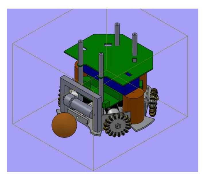
Each robot is 178mm in diameter and 138mm in height and at most covers 20% of the ball. A view of mechanical system is shown in Figure 1.
3 Electrical design
This year we focused on reliability of the boards and also the capability of precise control of driving motors. So a new FPGA-based main board is designed and implemented. Furthermore the kicker board which was one of our major troubles was redesigned and a more robust board one increases system provides the controlling signals to the driving system and kicker module and consists of two separate boards called the main board and the kicker board, respectively. The main reason for separating these parts is to reduce the effect of electrical noise caused by boosting and kicking functions of the kicker board on the other parts.
3.1 Main Board
The main board has the duty of receiving data via wireless module, analyzing it, and controlling the motors. It also sends commands to the kicker board as to determine the time and power of kicking. Our redesign of robots from 2009 to 2013 involves a completely new electrical subsystem. In 2010 we utilized ATMEGA16 MCU from AVR family microcontrollers. In 2011 we replaced our main microcontroller with ARM7 family - AT91SMA7X - and then in 2012 and 2013 Iran Open competition we designed our main boards based on ARM LP1768 which provides many better features. 100MHz clock speed in comparison to our last 50MHz clock speed and a cortex-M3 arm processor provides faster PI calculations for the controller division. In this case one of the board's advantages is the ability of easy programming which can be done by an onboard USB 2.0 port. Moreover in new design of the main board we focused on the robots' human interaction. Our board is perfectly designed for a right handed person who is going to debug the robot, calibrate the sensors or any interact with the robot.
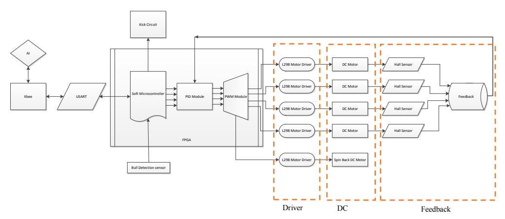
For Robocop 2013 we decide to utilize FPGA Spartan III family - Xilinx XC3S400 chip - as the only processor on the main board to generate all control signals for all parts such as wireless communication, kicking force, driving and so on. This chip is chosen because of its low power consumption, its high number of available pins and its huge logic gate numbers in comparison with other similar products. The Xilinx Spartan III, with its IP core provides significantly faster computation, when compared to the previous robot MCUs; besides Using FPGA, in addition of real-time benefits, would considerably reduce the number of components on the board and makes the debugging procedure much easier. Figure 2 represents the relation between FPGA and other units:
3.1.1 Motor Driver
The new driver system utilizes L298 motor driver which can support two DC motors, so only two drivers will be used in a main board which helps to have more congested boards and to ease board debugging.
3.2 Kicker Board
We have used advanced boost circuit topology with a current and voltage feedback on our robot's kicker board. The booster charges three paralleled 1600 μF-250 V capacitors up to 240 Volts using a voltage feedback to measure the capacitors' voltage and a current feedback to adjust the switching duty cycle. The change that has been made here is that we increased the PWM frequency in order to have a higher efficiency and reduce the loss of energy in inductors. We also used opto-couplers in order to isolate the control and power parts. In our new kicker generation we just applied some components for more safety. We also reduce our kicker board size up to 25% and make it more efficient and stable by preventing to be overheated.
4 Software System
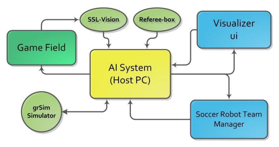
The software system is totally changed and new codes are rewritten in C++ language using Qt Framework while last software was developed with Java. The main idea for this transform is to increase software performance and still maintain the ability of running the code on any platform. The decision making system has been designed using STP Architecture. In Fig. 3 a view of software system is shown. The whole system is split to two separate parts for increasing modularity. The AI system would be run on the host computer and visualizer would be run on another one. Visualizer is a ui application which provides the same tools of Soccer Robot Team Manager App. This software is also developed using Qt Designer and connects to Host PC via TCP/IP protocol while receives data from it using UDP protocol.
4.1 Decision Maker
As mentioned before, this system is designed according to STP Architecture which is proposed by CMDragons [2]. In the head of this system there are two UDP sockets to make connection with vision and referee systems. After filtering the vision data, with Kalman filter, the World Model will be updated. As can be seen in Figure 3 in the test mode the vision data is captured from grSim [4]. This simulator is capable of generating vision data and sending it with the same format used by ssl-vision [3]. Moreover an optional additive Gaussian noise is considered which may bring the ability of testing the tracking system.
For task allocation, we have made a play library which is available in script file. The decision maker output determines a skill and a set of its parameters for each robot. The skills like go_to_point , receive_pass and so on might be the output of this system. The parameters are whether numerical or Boolean according to the skill. For implementation of path-planner module, the well-known RRT algorithm has been used.
After calculating the path and desired velocity for each robot an innovative module has the duty of generating motor velocities.
4.2 Calculating Motor Velocities
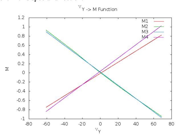
Experiences show that, the main issue in robot navigation is that the mechanical elements are not ideal i.e. the asymmetric forces between the robot wheels and ground result in imprecise movement of robot. For this problem we have proposed a new algorithm in which the mechanical system is assumed as a deterministic but predictable system. So a Takagi-Sugeno fuzzy method is used to estimate the effect of each motor on robot motion. For example in forward direction the plot is like Fig. 4. The different slopes for 4 lines show that the motors have not identical influence on robot movement in this special direction.
4.3 Soccer Robot Team Manager Application
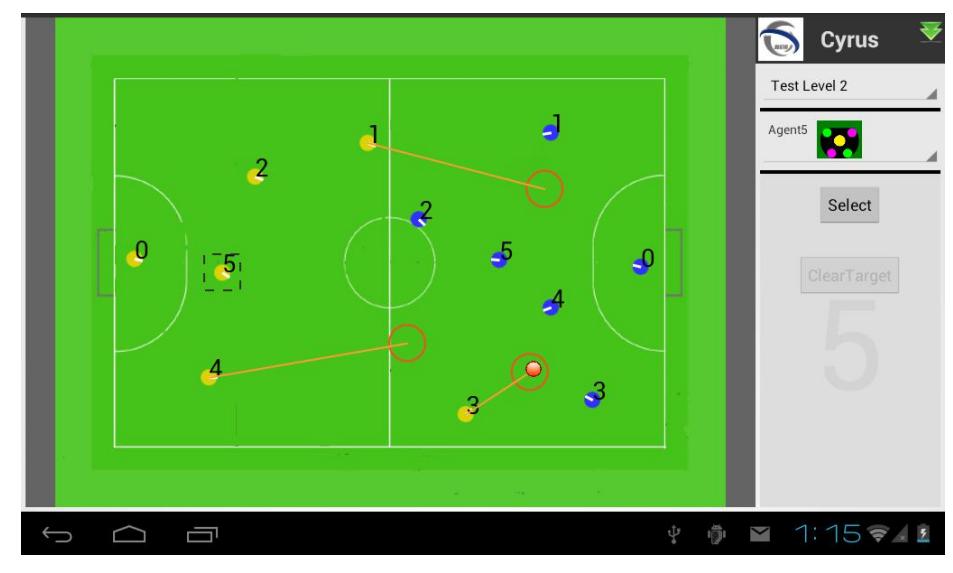
It is obvious that during a game some interaction between the decision maker computer and the team coach for debugging is inevitable. Although it is not allowed to team members to handle the computer when game is running but in time-outs and halftime it is allowed. Moreover sometimes it is desired for team members to see what decision the system is making e.g. what path a robot decided to go through. Therefor many teams use an individual Graphic Interface to perform such these works. This year we developed an android application which can help a team coach. Some of its major features are:
- Watch live game on a tablet computer showing score, time, …
- Detecting fouls in the game like double defender, ball-speed, …
- Monitoring the decision maker output
- Redefining team strategies
In Figure 5 a screenshot of this application is shown.
References
- Amiryan, J., Raeessi, S., Moallemi, M., Nazari, M., Zadeh, A. J., & Davoudi, M. CYRUS 2012 Team Description.
- Browning, B., Bruce, J., Bowling, M., & Veloso, M. (2005). STP: Skills, tactics, and plays for multi-robot control in adversarial environments. Proceedings of the Institution of Mechanical Engineers, Part I: Journal of Systems and Control Engineering, 219(1), 33-52.
- Zickler, S., Laue, T., Birbach, O., Wongphati, M., & Veloso, M. (2010). SSL-vision: The shared vision system for the RoboCup Small Size League. RoboCup 2009: Robot Soccer World Cup XIII, 425-436.
- Monajjemi, V., Koochakzadeh, A., & Ghidary, S. (2012). grSim–RoboCup Small Size Robot Soccer Simulator. RoboCup 2011: Robot Soccer World Cup XV, 450-460.