Eagle Knights 2013: Small Size League Team Description Paper
Marco Morales, Andre Possani, Alberto Candela Garza, Alan Córdova Posadas, Alejandro Escalante Arrieta, Juan Carlos González Sosa, Luis Eduardo Pérez Estrada, Jorge Pérez Rentería, Karen L. Poblete Rodríguez, Hipólito Ruiz Galeana, Javier Sagastuy Breña, Fabiola Terán, Jorge C. Urteaga Reyesvera, Miguel Angel Valenzuela Sánchez, Hector Vidrio
Robotics Laboratory, Department of Digital Systems College of Engineering Instituto Tecnológico Autónomo de México - ITAM, Mexico City, Mexico
http://robotica.itam.mx/ssl · http://youtu.be/DDUJYdTUnmA
Abstract In this paper we describe the architecture we have been using and improving since 2009 for our RoboCup Small Size League 2013 team. Since 2012 we have improved our hardware and software. In hardware, we compute in a different way the speeds of our motors, and we have a new PID robot controller. In software, we are developing new components for decision making.
1 Introduction
In this document we provide an overview of the software and hardware of the SSL Eagle Knights team. The Eagle Knights SSL team was founded in 2003 and participated officially for the first time in Robocup 2005. Our team was the first Latin American team consistently obtaining top results in all its regional RoboCup participation, 3rd and 2nd place in US Open 2003 and 2004, respectively, and 1st place in Latin American Open 2004 and 2005. We have also participated in the last eight RoboCup competitions: Osaka, Japan 2005; Bremen, Germany 2006; Atlanta, USA 2007; Suzhou, China 2008; Graz, Austria 2009 ; Singapore 2010; Istanbul, Turkey 2011 and Mexico City, Mexico 2012.
The official website of Eagle Knights: http://robotica.itam.mx/ssl Qualification video URL: http://youtu.be/DDUJYdTUnmA
2 Team Constitution
Our team is integrated by Faculty and undergraduate students from Instituto Tecnológico Autónomo de México (ITAM).
- Faculty Advisor. Prof. Marco Morales, PhD.
- Faculty Member. Prof. Andre Possani, PhD.
- Hardware Division. Alberto Candela Garza (ME&IE), Jesús Cozaín (CE), Alejandro Escalante Arrieta (CE&BAM), Jorge Pérez Rentería (CE), Javier Sagastuy Breña (CE&BAM), Jorge C. Urteaga Reyesvera (TE).
- Software Division. Alan Córdova Posadas (CE&TE), Luis Eduardo Pérez Estrada (CE), Karen L. Poblete Rodríguez (CE&TE) ,Hipólito Ruiz Galeana (CE),Miguel Angel Valenzuela Sánchez (CE&BAM).
– Administration and Public Relations. Sergio Francisco Góngora y Moreno(CE), Juan Carlos González Sosa (CE&BAdmin),Fabiola Terán (CE), Hector Vidrio (CE).
3 System Overview
RoboCup [1] is an international joint project to advance research on artificial intelligence and robotics through a grand challenge: design a robotics soccer team able to defeat the FIFA world champion by 2050. The Small Size League aims to this challenge by promoting research on multi-agent cooperation and control. Two teams of six mobile robots up to 18 cm in diameter play soccer on a 4.05 by 6.05 m carpeted soccer field. Aerial cameras send video signals to a shared vision system[2] that estimates the position of the robots and of the ball on the field. This information is then passed to an AI system that produces control commands that are sent to each of the robots through a wireless link. An external referee box indicates the state of the game to the central computer.
We currently have six robots that satisfy the constraints set in the SSL rules:
The height of each robot is 140 mm
The maximum diameter of its projection to the ground is 178 mm The maximum percentage of ball coverage is 19%.
Since last year we have replaced the design of the motherboard. In 2012 we migrated the system completely from Texas Instruments TMS 320LF2812 boards to the Arduino MEGA 2560 microcontroller, in order to take advantages of the facilities that they give us. Comparing to the TI boards, Arduino is a trend board so it is easier to look for information when problems appear.
Also, we are working on specific parts of our software, mainly in the interface between the expert system and the highest level of hardware. Due to the change of the microprocessor we made, the architecture of the software system needed to be adapted. We are still using the same system of intelligence based on the CLIPS language developed by NASA, for programming intelligence systems.
Finally, we are planning to make some changes in the planning and control layers of our systems, that is why we are developing a Rapidly Exploring Random Tree (RRT) that will substitute the sequence planning module we use, it is still on testing phase.
3.1 Interfaces to the league's software
– The Shared Vision System digitally processes two video signals from the cameras mounted on top of the field. It computes the position of the ball and robots including the orientation of our robots and the opponents. Resulting information is transmitted to the AI system[2].
The vision system should be robust enough to compensate for errors since the overall performance of the team depends on it. The main object features used by the vision system are the colors defined in the rules of the SSL [1]. The ball is a standard orange golf ball. Each robot has a 50-mm circular patch, this patch is blue in one team and yellow in the other team. The main tasks of the vision system are:
- Capture video in real time from cameras mounted on top of the field.
- Recognize the set of colors specified by the rules of the objects of interest on the field (robots and ball).
- Identify and compute the orientation and position of robots in the team.
- Compute the position of robots of the opposite team.
- Track the objects on the field and compute their moving vector.
- Transmit information to the AI system.
- Adapt to different lighting conditions (color calibration procedure).
In the past, when we used our own vision system, we implemented a number of algorithms to make our system more robust to different light conditions. These algorithms include the use of a neural network to classify camera image pixels to a discrete set of color classes that is robust under different light conditions[3].
– The referee box. This module controls the flow of the game, the robots are restricted to obey its commands. The Referee communicates the different states that could occur during the play, sending a set of predefined commands to the AI system through a serial link.
4 Software
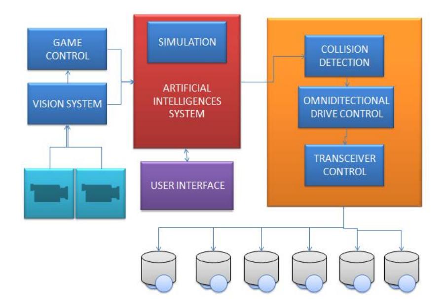
Our software comprises eight modules: Game Control, Vision System Communications, Artificial Intelligence, Simulation System, Robot Control, Collision Detection,Transceiver Communications and User Interface.
4.1 Game Control
This module receives referee commands through a serial interface and returns the state of the game.
4.2 Interface to the Shared Vision System
This module provides information about the state of the game scenario corresponding to the position, angles and motion vector of the robots and of the ball.
4.3 Artificial Intelligence System
It receives the information from the Vision System and makes strategic decisions. The actions of the team are based in a set of roles (such as goalkeeper, defense, and forward) that exhibit behaviors according to the current state of the game. These behaviors are encoded as rules of an expert system.
This module receives the position and orientation of all the objects in the field (robots and ball), game state, robots roles. It estimates the future position of each robot and the actions they should take. A Kalman Filter is used to estimate the heading of the ball. The strategies are programmed as rules on an expert system. Each rule encodes the actions that each robot can take in their assigned role: goalkeeper, defense, first forward, second forward, and third forward. For example, defense and goalkeeper rules are defined to block the ball from its moving path, while second forward rules are defined to try a pass to the first forward, and first forward rules are defined to shoot to the goal. The expert system organizes the rules into a tree and assigns a score to each node based on the antecedents of the rule and its priority.
The execution of the rule is a high level command for the robot to perform (e.g., passing, shooting, or blocking) that includes its linear and angular velocity and the use of the kicker and dribbler devices. These commands are converted into spline trajectories from which a speed vector is obtained for each robot to follow.
A geometrical exploring tree is used to avoid collision with robots of the opposite team [4]. Trajectories are computed based on splines. The AI system sends commands back to the robots through a wireless link.
4.4 User Interface
This module allows to visualize status information including: position, orientation and speed of the robot, game referee messages, control commands sent to the robots. It also allows to configure the AI system parameters.
4.5 Simulation
This module simulates robots and vision feedback in order to test system functions of the AI, collision detection and robot control modules without the actual vision system or robots being present. It allows to debug and test the artificial intelligence module. The field is visualized using a Python coded interface.
4.6 Transceiver Communications Module
This module builds the packets that must be sent. It send them using the transceiver. The information sent to each robot is the moving vectors and the angular speed of each one.
4.7 Motion Planning Module
This is a new module that we are developing in order to integrate trajectory computations with strategic decisions. This module will provide two main functions: role assignment, and collision evasion.
Role Assignment
We adapted motion planning techniques [6, 7] to perform dynamic role assignment in order to improve tactic decisions. This method receives the desired ball trajectory and state of the objects to produce trajectories for each robot. From the desired ball trajectory we compute a set of feasible plans that are ranked according to several criteria that include the relative position of the robots to the ball, their role, and their likelihood to help into moving the ball forward or to block it. The highest-ranked plan is chosen and executed. This method allows for planning from the perspective of the ball instead of the roles of the players. The goal is to better identify successful strategies. This method will be integrated with the expert system selection of actions through an arbitration process such that the motion plan is followed when it does not connect with the expert system.
Collision Evasion
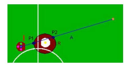
Allows our robots to avoid obstacles in real time (six robots in more than 60 fps). It receives the current and goal robot positions and plans evading paths through a geometrical exploring tree (GET), a variation of the rapidly exploring random trees [5]. A GET constructs a tree in each processing iteration rooted in the robot start position which is defined as an exploring node. Then, the tree grows as follows: a new node at a small predefined distance from the exploring node and on the segment that goes from the exploring node to the goal is generated. If there are no obstacles interfering with the new point then the tree is extended and the new point replaces the last exploring node. Collision is computed based on the geometry of the obstacles, in the case of a circular obstacle a possible intersection between the circle and the vector "A" is calculated like shown in Figure 3. In case of an intersection the distance between the obstacle and the new extension is validated to be smaller than a radio "R".
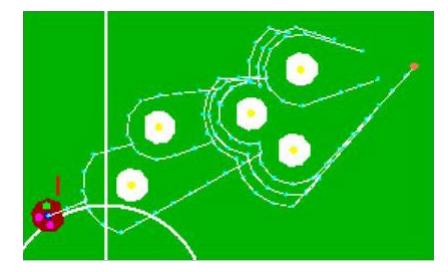
In the example shown in Figure 3 there are two intersections: "P1" and "P2". When the tree reaches the radio "R" , it will generate two possible routes at each side of the obstacle. These two points are now considered as exploring nodes. While the exploring node can not freely reach the goal then it continues surrounding the obstacle until there is not intersection or another obstacle. In this case a new obstacle is defined as the exploring node obstacle and the exploration continues surrounding the new obstacle as shown in figure 4.
5 Hardware
Last year (2012) our robots were significantly rebuilt. This year we have been fine-tuning those modifications, as well as adding new features.
Each robot has five Faulhaber 2224P0212 motors with gearheads 14:1 (four motors for the wheels and one for the dribbler) [6], a low resistance solenoid, a microcontroller, a Zigbee radio, a single printed circuit board and two Lithium Polymer batteries.
5.1 Microcontroller
Last year we replaced the Texas Instruments DSP for the Arduino MEGA 2560 microcontroller. We also had to make new programs for this platform in order to support the functionality previously provided by the DSP.
5.2 Wireless Communication
In previous years, wireless communication was controlled by pairs of Radiometrix RPC-914/869-64 transceivers. Now, we have fully emigrated to XBee Series 1 radios, at a frequency of 2.4 GHz. One radio sends the information from the AI system to all the robots, which also have (each and every one of them) an XBee radio integrated. We used the X-CTU software to configure and test the XBee modules. They use either a 16-bit or 64-bit source address. We use an Arduino library to handle the serial interface required for the communications.
5.3 Omni-Directional Drive Control Module
This module receives the movement vector including linear and angular speeds from the radio. To control the motor speeds two steps are completed:
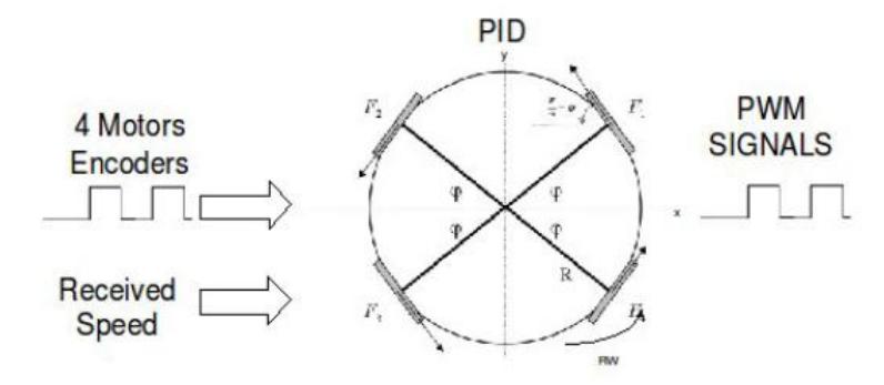
- Actual motor speeds are read from the motor encoders. From these, actual linear and angular speed vector of the robot are computed.
- The robot receives through the radio link the desired linear and angular speeds.
- There are three independent PID algorithms: one for linear speed in x, one for linear speed in y, and one for angular speed. They use the actual and desired linear and angular speeds to compute speed corrections for each motor. These speed corrections are used to compute the duty cycle of PWM signals for the control of each motor. An illustration of this process is shown in Figure 1.
Computation of motor speeds through multiplexing and Timer/Counter
One of the problems we faced last year was in speed computation for the motors. The encoders were attached to processor inputs that generated an interrupt at every pulse generated by each encoder. Since the frequency of interrupts was so high, the processor had little time to manage communications and the PID resulting in very slow control actions for our robots. We addressed this problem in the following way:
- We now use the Timer/Counter system of the microcontroller in order to compute the frequency of encoder pulses without needing interrupts.
- We implemented 4x1 multiplexor that allows us to use a single input for the four motors. Our program alternates the computation of speed for each motor intime.
5.4 Kicker Control System
Another issue we are addressing this year is the design of our kicker. So far we have pinpointed several issues in the booster of our kicker system that we have already addressed with promising results. Currently, our kicker is able to kick, although one piece of the design still burns randomly. Our plan is to solve all the issues in this area by the time of RoboCup 2013.
In order to kick the ball, we use a push type solenoid. Solenoid kicker system needs a high power supply. For size restrictions robots have four 7.4V/ 700mA batteries, equivalent to 31 Watts of power. With this amount of power we obtain less than the solenoid requires for a minimum performance. The main idea in power elevation is to store energy, then discharge it when solenoid is activated. To solve this power problem we implement a layered system as follows:
Voltage transformation The 14.8 dc voltage obtained from the batteries is increased using a voltage multiplier to reach 180 volts. The output is used to charge up a bank of capacitors. The converter is controlled using a control pin of the DSP with a relay and a transistor. The robot can kick approximately every 25 seconds.
Discharge and solenoid activation An infrared sensor system in the bottom of the robot senses if the robot has the ball. The microcontroller sends a high-level output bit when the robot is in score position. To discharge the capacitors into the solenoid, the Discharge layer uses both the microcontroller kick bit and the infrared ball detector output bit to discharge the capacitors. Because the capacitors charge level is very high, the robot discharges it using a power MOSFET. A signal from the microcontroller, is sent to the RELAY to control the flow of current through it and thus controlling the kick.
6 Research timeline for RoboCup 2012
In RoboCup 2012 we had a fully functioning team that was able to play in all the games. Our performance was still lower than we want, so this year we have addressed several issues and we still have a research agenda in order to reach a good performance in RoboCup 2013. The issues that we have addressed so far are: conflicts in interrupt handling in the microcontroller caused by highfrequency signals from motor encoders; and, power management in the booster for our kicker system; training and retention of team members.
In the coming months we will work on the following projects: addition of dribbler motor; applying recent design changes to the motherboard of our robots; fixing some trajectory control issues detected during the preparations for the qualification materials; integration of the motion planning system and the expert system that takes role decisions.
7 Conclusions
As a conclusion we revise the final status of the improvements made to the project before the deadline of this TDP. The sequence planner is in a viable state, we keep testing this module in order to get the robots into a more competitive state before the competition. Until this moment we have implemented the software in 4 of the 6 robots that we have and both divisions of the team, hardware and software, are joining their respective parts of the project.
8 Acknowledgements
This work is supported by the Asociación Mexicana de Cultura, A.C. and the Instituto Technológico Autónomo de México.
References
- RoboCup SSL, laws of the F180 league 2012. http://small-size.informatik.uni-bremen.de/rules:main.
- S. Zickler, T. Laue, O. Birbach, M. Wongphati, and M. Veloso. SSL-Vision: The Shared Vision System for the RoboCup Small Size League. RoboCup 2009: Robot Soccer World Cup XIII, pages 425–436, 2009.
- Ernesto Torres and Alfredo Weitzenfeld. RoboCup small-size league: Using neural networks to learn color segmentation during visual processing. In ENRI-LARS, Salvador, Brasil, 2008.
- Basu A. Elnagar, A. Local path planning in dynamic environments with uncertainty. pages 183 –190, Oct 1994.
- S. M. LaValle and J. J. Kuffner. Rapidly-Exploring Random Trees: Progress and Prospects. In Proc. Int. Workshop on Algorithmic Foundations of Robotics (WAFR), pages SA45–SA59, Hanover, NH, USA, March 2000.
- Micromo. http://www.faulhaber-group.com/uploadpk/e_201_MIN.pdf.