MCT Susanoo Logics 2013 Team Description Paper
Makito Ishikura, Ryo Itohara, Tomoaki Tsuchie, Kazuhiro Fujiwara
Matsue College of Technology 14-4, Nishiikumacho, Matsue-shi, Shimane, 690-8518, Japan
Abstract The MCT Susanoo Logics were joining into Japan RoboCup competition from 2011. All Our Robots with four Maxon 30 watts flat motors were totally designed by the team members and manufactured in the MCT factory. The AI control software was developed by C++. This paper describes mechanical and electrical systems, and control strategies of the MCT Susanoo Logics.
1 Team Outline
The MCT Susanoo Logics consists of the members of Department of Control Engineering, Electrical Engineering, and Information Engineering of Matsue College of Technology (Kosen). Our Robots with four Maxon 30 watts flat motors were totally designed by the team members and manufactured in the MCT factory. Chassis were processed with Mazak Space Gear 3 dimensional laser processing machine and omni-wheels were processed with Mazak CNC Turning Centers. Electrical circuits boards were designed with Eagle PCB software and cut with Mits PCB Milling System. The AI control software was developed by C++ in Qt Creator.
In February 2011, we visited Toyota National College of Technology, and were suggested design know-how by the member of KIKS. We thanks them. We started the development and joined into Japan RoboCup competition 2011. Our robots could not move at all, because of trouble of the wireless communication system. We improved both AI and hardware. Our robot got a point on a game in the 2012 competition, but did not reach the finals. Results of the elimination round was 0 win, 1 lose (against Skuba, Thailand) and 3 draws.
Table 1 shows our team member.
Table 1. Team members
| Name | Age | Department | Part in RoboCup |
|---|---|---|---|
| Makito Ishikura | 21 | Control Engineering | Robot's Micro Programming |
| Ryo Itohara | 21 | Control Engineering | Chassis Design and Development |
| Ryo Kusaka | 21 | Electrical Engineering | Electrical Circuits Design and Development |
| Takahiro Suyama | 21 | Information Engineeirng | Robot's Micro Programming |
| Tomoaki Yoshida | 21 | Electrical Engineering | Chassis Design and Development |
| Satoshi Takata | 20 | Electrical Engineering | Chassis Design and Development |
| Yuji Horie | 20 | Electrical Engineering | Electrical Circuits Design and Development |
| Shota Aoki | 19 | Electrical Engineering | Electrical Circuits Design and Development |
| Tomoaki Tsuchie | 19 | Information Engineeirng | AI Software Development |
| Kazuhiro Fujiwara | 19 | Information Engineeirng | AI Software Development |
| Yuta Notsu | 18 | Information Engineeirng | AI Software Development |
| Daichi Miura | 18 | Information Engineeirng | AI Software Development |
| Keita Uchida | 18 | Information Engineeirng | AI Software Development |
| Katsutoshi Fujiwara | 17 | Information Engineeirng | AI Software Development |
| Shin Miura | 17 | Information Engineeirng | AI Software Development |
2 Hardware Outline
Fig.1 shows the external shape of MCT Susanoo Logics 'Robot. Each 50 mm in diameter omni-wheel is driven by a Maxon EC45 Flat 30W brush-less DC motor with a gear ratio of 6:17. A ring type rotary encoder for measuring the rotation speed of the motor is attached to the motor axle to ease the maintenance and repair(Fig.2).
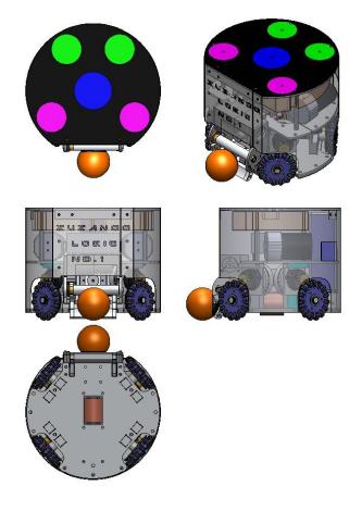
Fig.3 shows the assembly of an omni-wheel. The main wheel made of nylon 901 lowers the weight in 40 percent comparing with a duralumin wheel. An omni-wheel has fifteen sub wheels. Each sub wheel consists of two one-side flange bearings with o-rings. This structure shortened the assembly time.
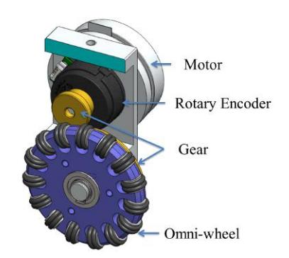
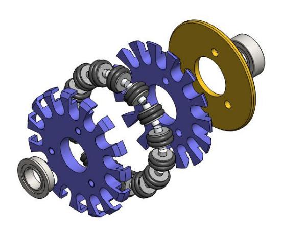
Fig.4 shows the dribble device and kick devices. The width of the dribble device is 70 mm. A Maxon EC-max 22 brush-less DC motor drives the dribble bar of 13 mm in diameter for dribble action. The dribble bar is placed about 40 mm from the field. At the pass receiving, the bar moves up about 3 mm to absorb the kinetic energy of the ball for preventing rebounding. The Kick device accelerates the ball speed to 8 m/s by two 400 turns of solenoids..
Table 2 shows the robot specification.
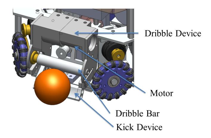
Table 2. Robot specification
| Height | 148.5[mm] |
|---|---|
| Diameter | 177[mm] |
| Weight | 2.5[kg] |
| Maximum robot speed 3[m/s] | |
| Maximum ball speed | 8[m/s] |
| Ball coverage | 20[%] |
3 Electrical System Outline
Fig.5 shows the electrical block diagram of a robot. A 4-cell lithium-polymer battery (14.8 V, 2500 mAh) supplies current to the main, 5 motor drivers and the kicker and driver boards. On the Main board, a XBee 802.15.4, 2.4 GHz wireless communication module is installed. The baud rate of the XBee is set to 115200 bps. The module receives instruction data from the AI computer at the interval rate of 1 / 60 second. The AI computer sends the instruction data of machine velocity and direction, angular velocity, and command for the dribble and kick device. A Microchip dsPIC33FJ32GP202 with clock frequency of 80 MHz is implemented as the main CPU of the robot. The main CPU calculates motor rotation speeds, and sends command to 4 motor drivers via I2C communication line.
The Main board has voltage regulators for power supply. A V-infinity V7805- 1000 DC to DC converter is adopted for 5 V line and a 3-terminal linear regulator is used for 3.3 V from 5 V.
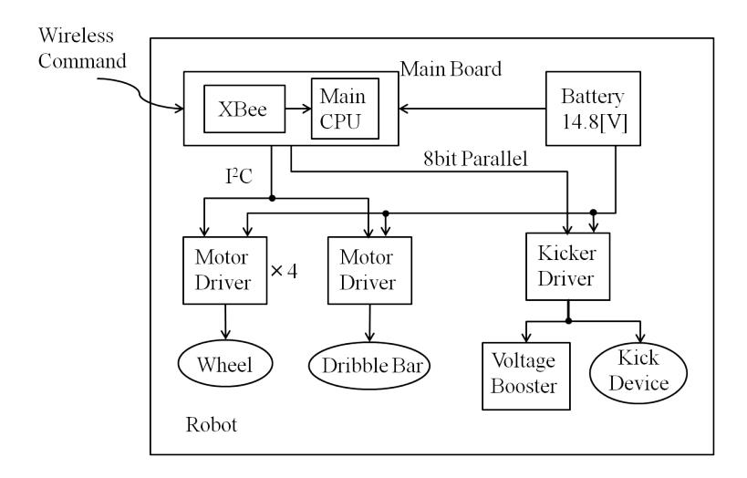
Fig.6 shows the diagram of a motor and a driver. A motor driver consists of a PIC controller and a 3-phase full bridge with N-channel MOSFETs drives Maxon brush-less DC motor for wheels and a dribble bar. Microchip dsPIC33FJ12MC202 on the motor driver receives the command from the main CPU and outputs 3-phase PWM pulses for the bridge. For detecting the rotation speed of the motor, a US Digital E8P (1440[PPR]) rotary encoder is used. The Proportional-Integral (PI) controller is adoped for the motor speed controller.
For the dribble bar, the encoder is not used, since precise rotation control is not required.
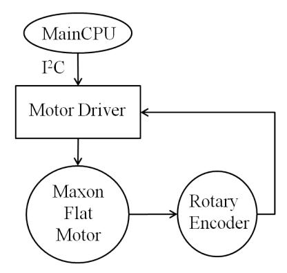
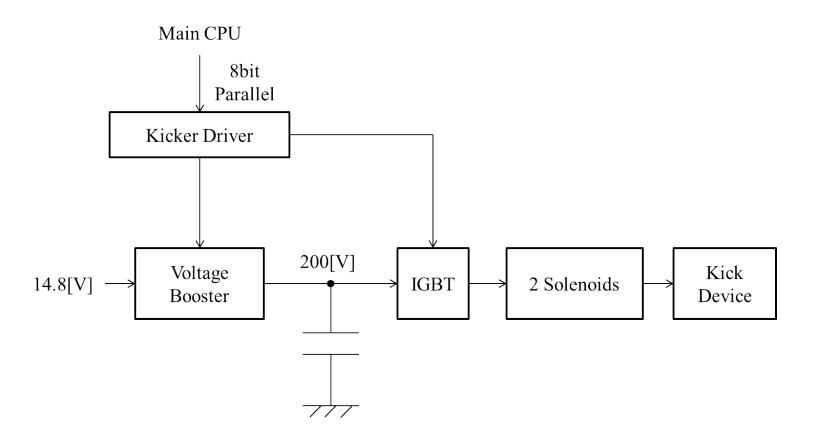
Fig.7 shows the diagram of the kick device and a driver. A voltage booster has a chopper circuit for the boost converter charges 2 * 2200 uF capacitors to 200 V within 3 seconds. A capacitor charger, Linerar Technology LT3750 controls the boost converter. For adjusting the strength of the ball kick, the main CPU controls the gate-on time of a IGBT for discharge the capacitors.
4 Software Architechture
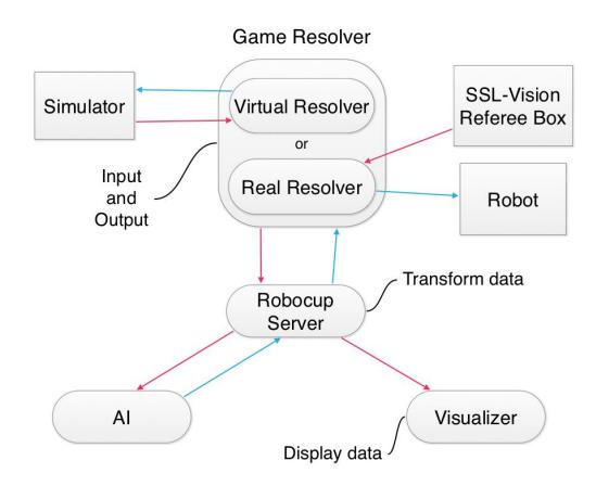
Our software architecture is shown in Fig.8. Game Resolver is taken charge of AI's Input/Output. It has two kinds of programs. One is Real Resolver which is used in real game. Another is Virtual Resolver which is used in simulation game.
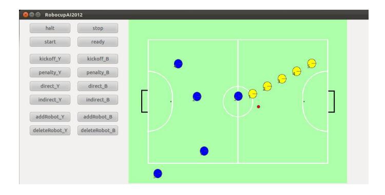
Fig.9 shows the Visualizer. We use Parsian Robotic's grSim as the simulator. We thank this. Robocup Server helps the communication between Game Resolver and AI & Visualizer. Visualizer graphically displays robots and ball position. We have developed it by Qt(GUI framework for C++). Visualizer runs quickly.
The program runs as shown below.
- When the Game Resolver receives a game-data-packet from Referee Box and SSL-Vision or Simulator, Game Resolver re-sends it to the Robocup Server.
- Then Robocup Server receives a game-data-packet from Game Resolver, Robocup Server transforms it properly and re-sends it to the AI and Visualizer.
- When AI receives a game-data-packet , the AI decides a next strategy from that data and sends a strategy-data to Robocup Server. Visualizer receives game-data and graphically displays it.
- Robocup Server receives a strategy-data from AI , then Robocup Server transforms it properly and sends it to Game Resolver.
- When Game Resolver is :
- – Real Resolver : data sends to robots.
- – Virtual Resolver : data sends to the Simulator
- Goto 1.
5 AI Architecture
(This section contains subsections below)
5.1 AI Development and Comb Library
In the Real time team battle game like Robocup, the AI is tend to be complex. Therefore we have developed a library" Comb "to describe the AI simply. Comb is C++ library. It provides DSL(Domain-Specific Language) for describing Task and Command. It also provides frame work for AI like Fig.10.
" Task " is a temporary purpose of team. " Command " is a gathering of order to robots.
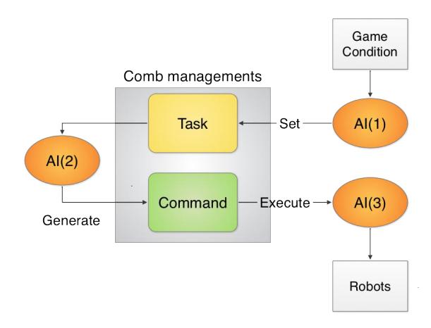
By this structure , AI description is divided by three steps below:
- To Set Tasks to team
- To Generate Commands based on Tasks
- To Process the result of executing Commands.
By this division of AI , we can develop AI effectively.
5.2 DSL for describing Tasks and Commands
Comb enable us to describe complex Task-Command by combining some simple ones.
The way of combination, sequential executing , conditional branching, repeating, and executing two Commands or Tasks on parallel and synthesize the result.
And the inner DSL provided by Comb , the AI programmer can describe combination intuitively.
For example,
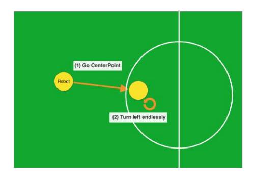
Command com(While( ! isInCenterCircle( ) )[goTo(CENTER_POSITION) ] >> While( true )[turnRight( 0.1 ) ]);
This C++ code generates Command expressing the orders like Fig.11.
Using this DSL , we can describe AI simply.
And this is C++ inner DSL. So we can use C++ debugger and execute very quickly.
5.3 Annotations
Our Library"Comb"'s name is from comb and abbreviate of"Combination". Comb is deeply related to Susanoo , the one of the deity of japanese mythology.
Considering our team 's name and library 's role, we have named the library " Comb ".
References
(No references section in the original paper)