NEUIslanders 2013 Team Description Paper
Ali Erdinc Koroglu, Rahib Abiyev, Nurullah Akkaya, Ersin Aytac, Mustafa Arici, Kamil Dimililer
Department of Computer Engineering; Advanced Research Center; Department of Mechanical Engineering; Department of Electrical and Electronics Engineering
Abstract This paper describes the current development status of the RoboCup Small-Size League robot team NEUIslanders. NEUIslanders SSL robot soccer system is designed under the RoboCup 2013 SSL rules so as to participate in RoboCup 2013. This year we have made major changes to our 2012 design, all hardware modules have been redesigned.
Introduction
NEUIslanders is an interdisciplinary team of students at the Near East University. The team is currently seeking qualification for RoboCup 2013. Since last year, it has made significant developments of its team of autonomous soccer playing robots. This paper will outline the progress in implementation of the current model of robots.
Our,(NEUIslanders) robot system consists of two major components: the robot hardware and control the software. The software makes strategic decisions for the robot team by using information about the object positions from the vision system.
In Hardware section, we give the details of the mechanical parts our robots. The basic mechanical components of the robots are described in detail.
In Software section, we give implementation details of our control software. These include the software for decision making system, path finding and motion control, finally Conclusions are given in the last Section.
Hardware
The mechanical designs and parts of our robots are changed 100% this year. Last year we used three wheeled design due to lack of Maxon motors. This year we are using four wheels. All of our mechanical parts are manufactured in high precision CNC machines. The robot diameter is 175 mm and height of 150 mm.
Chassis
We manufactured our chassis from plexiglass last year. Since we did not have any experience we thought the plexiglass chassis will be rigid enough to play the games. This year we are using 3mm thick 7075 aluminum for the chassis. Wheel orientation is dramatically effecting the robots speed and acceleration. After calculations we gure out that 45 degrees at the rear and 33 degrees at the front wheels with respect to the horizontal axis is the best orientation that ts our robots.
Omni-Wheels
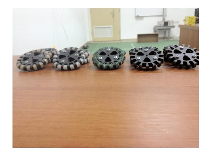
To improve our performance we have been working hard on our omni wheel design. For the last 2 years we tried five different omni wheel models with different diameters. We reduced our wheel diameter from 62mm to 50 mm this year. The wheel is manufactured from 7075 aluminum.
This year our wheel design consists of three parts. Wheel hub has an inner canal for the ring to add rollers which are 10 mm in diameter. The are 15 rollers on our omni wheel. The wheel cover is just to cover the inner part of the wheel. Also last year we used external gear to couple with the pinion gear on the motors. This year we are using internal gears which are placed on the back side of the wheel with 72 teeth on them. The pinion which is going to couple with this inner gear has 20 teeth on them. Both of the gears are manufactured from brass. This year our gear ratio is also improved from 5:1 to 3.6:1, that's why our robots are moving faster than the last year.
Mid-plate
The mid-plate is important for the general rigidity of the robot. Last year mid plate is very thin 1 mm thick plexiglass. This year two L shaped 3 mm thick 6062 aluminum connecting motor mounts each other and the electronical parts are mounted on them.
Motor Mounts
We used 6062 u-shaped aluminum motor mounts and mounted the motors inside the u for the last two years. This year we are making a radical change in our motor mount and our motor mount is I shaped. We are using 3 mm 7075 aluminum for the motor mount and our calculations shows us that the bending moment is higher. Also to take the center of gravity lower 10% of the motor is going through a hole in chassis. Also the drive shaft housing was brass last year, this year we are using a ball bearing placed right in the aluminum motor mount.
Kicker
Last year we only had a one kicker which can only chip kick the ball. This year we are using 2 kickers. Chip kicker has a custom made flat solenoid, a steel plunger placed in the solenoid and like last years design the plunger hits a swing which has 45 degrees on the bottom. The other kicker has a round solenoid. The kicker is made of 5 different parts. An e clip placed on the back to limit the kicker made from aluminum. In the middle only a very small part is made from steel which is inside the solenoid. The front is consists of 2 different parts. First an aluminum part is connected to the steel rod. The front part is manufactured from a flat part 7075 aluminum and it has a little curvature to center the ball for kicking directly to the target.
Software
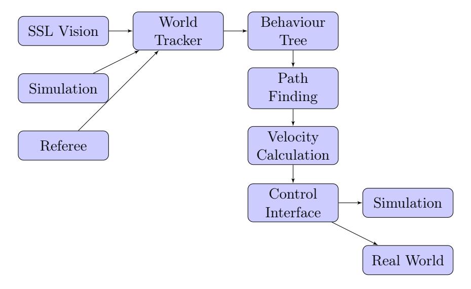
The control system of the team has 4 major modules which includes, world tracking module, decision making module, path finding and local obstacle avoidance module and control interface.
Tracking module is responsible for keeping track of the current state of the game, besides what vision server sends us, we also keep track of certain other things such as robot speeds, robot headings, ball speeds and ball headings. These parameters are alter used by the implementations of various behaviours.
Decision making (DM) module is a behavioural control algorithm that has a tree structure. Nodes of a behaviour tree operate using certain behavioural rules, allowing us to easily design complex parallel behaviours. Its implementation details are given in section Behaviour Trees.
Once a decision is made to move a robot, path finding module is used to find quick and feasible solutions in rapidly changing dynamic environment, using a combination of RRT planner and local obstacle avoidance ant calculates robot velocities that will guide them through their paths. Its implementation details are given in section Path Finding.
Finally calculated velocities are sent to the robots using the control interface which either sends commands to the robots via the wireless link or sends commands to grSim via UDP.
Behaviour Trees
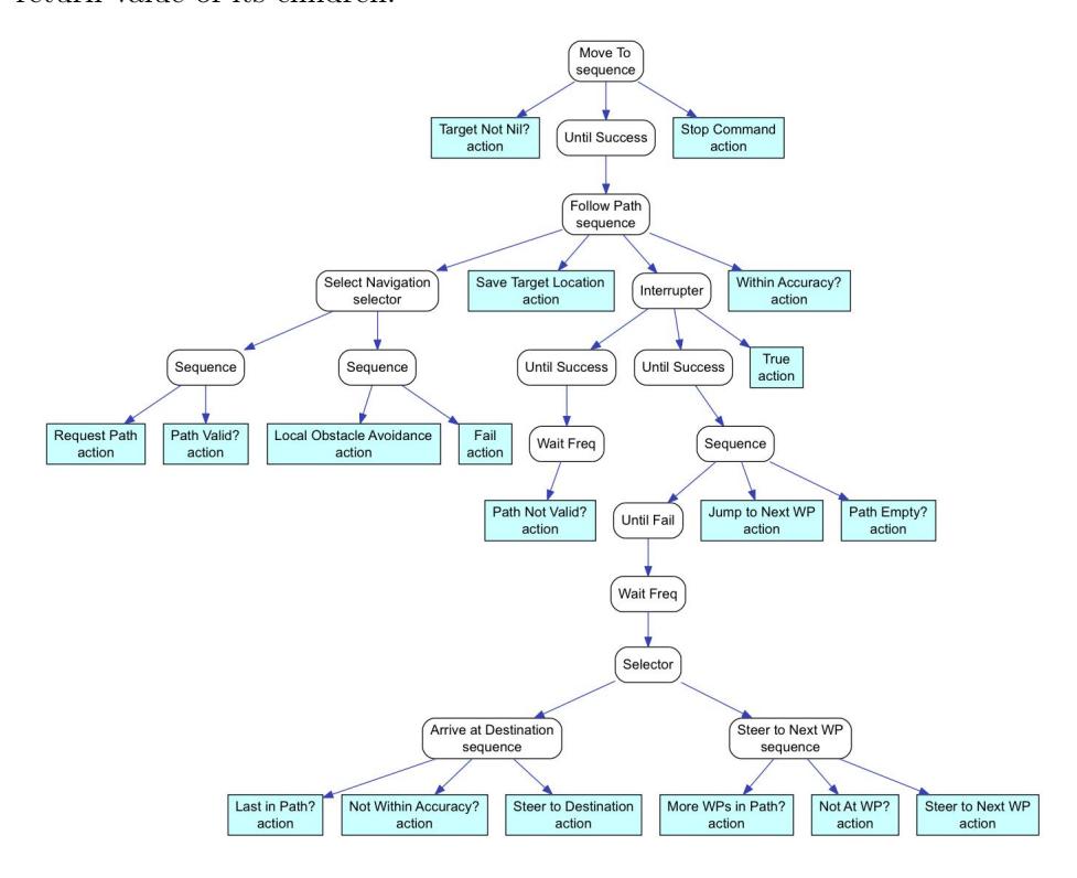
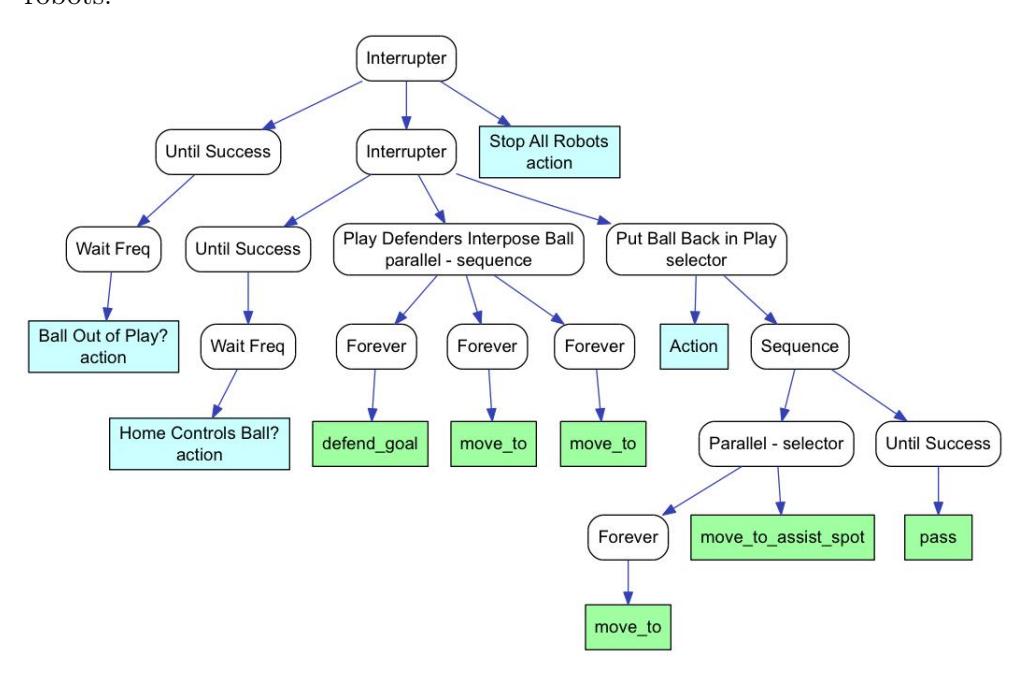
Our software architecture relies heavily on behaviour trees. Behavior trees combines a number of AI techniques such as Hierarchical State Machines, Scheduling, Planning, and Action Execution. Their strength comes from the fact that it is very easy to see logic, they are fast to execute and easy to maintain. which makes them suitable for representing complex and parallel behaviors.
Behavior trees allow us to piece together reusable blocks of code which can be as simple as looking up a variable in game state to sending a motor
Path Finding
In order to get our robots from a to b without colliding with other robots move-to relies on two techniques, first it will look for a path using a RRT planner in the case of a path is not found we switch to local obstacle avoidance, which gives the robot the ability to maneuver on the field by dodging around obstacles. It works by drawing a line from the robot towards its heading proportional to its speed. Then we check if any any of the robots on the field intersects with this line, closest robot that intersects with this line is considered a threat, in order to maneuver around the obstacle two velocities are calculated one that steers it around the obstacle and another that applies a breaking force.
Motion Control
Robot's drive system is made up of four omni-wheels mounted at angles, which allows movement in any direction, at any angle, without rotating beforehand. For an omni-wheel robot to translate at a certain angle, each motor needs to go at a certain speed with relation to the others. This is obtained using the following equation [5], (All the angles of the motor axis are measured relative to the x direction in the coordinate system of the robot. Each rotating the robot in counter counterclockwise direction.)
$$\begin{bmatrix} v_1 & v_2 & v_3 & v_4 \end{bmatrix}^T = \begin{bmatrix} -sin\theta_1 & cos\theta_1 & 1 \ -sin\theta_2 & cos\theta_2 & 1 \ \vdots & \vdots & \vdots \ -sin\theta_n & cos\theta_n & 1 \end{bmatrix} \times \begin{bmatrix} v_x & v_y & R_W \end{bmatrix}^T$$
Here $V_x$ , $V_y$ , and $R_w$ is the intended direction of travel of the robot calculated by the DM and $V_1$ $V_2$ $V_3$ and $V_4$ are the individual motor speeds. Within the software all speeds calculated are in $\frac{meters}{secs}$ , finally individual motor speeds are converted to $\frac{rads}{secs}$ using the following formula,
$$\omega = \frac{2 \times v}{d} \tag{2}$$
where,
- $\omega \to \text{angular speed} \left( \frac{rad}{sec} \right)$
- v $\rightarrow$ linear speed ( $\frac{meter}{sec}$ )
- $d \rightarrow$ wheel diameter (meter)
And sent to the robots every $\frac{1}{60}$ of a second through the wireless link.
Conclusion
In this document, we have shown the current development stage of the NEUIslanders SSL robot soccer system. We have emphasized the major changes in our mechanical design and software architecture. Our new design will enable the system to react quickly to the changes in the game state, as well as perform more efficiently than the design we have developed in 2012. The strategy system is currently still under heavy improvements.
References
[1] James Bruce and Manuela Veloso. Real-time randomized path planning for robot navigation, 2002. [2] Alex J. Champandard. Getting started with decision making and control systems, ai game programming wisdom 4, section 3.4, pp. 257–264, 2008. [3] Chong-U Lim. An a.i. player for defcon: An evolutionary approach using behavior trees, 2009. [4] Craig Reynolds. Steering behaviors for autonomous characters, 1999. [5] Raul Rojas. Holonomic control of a robot with an omni-directional drive, 2006.