Parsian (Amirkabir Univ. Of Technology Robocup Small Size Team) Extended Team Description for Robocup 2013
S.Mehdi Mohaimanian Pour, Vahid Mehrabi, Alireza Saeidi, Erfan Sheikhi, Masoud Kazemi, Ali Pahlavani, Mohammad Behbooei, Parnian Ghanbari
Mathematics and Computer Science Department, Amirkabir Univ. of Technology; Mechanical Engineering Department, Sharif University of Technology; Mechanical Engineering Department, Amirkabir Univeristy of Technology; Electrical Engineering Department, Amirkabir Univeristy of Technology; Computer Engineering Department, Amirkabir Univeristy of Technology
Abstract This is the extended team description paper of the Robocup Small Size Soccer Robot team "Parsian" for entering the Robocup 2013 competitions in Netherlands. In this paper we will represent detailed description of our robots' hardware design, as well as the software architecture in detail with focus on new improvements that have been made since last year. Improvements and developments that seemed innovative and useful like modifying and fixing Maxon EC-45 Motors, improvements on path planing and motion planing will be discussed in detail.
Introduction
''Parsian" small size soccer robots team, founded in 2005, is organized by electrical engineering department of Amirkabir University of Technology. The purpose of this team is to design and build small size soccer robots team compatible with International Robocup competition rules as a student based project.
"Parsian" team consists of nine active members from electrical, mechanical and computer science backgrounds. We have been qualified for seven consequent years for RoboCup SSL. We participated in 2008, 2009, 2010, 2011 and 2012 RoboCup competitions. Our most notable achievements was Parsian's first place in RoboCup 2012 SSL's Passing and shooting technical challenges and forth place in RoboCup 2012 SSL competition.
In this paper we first introduce our robots' hardware (section 2). Our new mechanical modification for this year and Macon motors improvements 2.1 and our electrical design will be covered in section 2.2. Section 3 explains our software framework including high path planning algorithm and high level control algorithms.
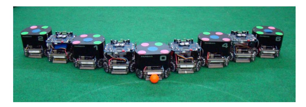
The Robot's Hardware
Mechanical Design
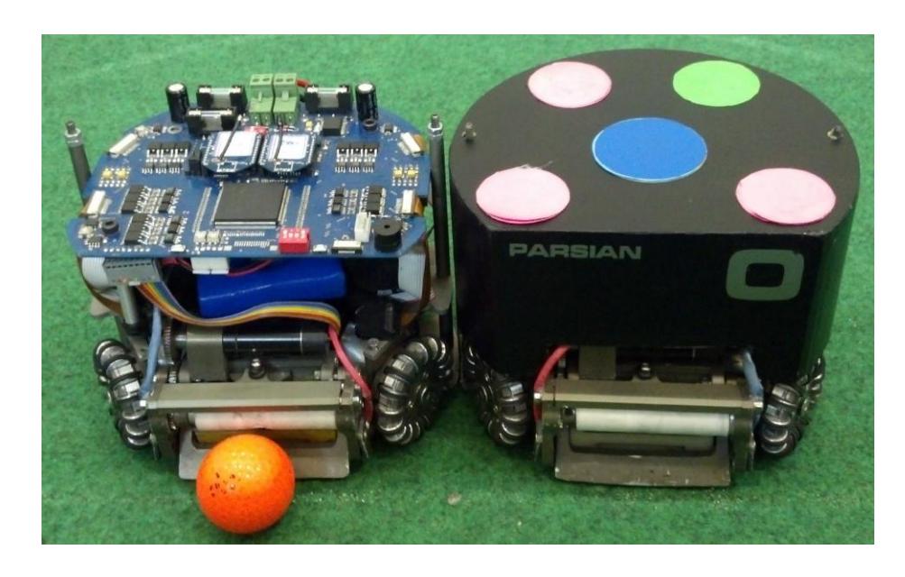
In this section we are going to describe the mechanical system and design procedure of our robots which consists of drive system, dribbler, kickers and so on. The dimension and other major parameters of our robots are described below. Figure 2 shows our robots with and without cover.
| Robot Diameter | 178 mm |
|---|---|
| Robot Height | 138 mm |
| Ball Coverage | 19 % |
| Max Linear Velocity | 4.1 m/s |
| Weight | 2.2 kg |
| Maximum kick speed | 15m/s |
| Maximum chip kick distance | 7.0 m |
| Maximum passing ball speed catching 6m/s |
Some important section of our robots mechanical sections would be described in following section.
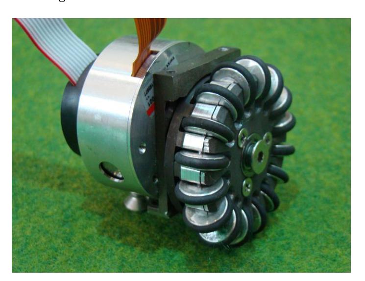
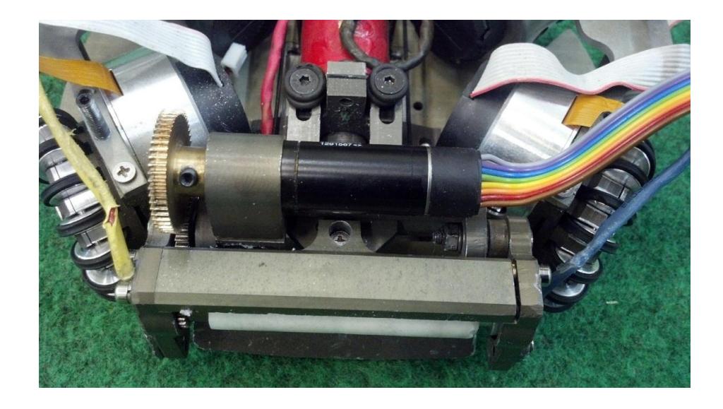
Driving System : For the driving system we use 30 watts Maxon EC45 12volts motors that are mounted to the wheels with an internal gear with ratio of 3.6:1 (76:21). The gear is made of spring alloy steel with high tensile strength and 50HRC hardness and thickness of 3mm using wire cutting procedure. Whole driving package is shown in Figure 3
Brushless motors, Maxon EC45: Always optimized actuator (motors) selection for a system is a significant factor in system reliability, costs and performance.
In one hand over design alternatives make extra weight that needs more volume and theyre more expensive and sometimes mismatching with other components can make more faults in system. So with this way system need regularly maintenance. On the other hand selecting an alternative with lower reliability means this component should working in zones which are over the nominal operation area. Often this means more heat and other types of energy losses; because most components have some restriction for operation in different states.
Likewise selecting a proper motor for small size soccer robot is a concern for our team. We have a robot that should work properly in highly dynamic situations. This robot should execute commands with precision and accuracy. Total smallest errors in an open loop control system if can't be corrected, makes irreparable errors in output.
The restrictions that mentioned above are mechanical and electrical restriction. Each one alone and coordination between them can make an incorrect design or choice. Here we mention some of regular Maxon EC45 Design faults that we tried to fix.
Mechanical restrictions: These limitations include Torque transmission, speed, stress components and etc. for example motor EC-45 had some of this limitation that has been modified over time.
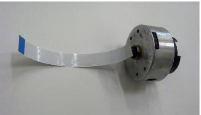
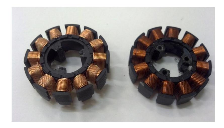
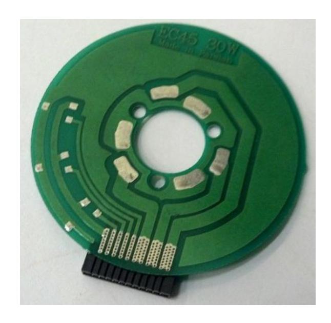
Problem : fracture in connections between the coil and main structure of motor that causes the hall sensors to brake.
Solution : select appropriate connection for safe torque transfer
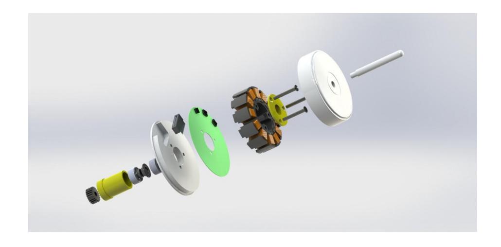
Problem : Rotational component depreciation such as bearings
Solution : Coaxial and fix components with appropriate locating.
Electrical restrictions: About optimal design in electrical there are some considerations such as modular design, safe and reliable design and etc. For the example above we have modified some parts for achieving to a safe design.
Problem : tearing the motor cable over time.(Figure 4)
Solution : modular connections.
Ball Control and Suspension System: One of our major changes in robots are in the dribbling and suspension system that have been replaced from one degree of freedom mechanism to two degrees of freedom system. This increase in DOF helps us to calibrate the ball position and spin back speed easily and more efficiently. It can also hold the ball stronger and damp the energy of the passing ball without losing it more effectively. With use of simulation and measurements we find out that the maximum pass speed that this system can catch is up to5m/s.
Our future plan for improving the suspension system is to control one of the DOFs with a servo motor in order to calibrate it automatically.
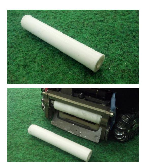
Dribbling and Suspension actuator for the spin back module is 30watts Maxon EC16 12volts motor mounted to the gearhead with total gear ratio of 3.6:1 (36/10) that speedup the silicon-tube coated spinner up to 12000rpm. We made coated silicon hollow bar using a mold filled with silicon raw material. Using this method we eliminated our problem about finding a proper material for spinner cover. Here is a picture of our silicon hollow bar made.
Its friction coefficient is about 0.8 that is appropriate for our usage. Both side of dribblers arm are equipped with the cover to protect the ball detection sensors from damage.
![[Problem: fracture in connections between the coil and main structure of motor that causes the hall sensors to brake]](/tdps/soccer_smallsize__2013__Parsian/_page_3_Picture_5.jpeg)
![[Problem: fracture in connections between the coil and main structure of motor that causes the hall sensors to brake - continued]](/tdps/soccer_smallsize__2013__Parsian/_page_3_Picture_6.jpeg)
![[Solution: select appropriate connection for safe torque transfer]](/tdps/soccer_smallsize__2013__Parsian/_page_3_Picture_8.jpeg)
![[Solution: select appropriate connection for safe torque transfer - continued]](/tdps/soccer_smallsize__2013__Parsian/_page_3_Picture_9.jpeg)
![[Problem: Rotational component depreciation such as bearings]](/tdps/soccer_smallsize__2013__Parsian/_page_4_Picture_1.jpeg)
![[Solution: Coaxial and fix components with appropriate locating]](/tdps/soccer_smallsize__2013__Parsian/_page_4_Picture_3.jpeg)
Electrical Design
Our electronic system consists of two electronic boards, the main board and the kicker board. The main boards platform is based on a single chip Xilinx Spartan XC3S400-PQ208 FPGA which in charges for wireless communication (Send and Receive), BLDC motor driving with current control, executing the low-level control loop and sending control signals to the kicker board. The kicker board consists of a power section (Charging and discharging MOSFETs) and a voltage divider for voltage feedback of capacitors.
Battery and Power Supply Each robot uses 4-cell 2000mAh lithium polymer battery as a power source. There are three main power lines for kicker board, motor driver and logic devices. These lines are protected with different current rating fuses. There are four voltage regulator which supplies 1.2v, 2.5v, 3.3v and 5v for logic circuit. In the last year we use series regulator but we replace it with LM2576 switching regulator because of its high efficiency.
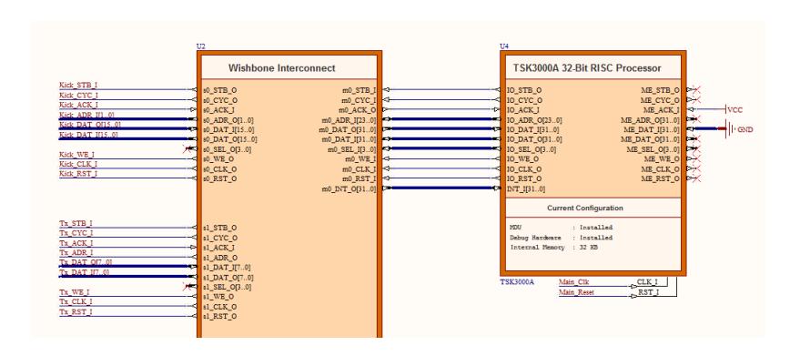
Main Processor FPGA devices are mainly appropriate for parallel algorithms implementation. Due to less power consumption, simpler board layout and fewer problems with signal integrity and electromagnetic interface, we preferred to have both microcontroller and FPGA array based features combined in one chip. Consequently quadrature decoder, PWM generation, BLDC sequence generator modules and serial communication are implemented in a hard CPU core which is dedicated part of the integrated circuits, whereas sensors data decoder, controller loop handler and other modules are implemented in a soft CPU core which utilizes general purpose FPGA logic cells. We implemented a TSK3000A based soft processor on the FPGA. We use Altium Designer software to change processor or modify the code running on it. To debug a phase of a design we utilize a standardized debug interface via JTAG bus. The Soft core is connected to the other blocks via wishbones. These blocks are BLDC Controller, Kick Block and Communication Block which are developed using Verilog language. (Figure 10)
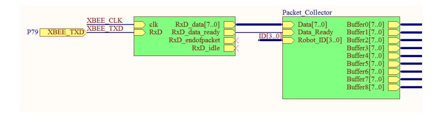
Communication We are using two XBee modules for bidirectional wireless communication. One XBee is for receiving data and commands from the Host PC and the other one is for sending data such as battery voltage, kicker sensor's status. Last year, we were using 57600bits/s as our wireless baud rate and this year we have increased it to 115200bits/s for less command sending interval. Each packet consists of 9 bytes including robot's ID, Kick or Chip speed, Vx, Vy, W and etc. Each robot receives these packets and selects the packets which its ID is as same as robot's ID. In the past, we were using an interrupt which was showing that new packet is received or not. So by increasing the amount of robots, the interrupt request rate was increasing. Now we have developed a Verilog block in FPGA which receives data packets from Receiver block and matches the ID of the packet with robot ID and then loads the data on output buffers. So every time that the soft core needs to read the commands, should read these buffers.(Figure 11)
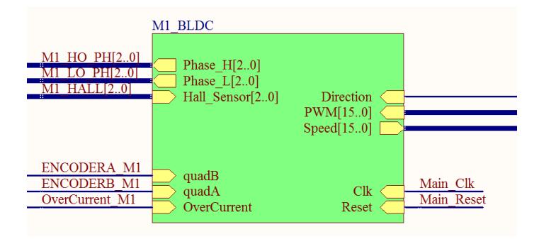
Motor Driver Each motors BLDC driver unit consists of two modules; a FPGA based digital circuit as main controller and a power driver circuit. The controller receives Hall Effect sensors data, and then generates proper control signals for each motor.
The power driver circuit is a three phase inverter circuit using complementary N and P channel power MOSFET in each phase. These MOSFETs are driven by TC4427 MOSFET driver to minimize switching loss. The three phase inverter bridge is fed with signals from FPGA to provide commutation for each motor. These signals are ANDed with the PWM signal to vary the average voltage applied to the motor winding and over current signal to limit the current flow of each motor.(Figure 12)
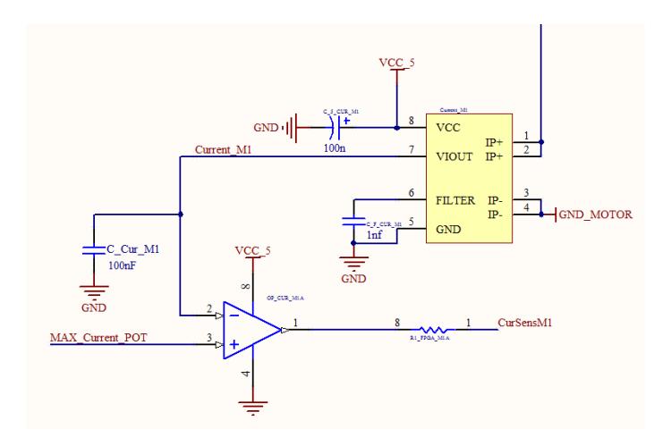
Motor Overcurrent Protection We use two over current protection manner to protect a BLDC from a receiving more than an exact Ampere of current. In the first method if an over current state is noticed by the software through the real-time reading of current sensors data, the PWM duty cycle will be narrowed up to the normal situation. In the second method a simple motor over current circuit is employed to cut the motor from its power supply when the over current situation is occurred. A current sensor measures the input current and yields a corresponding voltage signal at its output. This output is connected to the input of an analog comparator, with the other input coming from a reference voltage source of specified ampere of current to be created. If the output of the current sensor is greater than the specified value, the comparator will output the signal. This signal is then hooked into the FPGA and if over current occurs, the FPGA changes the motor signals so the motor will be turned off until the current decreases.(Figure 13)
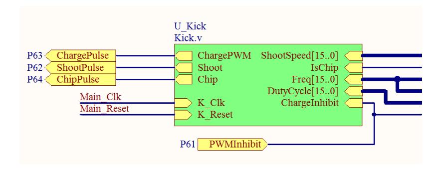
Kicker Board To decrease the size and weight of the kicker board, this year we have redesigned the kicker board by means of using new electrical components. The kicker board continuously charges two 2200 F 180V capacitors connected in parallels. The current design is based on DC to DC boost convertor circuit which utilizes a power MOSFET to discharge the stored energy into two solenoids. To increase the resolution of kick/chip speed we have designed a VHDL block which moderates the kick speed. With this new feature, kick/chip speed would be continues and this can be regulated with a high accuracy.(Figure 14)
Low Level Control The control commands are sent to the robots from the remote Host PC, contains velocities of robot along x and y axis and angular velocity of the robot. The quadrature decoder units implemented on FPGA decode each motors attached encoders signals. These decoders count digital pulses and calculate the speed of each motor. If the robot receives the velocity type command, the robot velocities are calculated by means of the transformation of four motors rotational speed. The desired velocity commands and the current calculated velocities are then fed into a cascade control system. Robot velocities as primer variables are controlled by adjusting the set point of each motors rotational speed as related secondary variables controller. A discrete PID controller acts as primary loop controller, which controls the robot velocities. A discrete PI controller acts as secondary loop controller, which reads the output of primary loop controller as set point, then the reference rotational speed of each motor is calculated using the transformation matrix. When the reference rotational speed is given to each motor, the PI controller generates the PWM control signal. Then the robot can reach its desired motion. Obviously if the robot receives the motor rotational speed type command, just the secondary loop controller performs the control action. Reasonably the robot has slip between the wheels and the ground in some amount. In absence of a sensor that measures the robot velocity, this slip cause an error between actual motion and the desired one. By means of an extended Kalman observer for state estimation which is implemented at the high level control loop, this error will be compensated. The performance of the compensation depends on how well the robots velocity is estimated by the extended Kalman.
Planner
In this section we skip most parts of our planner and just describe our new path planner with focus on problems using RRT path planner.
Dynamic Path Planner
This year we decided to create a Dynamic Environment Path Planning algorithm and as the RRT algorithm is the best algorithm for path planning in none discrete environment [1][2], we decided to implement it based on RRT instead of dividing the playground to discrete grid , so we reimplement our ERRT path planner and add some new features to that, and it became a new path planner consisting these new features.
The first step in having better path planner with RRT path planner is to consider the field a little bigger, as you know there are some situations that RRT planner cant find a path inside the field for that situation , so you can let the robot to cross out of the field and find the path to it's destination. this situation mostly happens when game start near corner of the field and the crowdedness of the robots don't let the RRT find any path inside the field.
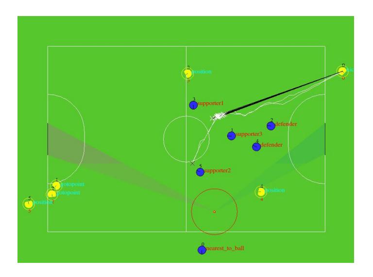
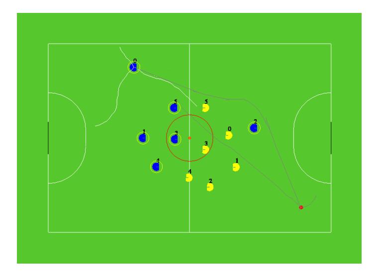
Next step in having better path, is not only start generating path from robot to destination, but also try to find another path from destination toward the robot, then try to connect the best branch of either RRTs and create the nearest path to your last path (called WayPoint cache in RRT algorithm) . this will help to find a better path in fastest possible way in deadlocks and when there's just a narrow path toward the destination and it will help to find the path with least maximum nodes limit so that we have limited our maximum extension nodes to 100 point for a path and it never misses finding a path when there's actually a path even narrowest ones.(Figure 15)
One thing that should be considered in using RRT path planner is that the result of RRT path planner is not an straight line (since it is extending toward some random points in any direction by extend step which is not that much long) so for having a better path planner you should create the longest straight path from output result . you can see how to create that in Figure 16 .
The other thing that bothers the robot to follow the exact generated path is that the RRT result could be fracture during the path and if this fracture is at the middle of path and robot reaches that point with maximum velocity , or a velocity that doesn't allow the robot to stay on the path while changing it's direction, it will cause the robot to deflect from the path and go through an obstacle or have a bad motion during cruise.
for solving this problem , we have tried so many heuristics , the best two methods for solving this problem will be discussed :
One method to overcome the mentioned problem is generating an smooth path with RRT , which can be done during extension of branches by limiting the angle between the generated branch by the time and the new extension that is going to be added . this method will give an smooth path and a path that have a great curvature instead of fractures. but unfortunately this method has some difficulties such as increasing robots travel time for reaching to a destination and the biggest problem is that staying on the past road and using Waypoint cache is too difficult .(Figure 17)
Another method for solving this issue is limiting the maximum velocity of the robot by considering the angle of fracture and the distance to reach that .
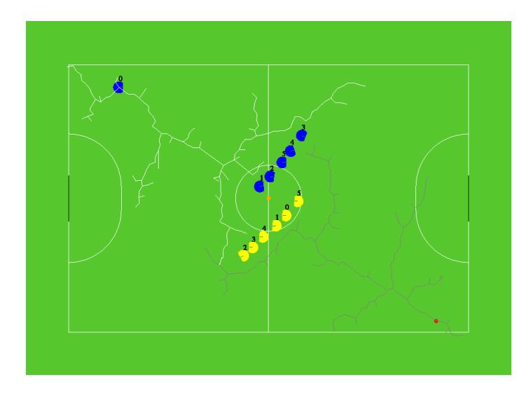
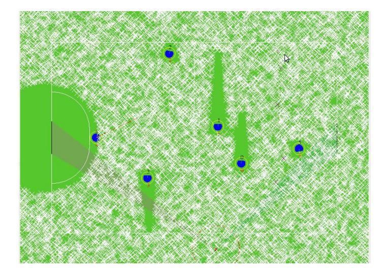
The last step to have a dynamic path planner is to not only avoid the current place of the obstacles but also avoid the possible places that an obstacle could be in future and by the time we reach them , for this purpose we create some virtual obstacles from moving obstacle toward its velocity direction. the number of these virtual obstacles and size of them depends on the velocity of the obstacle (other robots in field) . In Figure 18 you can see moving robots and the virtual obstacles toward their velocity.
Motion Time Estimation: The other problem in real time motion planning is calculating the time to reach the target and find out when we reach to any point during the path specially when the robot follows a generated path instead of an straight line , for this purpose we have designed a simulator that simulates the progress to the end of the road in an infinite loop and creates a motion profile witch shows the exact time that robot reaches to any point of the path and the exact velocity of the robot in that point. all we have to do afterward is following that profile .
High Level Planner
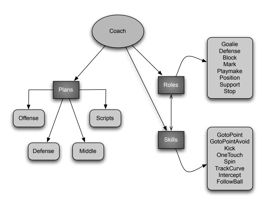
The Coach layer is the first step in the high level planning (decision making) loop. Choosing a formation for the team is done prior to any other decisions, in this year we have another layer beside Coach layer which is called strategy selecting layer, According to policies, that are a mixture of manual configurations and game-state dependent updated values, each cycle the strategy selector layer decides the team's formation. then coach assigns each agent to nearest role decided by strategy selector. Therefore, each agent takes part in one of the main plans: defense, midfield and offense.
In last year we have changed our high level planner a bit and added a layer called Plans , in our game-On play we use this method which contains 3 main plans as mentioned , the defense plan works individually that contains our Goalie and defenders but middle and offense plans are cooperating together and the number of agents these plans should have is based on the manner of opponents , if the opponent team is ball owner and attacking us the middle plan will have more agents than offense and vice versa . Middle plan agents intend to possess the ball owned by opponent and diminish their attacking opportunities with marking, blocking, ball interception and etc. Offense plan includes agents that are going to create attacking chances to score. One agent always takes the role of the "playmaker" (the agent that possesses the ball), other offense agents should take suitable positions or support the playmaker during contention of our playmaker and an opponent robot. But in our non-Play-on ,when the game stops by referee and starts with a direct or indirect kick for any team, we use old method and give any agent a role to execute. After running the plans, a set of roles are assigned to some of agents that aren't controled directly with plan and can have an individual role , this role assigning occur in an optimized way, so that minimum movement is needed for agents to execute their roles.
To perform a role, each agent may use a different set of basic skills. For example "marker" itself is a role but it uses the "gotopoint" skill to reach its target. The hierarchy of the coach structure is shown in figure 19.
Each role works individually and should decide what to do in any situation in game, so that each role can have multiple choices for what to do and it's a bit hard to choose the right manner any time. For solving this problem in our team we found a solution that any role can have multiple behaviors, In general, each role has its defined behavior which controls the roles operation. In this section we're going to explain the Playmaker's behavior which is our AI's most important role that possesses the ball and should decide either kick the ball toward opponent goal or pass it to a teammate. Each behavior contains some Hierarchical Skills execution that ends to a desired aim, considering a set of specific parameters and probability of success and failure of that behavior. This prosperity is calculated with a function (CBehaviour::probability() ) , each behavior has its own function for calculating this probability.
As a matter of fact, in a small-size game, most of the time the game is in stop mode (i.e. ball is moved out and the game should be started either by a direct or an indirect kick), Thus having a knowledgeable game play when the game starts (direct or indirect kicks) may result in more scores. Kickoff, indirect kick, direct kick and penalty kick are the main "non-play-on" plays in a small-size robotic game. To have more diverse "non-play-on" game plans, we have implemented a script language to write multiple plays for any non-play-on game.
In this scrip language that implemented just for small size , at the first of any play file we check the refBox signal to check which plays should be checked too choose one of them for that part of the game . the refBox signals starts with a "$" sign at the first of any play ( for example $ourkickoff, $theirindirect, $ourpenalty and etc. ) , after checking that part we have to check whether this play is suitable for executing or not , for this purpose we have some conditions ( like "ballmoved" , "ballinside(X-rect)" , "agentcountof(plan,X)" and ... ) to check , any condition has its own Class inside the main code to check if that condition is true or not , if that condition is used to enter a play a ">" sign should be placed right before that condition and if we want to exit that play when a condition occur a "<" sign should be placed right before that condition's name . It's obvious we can check if two conditions occur together with using "&" operator between them. These plays can contain some blocks and any block can have its own condition to enter.
Each one of these plays has its own favorability to be chosen , when more than a play is qualified considering they're conditions , a random number will choose which one to execute ; any of them that has greater favorability is more likely to be chosen . That number can be updated after any execution, if the executed play was successful the favorability of that play will increase so that in next same situations this play is more likely to be chosen and if that play fails for any reason (for example the manner of opponent team in front of that play prevent us to achieve any success) this number will decrease so that in next same situation this failure is less likely to happen again. After choosing the best play and right block of that play, any agent will get one of the roles declared in that block with the defined parameter. any role can receive some predefined parameters through parenthesis to act rightly ( for example position(rect,@onetouch,...) that the first parameter declares the rectangle to search inside that for suitable position and the second one means agent should be ready to one-touch kick the ball toward opponent goal ). This script language has its own editor inside the user interface so that we can edit the written plays easily when the AI is running. There is a simple kickoff plan written in our game script and our editor appearance in figure 20.
Offenders in offense Plan As we mentioned in our last year ETDP [3] and this years TDP [4] we have some Behaviors (such as passing behavior , kick toward the goal behavior , chip pas behavior and ETC.)for deciding how to play in our gameplay and rate each Behavior with a reward and penalty considering some random numbers to have a random and unpredictable gameplay. this year we have add a (somehow static) gameplay above that layer which tries to create a graph in behaviors instead of random decision making, this graph should always end to a goal for our team, if this graph exist and we can create a scenario to score a goal, we will save that scenario and try to do that otherwise the old random decisioning system will take the control of the game.
References
- Bruce, J., Veloso, M.: Real-time randomized path planning for robot navigation. Lecture Notes in Computer Science pp. 288–295 (2003)
- Bruce, J., Veloso, M.: Safe multirobot navigation within dynamics constraints. Proceedings-IEEE 94(7), 1398 (2006)
- Mehrabi, V., Koochakzadeh, A., Poorjandaghi, S.S., MohaimanianPour, S.M., Sheikhi, E., Saeidi, A., Kaviani, P., Saharkhiz, S., Pahlavani, A.: Parsian - extended team description for robocup 2012 ssl. RoboCup 2012
- MohaimanianPour, S.M., Mehrabi, V., Sheikhi, E., Kazemi, M., Saeidi, A., Pahlavani, A.: Parsian - team description for robocup 2013 ssl. RoboCup 2013
- Zickler, S., Laue, T., Birbach, O., Wongphati, M., Veloso, M.: SSL-vision: The shared vision system for the RoboCup Small Size League. RoboCup 2009: Robot Soccer World Cup XIII pp. 425–436 (2010)