2013 RoboCup Team Qualification Paper: RFC Cambridge
Kate Donahue, David Gaddy, Ben Mattinson, Aaron Ramirez, Rui Jin, Lisa Liu, Svilen Kanev, Evelyn Park, Baker Logan, Elizabeth Schanne
School of Engineering and Applied Sciences, Harvard University; Department of Electrical Engineering and Computer Science, Massachusetts Institute of Technology; Department of Mechanical Engineering, Massachusetts Institute of Technology
Abstract This paper describes the 2013 design of RFC Cambridge's RoboCup Small Size League fleet. The previous year has focused on electrical and mechanical hardware - improving reliability and working toward the installation of a working dribbler. The topics explored include tuning of the break beam firmware, an internally geared drive train, and various dribbler geometries.
Team Description
RFC Cambridge is a joint MIT-Harvard team in its eighth year of competition in Robocup. The team consists of approximately fifteen members who each work in one of four subteams: mechanical, electrical, computer science, and controls.
The current fleet of robots date back to 2008, with yearly updates and maintanence. In the past year we have focused on increasing the reliability and robustness of the robots, while adding a few new features such as non-cylindrical dribbler geometries, an internally geared drive train, and break beam firmware with hysteresis.
Compliance Criterion
This section specifies the compliance criteria for the robots.
Robot compliance specifications
| robot height | 15 cm |
|---|---|
| maximum diameter | 18 cm |
| maximum percent of ball covered | 19% |
Mechanical
We redesigned how the dribbler is attached ot the chassis, as well as experimentation with the shape and material of the dribbler.
Dribbler Geometries
This section covers the various dribbler geometries and design improvements.
Casting
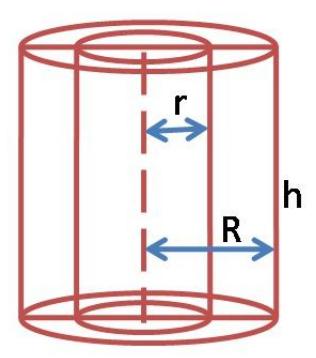
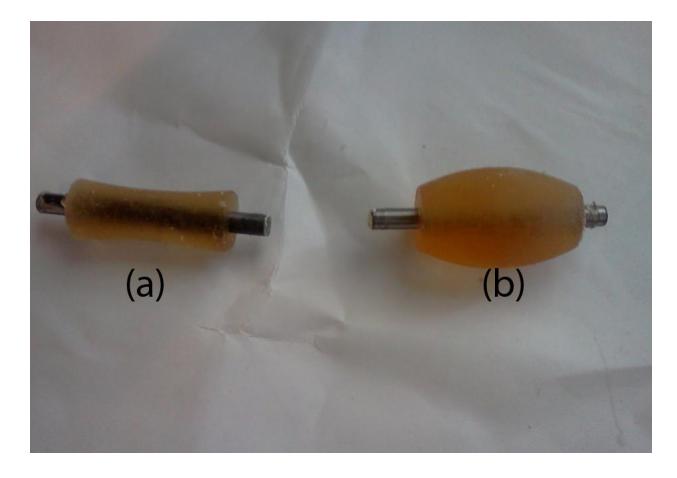
Recent designs of the dribbler involved rethinking the dribbler bar. The robots had a history of difficulty catching the ball, raising questions about the effectiveness of the shape and material of the dribbler. Our solution was to experiment with casting new dribblers made out of urethane on to the metal dowels. The two initial shapes we focused on were concave and convex. The effectiveness of each was a matter of debate among the team, and a mechanical model was needed to ensure the best design would be used.
Models of the finished dribbler were 3D printed so they could be used as a base. First, a silicone mold was cast around the 3D models. After it had set, it was cut open. A new dowel was inserted and the urethane was cast in the hollow space that was left. So far, two series of tests comprising three total dribblers have been done, and the results are highly encouraging. Images of a concave and convex dribbler are included in Figures 1 and 2.
Firstly, bubbling within the urethane has not been an issue, since the small size of the finished pieces mean that vacuum degassing is not required. Secondly, all of the castings were set without any problems with the urethane dribbler releasing from the silicone mold. Thirdly and most importantly, our fears about the urethane having a weak bond with the dowel were not realized. While we need to wait for a full mechanical model to do complete analysis, we ran preliminary tests by attaching the finished dribblers to a drill and running it against a firm surface. The results show that the dribbler will physically fall apart before external forces cause the urethane to slip around the dowel. Since it is unlikely that the dribbler will be pushed to this extreme during competition, it was determined that the connection was strong enough for normal use.
Additional tests with a drill in comparing the two shapes show the concave design takes a lead in ability to control the ball. Fortunately, the convenience of this method of design is that it is easy to make changes to the basic shape of the dribbler. Many types of convex and concave models, as well as almost any design, can be made following the same basic method.
Mechanical Redesign
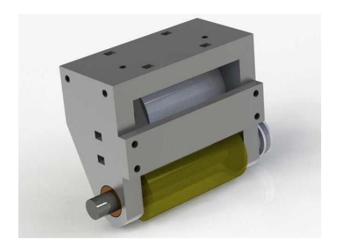
This year also saw changes to the motor and the set-up holding the dribbler. One of the key motivations behind this redesign was to free up space, since the current right-angle drive requires a motor that is perpendicular to the dribbler itself and connected by means of a single twisted o-ring. An ideal solution would be to have the motor and dribbler parallel, with the motor above the dribbler, as shown in Figure 3. This would keep the design compact, as well as distant from possible stresses that the unusual right-angle drive might put on the robot.
The motor in the old dribbler design was much too large to fit in this parallel configuration, due to the space constraints created by the wheel mounts on either side of the dribbler. However, we found that we could remove the gearbox and greatly reduce the length of the motor, enabling us to mount the motor parallel to the dribbler bar again.
In addition, the new design of casting on the dribblers would require a change to how the dribbler bar is attached to the robot. In our old design, the foam outer core of the dribbler was attached on a metal sleeve held onto the spinning dowel pin using a setscrew. In order to mount orunmount the dribbler bar from the rest of the dribbler, we could simply loosen the setscrew, remove the inner dowel, then take out the sleeve and padding. Therefore, the old dribbler mount was machined out of a single piece of metal. However, with our new casting process, the padding on the dribbler bar cannot be separated from the dowel pin itself. Therefore, we had to modify the dribbler mount.
To accommodate these changes, we came up with a modular two-bolt design with removable side plates. We have tried a similar design several iterations in the past but abandoned it due to alignment issues, since any misalignment of the two side plates would negatively affect the smooth spinning of the dribbler. To address this, we have made the side plates thicker to allow the mounting of a front bracing bar to maintain good alignment.
Earlier designs of the motor and surroundings included a layer of some viscoelastic material above the motor to help absorb energy from the incoming ball. However, the success of the cast-on dribbler in catching the ball by itself might make this unnecessary. Current items of action include research for a motor that has the right amount of power and fits within the dimension allotted for it, while being affordable. Once the design has been finalized, the redesign will be complete.
Internally Geared Drive Train
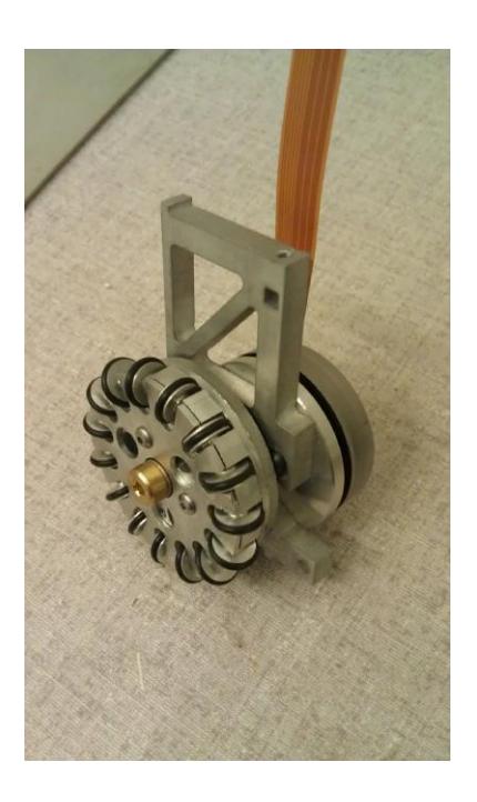
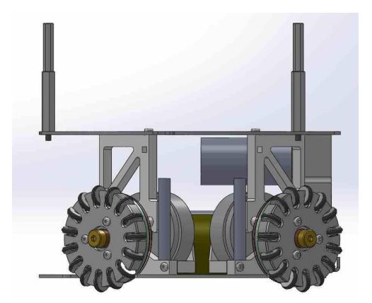
This year the team devoted significant resources to developing a new drivetrain which uses an internal gear rather than spur gears. There were two motivating factors for this:
- A desire to lower the center of mass
- A desire to increase the amount of space available in the robots.
Previously we have observed that our robots frequently tipped over while accelerating quickly and this has limited our ability to accelerate and maneuver. To overcome this limitation, we decided that lowering each robots center of mass would be a central mechanical goal for this season. The motors constitute a significant percentage of the robots weight, and in the current design are mounted high up in the robot. By lowering the height of the motors, we can lower the center of mass and substantially improve our robots maneuvering ability.
The new internally geared design required tighter tolerances and careful design to ensure that components would not interfere with one another and that the design would be assemble and manufacturable. The benefit of the additional complexity is that we would achieve the two design objectives outlined above. The additional space could be used for a variety of future improvements.
Suggestions have already included a modified kicker, a chipper and a further redesigned dribbler. The new drivetrain design interferes with space currently allocated for the batteries, so new batteries or a modification to the design is needed. The mechanical and electrical subteams are currently collaborating in specifying new battery packs.
Redesign of Omni-wheels
The current omni-wheel design has had for us several major problems:
- The rubber O-rings are constantly being shed. Replacing these O-rings is labor-intensive and inconvenient, especially during a match
- Losing roller O-rings also has the unfortunate side effect that the wheels with fewer O-rings have less traction, leading to control issues.
- Picking up green fuzz. We believe that the relatively sharp edges on the current roller design is cutting into the carpet and picking up the fuzz.
- Prototyping any variation of the the omniwheel and omniwheel rollers is extremely labor intensive due to the number of rollers required, the tight tolerances, and the nature of the design.
To solve this problem we are in the process of developing a new omni wheel design which uses purchased single-piece rollers with a hard plastic core and a soft, tractive outer surface. The two plastics are strongly bonded together, so the roller cannot shed the tractive surface. The rollers do not have any sharp edges, they are smoothly contoured. We will be prototyping this design this spring but we do not expect to be able to field it at the international competition this year.
Electrical
Each robot contains a set of 7 printed circuit boards: 4 to control wheel movement, 1 to control kicking, 1 for the power electronics of kicking, and 1 motherboard to act as an interface to hardware. This modularity allows us to easily swap out broken boards when parts are broken.
Break Beam: Addressing False Signals
The robots have break beam sensors in front of the kicker so that we know if a ball is in position to kick. There is an infrared transmitter and an infrared receiver on opposite sides of the kicking area. The break beam sensors were often issued false positives and false negatives. In past years, we attributed this to low quality sensors and dirt buildup on the sensor, so we changed to a TSOP362 series emitter and receiver. Despite this, we continued to get false signals.
To reduce the amount of false singals from the break beam sensors, we had to fix several issues. One issue was that, after running for a certain amount of time, the sensors stopped working when the IR sensor adjusted to the beacon. The receiver does this automatically to filter out ambient light. To prevent the sensor from adjusting, the transmitter must be pulsed with certain specifications. We had to adjust the amount of time the beacon was pulsed to ensure functionality.
Another issue was that the receiver would only sense the beam for approximately 10-20 seconds after the transmitter pulsed. To fix this, we checked the beam value over a period of time instead of just using one sample. We also found that sometimes, the break beam sensor would not register as broken even when there was a ball, especially after the amount of time the beacon was turned on was adjusted. Even if the beam was completely blocked, it would not consider the beam broken. We hypothesized that the light was getting reflected around the barrier. When we decreased the intensity of the beacon by increasing the series resistor to 50 kOhm, the problem was fixed, supporting our hypothesis.
After making these changes, the break beam sensors worked as expected. They no longer have false triggers or fail to trigger when they should.
Dribbler
Each of our robots has a dribbler above the kicker. The dribbler is run by a motor that is controlled by the microcontroller through a MOSfet. So far, the dribbler has not been running, due to several different problems. One problem is that the microcontroller is outputting an on or off signal rather than the PWM signal we need to control the speed of the motor. In addition, looking at the voltage across the motor reveals that the voltage is spiking at 50V due to inductive effects. Another problem is that the motor being used is designed to run at 24 volts, but our robot is only capable of running it at 12.
To fix these problems, we have made several changes. After looking at the documentation for the microcontroller, we found that we were not correctly setting the PWMCON register. Setting this register enables PWM on the output pin. To control the voltage spike, we connected a diode across the terminals of the motor. This prevents the motor from behaving like a LRC circuit. We found that these changes allowed the motor to run even though it is only receiving half of its preferred voltage. In future dribbler iterations, we plan to use a 12V motor.
We may also switch to a different, a longer lasting battery, such as the Tenergy 11.1 V 5000mAh 25C LIPO battery pack. Current robot geometry will not fit this battery, but following the installation of our new drive trains, this may be possible.
Software
We have not added many new software changes. Below is a summary of our recent major changes.
Synchronized Actions
One of our test strategies relies heavily on synchronized robot actions for offense. We use two simple primitives passing and deflection shots on target. Of these, deflections shots are the simpler primitive a friendly robot positions itself near the enemy goal, and the robot with ball possession shoots directly in its direction, at an angle such that scoring is most likely after a deflection from the stationary robot. We carefully characterized deflection angles from our robots, which resulted in several mechanical improvements to strengthen the shields for more predictable performance. Even after this, deflection success rates in our system are still too low to be used regularly in situations, other than the most desperate. Passes require a higher level of synchronization the receiving robot has to be not only positioned, but also oriented correctly to receive the pass. We introduced such synchronization to a test strategy and tested it extensively in simulation. Because controlling kick strengths on our robots was not precise enough, we were not yet able to experiment with passes in the real world and fit our simulator models accordingly.
Zone-based Strategy
We have also experimented with a different robot allocation in terms of strategy. Instead of explicitly assigning robots to offense or defense, we tried assigning different zones to robots and allowing them to switch between defense and offense. The three zones center, left and right were inspired by actual soccer. We have experimented with different algorithms for switching a robot between defense and offense in this case. Most of them were based on ball position and possession by our team / the enemy. However, such heuristics did not prove useful both in simulation and real play because of the delay between switching from offense to defense, which often left our goal not well-protected. We are looking into ways to improve those heuristics that would allow us to not dismiss such a zone-based strategy.
Motion Planning
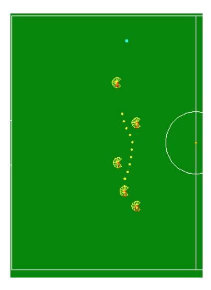
For motion planning, the primary contribution was an RRT (Rapidly-exploring Random Tree) planner [1]. In previous years, we had made a few other attempts at implementing an RRT-based motion planner, but none of them were fast or robust enough to replace a simple TangentBug implementation, which we implemented before. The current iteration has passed our robustness criteria and is currently our default motion planner. The main change we introduced in the current iteration was to model the physical limitations of the robot when trying to come up with a path to follow. We introduced a simple model of maximum velocity and acceleration that was tuned to the physical realities of our robots.We use that model at every RRT expansion step and only expand towards a point if we believe the robot can follow the resulting path. This eliminates path jaggedness to an extent that there is no need for a later path smoothing step. We also bias path expansion towards the direction of the robot's velocity to add further hysteresis and decrease rapid direction switching.
Furthermore, in the implementation of our new motion planner, we made a few key observations that allowed us to create a computationally tractable algorithm:
• On the field, there are usually only a few obstacles immediately in the way (0,1, or 2). • Everything is moving, so planning around distant obstacles is not useful. • RRTs give different answers of varying quality each time they are run.
Based on these observations, we (1) always check direct paths before doing RRT expansion; (2) cut off path planning once expansion reaches a certain predefined radius; (3) run the algorithm multiple times at each time step and choose the best one based on a simple distance heuristic. Furthermore, in terms of RRT implementation, we use recursive k-d trees that partition the 2D space in hierarchical chunks, allowing us to reduce the computational intensity of collision checking.
References
- A. Yershova, S. M. LaValle. Improving motion planning algorithms by efficient nearest-neighbor searching. IEEE Transactions on Robotics, 23(1): 151-157, February 2007
- RFC Cambridge. RoboCup Team Description Paper. 2012
- RFC Cambridge. RoboCup Team Description Paper. 2011
- RFC Cambridge. RoboCup Team Description Paper. 2010