RoboDragons 2013 Extended Team Description
Kotaro Yasui, Yuji Nunome, Hiroaki Sasai, Shinya Matsuoka, Yusuke Adachi, Masahide Ito, Kunikazu Kobayashi, Kazuhito Murakami, Tadashi Naruse
Aichi Prefectural University, Nagakute city, Aichi, 480-1198 JAPAN
Abstract We developed a new robot, Robo-e2012, in 2012. This paper describes the configuration of the robot. The features of the new robot are,
- use of 50 watts brushless motors for driving omni-wheels,
- improvement of maximal velocity,
- new voltage booster circuit which is so compact than the previous ones, which contributes to lower the gravity center of the robot,
- use of wireless LAN,
- improved chip kicker,
- simple proximity sensor.
This paper also describes a summary of our software system and an improvement of the deployment algorithms of the defense robots with experimental results.
1 Introduction
Recent robots in the small size robot league (SSL) are fast, powerful and wellcontrolled thanks to the continuous development of the teams participated in the SSL and the technological development of the parts used in the robots.
Being inspired by the aggressive teams of the SSL, we developed a new robot in 2012. The ability of the robot is mainly determined by the power of motors build in the 18 cm diameter and 15 cm height cylinder, from the point of view of hardware, so that we decided to use a 50 watts DC brushless motor for driving an omni-wheel.
Other features of the new robot are an improved chip kicker, a simple proximity sensor, wireless LAN for communication between robots and the host computer system, and a compact boost converter. These are described in detail in the following sections.
Software development is crucial for the performance of the robot system. Though we use almost the same software as the 2012 system which we described in the 2012 RoboDragons TDP[1], we improved deployment algorithms of defense robots. We describe, in this TDP, the algorithms and experimental results to show how the algorithms work.
2 Robot Hardware
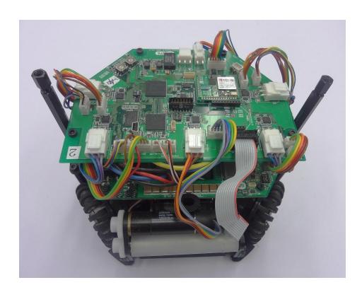
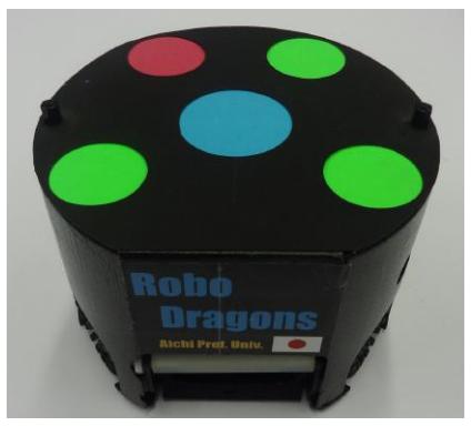
We show pictures of our new robot which we developed in 2012. Figure 1 shows the robot with/without cover. The height of the robot is 12.5 cm, which the gravity center is slightly lower than the previous one (14.5 cm). The diameter of the bottom is 17.8 cm and the weight is 2.3 kg. The maximum percentage of the ball coverage is about 18 %.
2.1 Components of the robot
In this section, we briefly describe the building blocks of the robot. They are summarized in figure 1.
Control unit Figure 2 shows the picture of CPU board of the robot and figure 3 shows the layout of the board. The control unit consists of CPU, FPGA, motion sensor, infrared sensor for ball detection and motor control circuits. The blank part of the board in Fig. 3 is mainly an area for connectors. The operating system used is the TOPPERS[2] (Toyohashi OPen Platform for Embedded Real-time Systems), which is developed in Toyohashi University of Technology based on the ITRON[3] specifications and aimed to develop base software for use in embedded systems.
The robot control program is written in the language C.
Boost Converter Figure 4 is a boost converter board (and condensers). The boost converter is redesigned and implemented in a flat board shown in Fig. 4. It makes the height of the robot lower than the previous one.
Dribble device Figure 5 shows a dribble device. The dribble roller (white) is directly driven by the motor (black) through the gears. The photo diode and LED sensor pair is attached to the black frames (though not seen clearly). The silver (short) shafts in the frames are stoppers that stop the chip kicker not to move further up and let the ball go upward 45 degree direction.
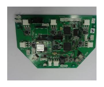
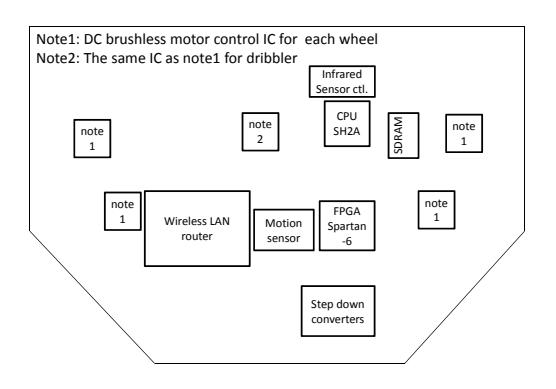
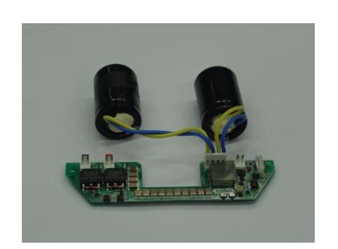
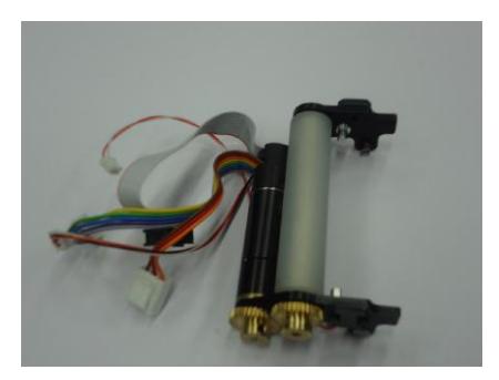
Table 1. Summary of the robot developed in 2012
| Device | Description |
|---|---|
| Control Unit | CPU: SH2A processor (Renesas Electronics Corporation) |
| operated with 196 MHz clock. Peripheral circuits (except | |
| analog circuits) are almost in the Xilinx's Sparta-6 FPGA. | |
| Boost Converter Convert from 18.5V DC to 150V ∼ 200V DC. | |
| Condenser has a capacity of 4400 µF. | |
| Charging time is about 2 sec (when output voltage is 200V). | |
| Motor | Maxon "EC 45 flat 50 W". |
| Gear reduction ratio between motor and omni-wheel is 21:64. | |
| Wheel | 4 omni-wheels, each has 20 small tires in circumference. |
| Diameter: omni-wheel 55mm, small tire 12.4 mm. | |
| Dribble Device | Dribble roller: 16 mm in diameter and 73 mm in length, made of |
| aluminum shaft with silicon rubber. Motor is Maxon "EC 16 30W". | |
| Ball Sensor | Infra-red light emission diode and photo diode pair. |
| Kicker | Kick bar is made of 7075 aluminum alloy. |
| Solenoid is a coil winding 0.6 mmϕ enameled wire. |
|
| Straight kicker kicks a ball with over 10 m/sec velocity at maximum. | |
| Chip kicker kicks a ball as far as 4 m distance at maximum. | |
| Communication IEEE 802.11g wireless LAN. |
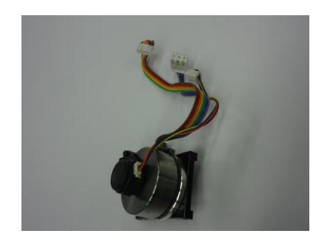
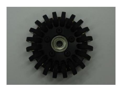
Motors and wheels Figures 6 and 7 show the motor and the omni-wheel. The motor is the Maxon's EC 45 flat 50 watts motor with encoder attached. The omni-wheel has 20 small tires around the large wheel, 5 more small tires than the previous one.
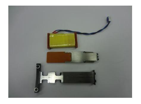
Kicker RoboDragons has 2 kickers, straight and chip kickers, as other teams have. Figure 8 shows solenoids. The upper is a coil which is commonly used in both straight and chip kickers. The middle is a kick bar of the chip kicker and the lower is a bar of the straight kicker.
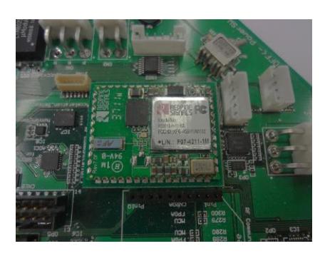
Radio system We have used the radio modem of Futaba Co. in the previous robot because of its stability of radio communication. However, its communication speed was low (19K bps). It is not enough speed for communication of the new robot, so we adopted the wireless LAN. Figure 9 shows the radio device on the robot. The communication speed is 54M bps.
2.2 Robot control program
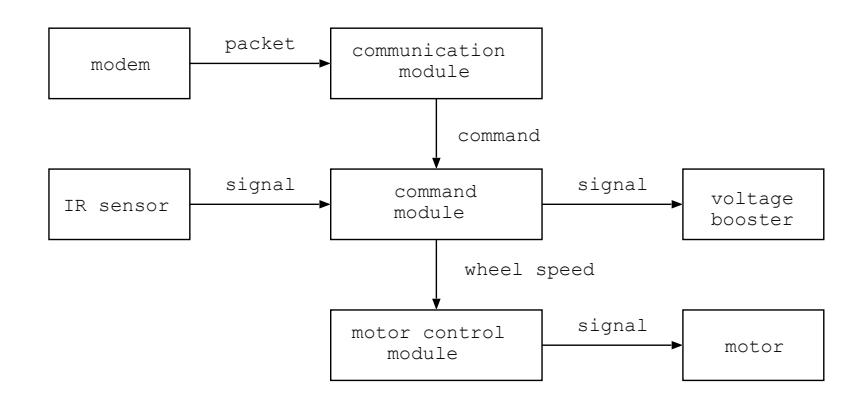
The block diagram of the robot control program is shown in figure 10. In the figure, each box named module is a thread program which run independently and other boxes are hardware which are controlled by modules. Basic control method is the same as the robot developed in 2010[4].
2.3 Configuration of communication packet
Thanks to the fast communication ability of the radio system, we redefined the communication packet configuration. The packet consists of 20-byte header, 43 byte packet body and 2-byte footer. The packet body consists of 7-byte command for each robot and 1-byte common command for all robots.
The 7-byte command is shown in figure 11. Basic idea of the command is that we give the moving vector and the angular velocity of the robot. In the 6th and 7th bytes, we give the kick command. "gggg" field selects the kicker (straight/chip) and the kicking mean (normal/forced). The normal means to kick when the ball sensor detects the ball while the forced means to kick right after the command is issued.
The 1-byte command for all robots is mainly used for debug purpose.
Fig. 11. Command for each robot
| Config. | Description | |
|---|---|---|
| 1st byte | aaaabbbb aaaa: Robot ID, bbbb: Upper 4 bits of robot velocity | |
| 2nd byte bbbbbbbb bbbbbbbb: Lower 8 bits of robot velocity, 0 ∼ 4095 (mm/s) | ||
| 3rd byte cccccccc cccccccc: Upper 8 bit of moving direction, | ||
| Resolution is 2π/512 radian | ||
| 4th byte 000cdeee c: LSB of moving direction. d: Rotation direction, 0:cw, 1:ccw | ||
| eee: Upper 3 bits of angular velocity | ||
| 5th byte eeeeeeee eeeeeeee: Lower 8 bits of angular velocity, | ||
| 0 ∼ 2047 (deg/sec) | ||
| 6th byte ffffffff ffffffff: Kick force, 256 levels | ||
| 7th byte gggghhhh gggg: Normal/Forced kick; 0001: Normal main, | ||
| 0011: Normal chip, 0101: Forced main, 0111: Forced chip, | ||
| hhhh: Dribble velocity, 8 levels | ||
| including rotation direction (cw, ccw) |
3.1 Overview of the software system
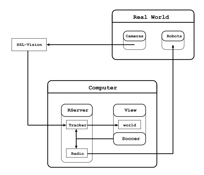
In this section, we show how our software system in host computer is composed and relates to the information from real world. The overview of our software system is shown in figure12.
The host computer is a commercial one. CPU is Intel Core 2 Duo P8400 and main memory is 2GB. OS is Ubuntu 11.04/Linux. Three main modules are running, each of which is composed as follows.
- (1) The Rserver module receives SSL-Vision data and uses tracker sub-module to predict the ball and robot states by Kalman Filter. The information is preserved to world storage, which is shared by other modules. To send a command to each robot, a radio sub-module is used.
- (2) The View module is used to see the simulated image of real world so that users are easy to understand the situation. To do so, users set the numbers of robots and teammate color.
- (3) The Soccer module is used to make an action command for each robot. By using the information of real world, this module chooses the best strategy, gives a role to each robot, and decides a route for each robot.
3.2 Improvement of defense strategy
In this section, we describe the improved defense strategy. See literatures [1] and [4] for our basic defense strategy.
We usually employ 1 - 3 robots, including goalie, for the defense in in-play. This year, we have improved the positioning algorithm of the defense robots.
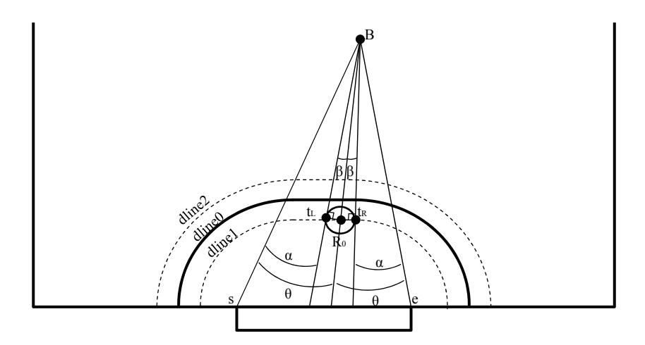
Algorithm 1. (Defense by goalie only) See figure 13. In this case, we think the best position of the goalie is the point on the line (dline1) along the boundary of the defense area (dline0) and the cross point of the dline1 and the bisector of the angle ∠ sBe, where s and e are the edges of the goal mouth and B is a ball.
4 Experiments
To show how the algorithms work we have done the numerical experiments.
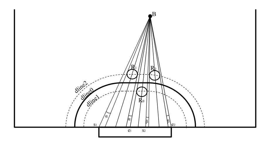
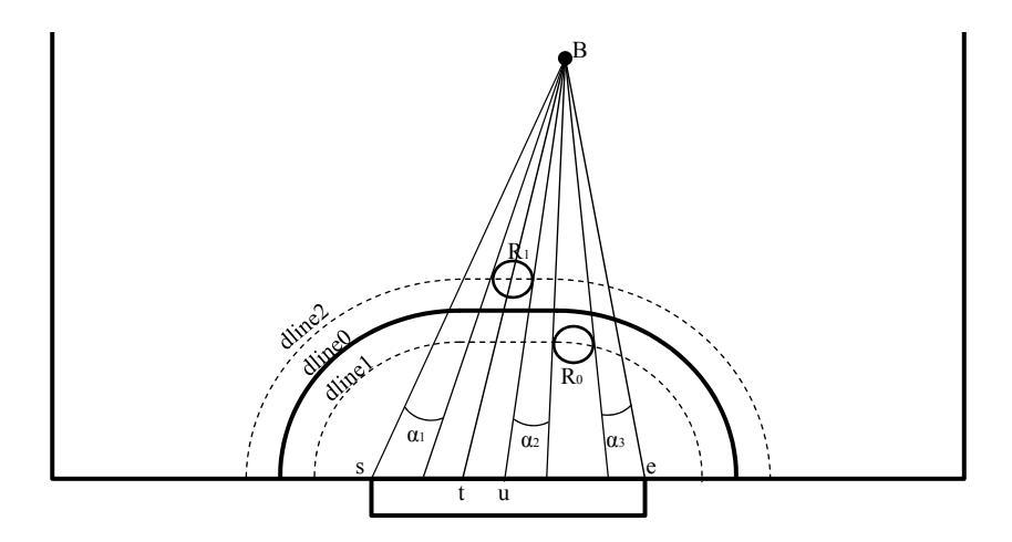
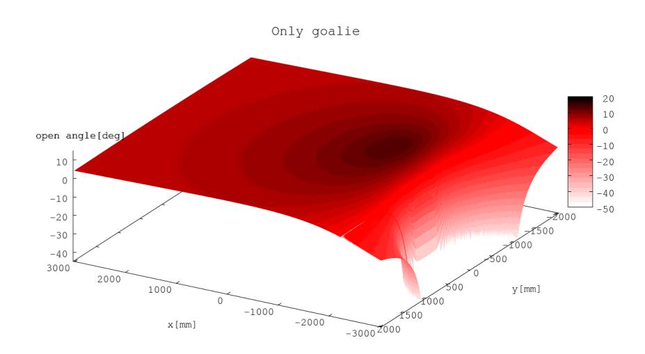
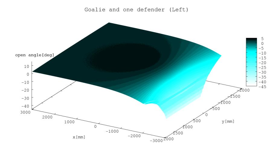
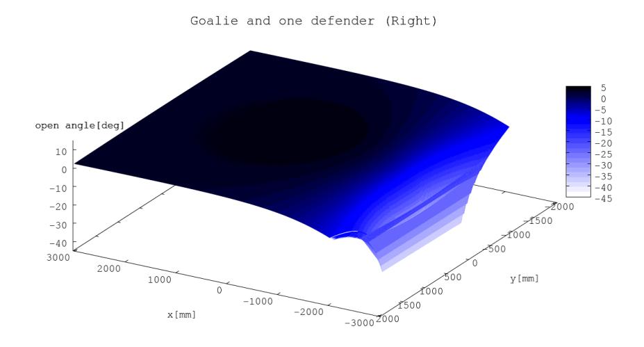
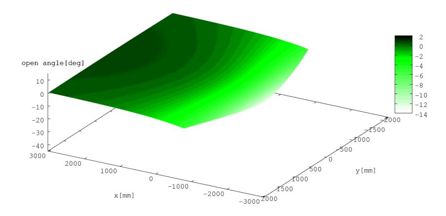
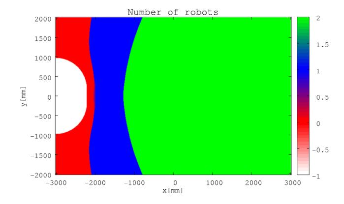
[Numerical experiments] Draw a mesh on the field of size 6050 mm × 4050 mm, one line per 10 mm. For each grid point, put a ball and compute the open angles by algorithms 1, 2 and 3, respectively. That is, for algorithm 1, compute aw = 2α in Fig. 13, for algorithm 2, compute aw = 2α + 2β in Fig. 14, and for algorithm 3, compute aw = α¹ + α² + α³ in Fig. 15. Figures 16, 17, 18 and 19 show the results of aw, where, in case of aw < 0, we think it means the affordance of defense. Grid points in the teammate's defense area are excluded because the algorithms don't work for these points.

5 Conclusion
In this paper, we described the hardware of the new robot and the improved deployment algorithms of the defense robots. The wheels of the new robot are driven by the 50 watt motors so that faster moving can be possible. In the software, we improved the positioning algorithm of the defense robots. We realized the equi-angle deployment algorithm which is expected to minimize the goal probability. We showed the deployment algorithms for robots between 1 - 3 and also showed the experimental results.
References
- Kotaro Yasui, Taro Inagaki, Hajime Sawaguchi, Yuji Nunome, Hiroaki Sasai, Yuki Tsunoda, Shinya Matsuoka, Naoto Kawajiri, Togo Sato, Kazuhito Murakami and Tadashi Naruse "RoboDragons 2012 Team Description", RoboCup 2012 symposium CDROM, 2012
- http://www.toppers.jp/en/index.html
- http://en.wikipedia.org/wiki/TRON project and http://en.wikipedia.org/wiki/ITRON
- Akeru Ishikawa, Takashi Sakai, Jousuke Nagai, Taro Inagaki, Hajime Sawaguchi, Yuji Nunome, Kazuhito Murakami and Tadashi Naruse "RoboDragons 2010 Team Description", RoboCup 2010 symposium CDROM, 2010