RoboFEI 2013 Team Description Paper
Eduardo M. Nottolini, Vitor Hugo M. Beck, Felipe Fill Cardoso, Fernando Rodrigues Jr., Erivelton G. dos Santos, Feliphe G. Galiza, Victor Torres, Danilo Pucci, Victor Amaral, Pedro Tendolin, Milton Cortez, Jos´e Angelo Gurzoni Jr., Reinaldo A. C. Bianchi, Flavio Tonidandel
Robotics and Artificial Intelligence Laboratory Centro Universit´ario da FEI, S˜ao Bernardo do Campo, Brazil
Abstract This paper presents the description of the RoboFEI Small Size League team as it stands for the RoboCup 2013 in Eindhoven. The paper contains descriptions of the mechanical, electrical and software modules, designed to enable the robots to achieve playing soccer capabilities in the dynamic environment of the RoboCup Small Size League.
Introduction
For RoboCup 2013, the RoboFEI team intends to use basically the the same electronic project that has been used last three years, with some modifications. The Mechanical design received minor changes to improve the dribbling system.
The strategy software is undergoing of refactoring. After few years of development was noted that the code became difficult to upkeep and presenting an underperfoming, then we choose the refactoring process. At the end of the process is expected that the development became easier, faster and efficient.
This paper describes the current hardware, the software modules which compose the strategy system of the team, including world model, agent modules, and others that will be used in RoboCup Eindhoven.
Electronic Design
The electronic design has been used and refined for three years, for this year were made few modifications, we believe that at this point it reached the desired level of development.
RoboFEI electronics consist of two boards: the Main board, responsible for all embedded computation and robot's motion control, and the Kicker board, that commands the kicking devices and its associated power electronics. These two boards are described in details in this section.
Main Board
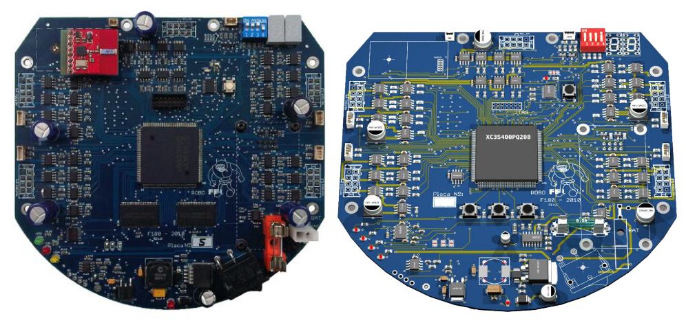
The main board(Fig. 1(a)) has a Xilinx Spartan 3 FPGA (XC3S400) responsible for performing all the logic and control functions. Embedded into this FPGA are a soft-core microcontroller IP, the Microblaze, which has just been updated to version 8.1 this year, five brushless motor controllers, sensor control modules and the kicker board command. The integration of all the functions, including the microcontroller, in the same IC eliminates the difficulties related to component interconnection and avoids the maintenance of multiple firmwares, while at same time considerably reducing the number of components on the board. The Xilinx Spartan 3, with its Microblaze soft-core operating at 50 MHz, provides fast computation, because of its integrated hardware FPU (floating-point arithmetic unit). The embedded firmware is loaded in a 4M words PROM memory connected to the FPGA.
The five brushless motor drivers are designed with the IRF7389 N-P complementary channel MOSFETs, an feature Allegro ACS712 current sensors. The reading of the ACS712 is made by a AD7928 Analog-to-Digital IC. The power to the main board and motors is provided by one LiPo battery of 3-cells (11.1V ) and 2200 mAh capacity.
The radio system is based on the Nordic nRF24L01+ transceiver. These transceivers operate on the frequency range between 2.4 and 2.5GHz and have data transmission rates of up to 2M bps. With this bandwidth,telemetry data can be obtained from the robot during the matches. Each robot carries one transceiver, connected via SPI bus to the microcontroller, which is used to both send and receive data. The robot transceiver communicates to the radio station connected to the strategy computer. The radio station contains two nRF24L01+ modules operating on independents channels, one to receive and one to transmit. The radio station has an ARM7 CPU, responsible for the transceivers operation, data queuing, data integrity validation and interfacing with the USB port. The board also features a RF amplifier based on the MGA-85563 IC, used to boost the TX signal to 15dBm, ensuring enough power to reach the robots reliably even at larger distances.
Although RoboFEI's Main board is a fully functional and mature hardware design, its life-cycle is still closely monitored. This year, a new revision of the board, shown in Fig. 1(b), has been developed. The RAM memory, which was not being used to load the firmware, has been replaced by a SPI interface Flash memory, to store the robot's sensors and status measurement data. A motor-enable circuit using an IRF9310 MOSFET was also added, to protect the brushless controller transistors from transient surges during power on and off, as well as an auto power-off circuit, that will avoid damage to both the battery and electronics circuitry in case the robot's battery gets exhausted (i.e. if it's forgotten powered on).
Kicker Board
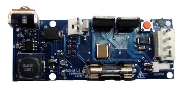
The kicker board, shown in Fig. 2.2, is responsible for controlling both the shooting and chip kick devices. uses a boost circuit designed with the MC34063 IC. This IC produces a 100 KHz PWM signal to charge two 2700 µF capacitors up to 200V . This IC controls the whole circuit, sparing the main-board's CPU from the need to generate the PWM signal and monitor the capacitor's charge. The board features two IRFSL4127 MOSFET transistors, responsible for activating the shooting and chip solenoids. Its power supply is independent, fed by a 3 cell (11.1V ), 800mAh, LiPo battery, and all the connections to the main board are opto-coupled, to avoid spikes and eventual damage to sensitive electronic circuitry.
Mechanical Design
In compliance with the SSL rules, the height of the robot is 148 mm, the maximum percentage of ball coverage is 15% and the maximum projection of the robot on the ground is 146 mm.
The current mechanical design, as the previous ones, is essentially made of aluminum alloys of the 6000 and 7000 series, due to their good hardness/weight relation. Exception are the more stressed parts, such as wheel axes and the small rollers of the omnidirectional wheel, that are made with stainless steel. Parts that are required to be light-weighted and provide electrical isolation are made of Nylon or Celeron.
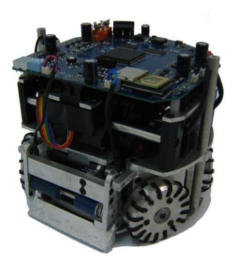
The mechanical design is undergoing minor changes in the dribbler and kick devices as well as the robot's distance from the ground. A general view of the robot can be seen on Fig. 3.
Dribbler Device
The dribbler device uses a Maxon EC-Max 22 25W motor, which allows the device to have greater angular speed while maintaining the required torque.
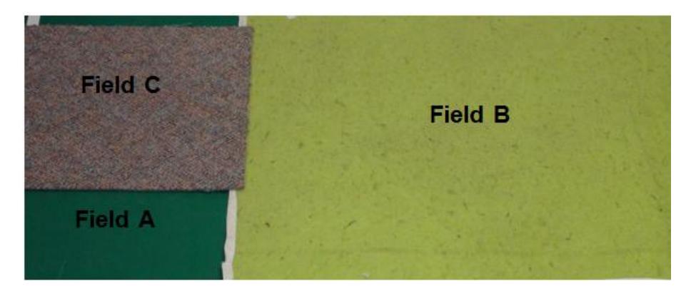
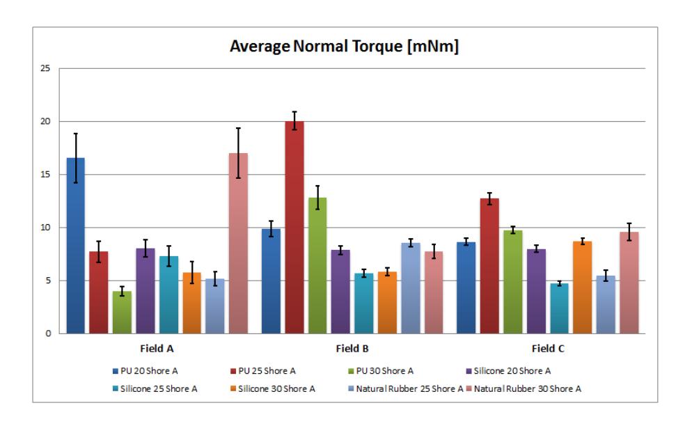
To improve the ball adherence to the dribbler device, we resorted to dynamic simulation, seeking to find optimized dribbler device parameters that could then be tested in the real robots. The dynamic simulations indicated that increasing the contact angle between the roller bar and the ball, i.e. lifting the roller, would also increase the torque applied on the ball, as well as a relatively large variation due to the dribbler bar material. It is also a known fact that the carpet type has an important role in the performance of the device. Based on that, three carpet types and eight different polymeric materials were used in an empirical analysis, with the goal to find the best material to be used in the rolling bar. Fig. 4 shows the carpet types used in the experiments.
Kick Device
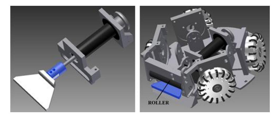
For this year, was made a new geometry in the kick device because with the old geometry is not possible to use a continuous rubber in the roller. The dimensioning of the kick was made using Stress Analysis, respecting the conditions of stiffness, ensuring the integrity and functionality of the structure. The new geometry of the kick and your position in the assembly can be seen on Fig. 6.
Distance between the robot and ground
In the past competitions we had problems with the type of carpet used in the fields of the RoboCup because the distance between the bottom of the robots and the ground was very small, and how the carpet was too thick if compared to the carpet utilized in our laboratory, the robots sank a few millimeters. This resulted in problems of locomotion, the robots did not respect the trajectories sent by the strategy because they skidded. The team found this problem in the last two RoboCup and were made fast solutions for put the robots in playing conditions, now the bottom of the robots that going to the RoboCup 2013 are with a distance of 10 mm with respect to ground.
Changes in the distance between the bottom of the robots and the ground over the years.
| Competition | Distance from ground to robot's bottom |
|---|---|
| RoboCup 2011 | 6 mm |
| RoboCup 2012 | 8 mm |
| RoboCup 2013 | 10 mm |
Strategy System
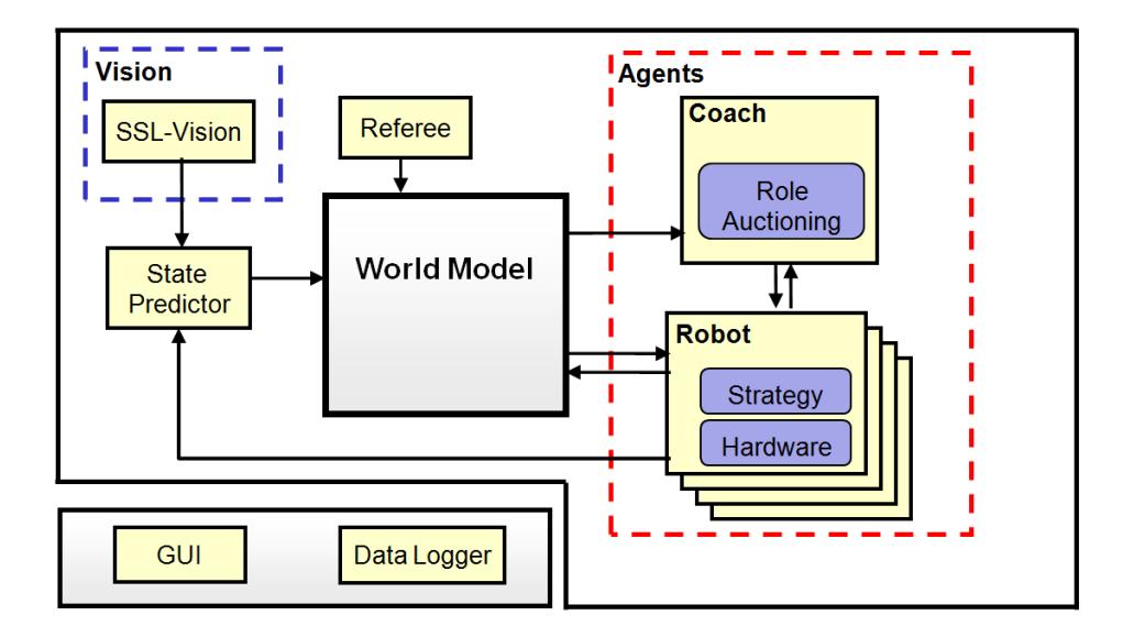
For this year we will use the same software structure(Fig. 7) used last year that basically consist of some world modeling blocks, logically independent agent modules, and visualization and data logging blocks. For this season the work is concentrated at a refactoring process that the software is undergoing.
World Modeling
The world model is updated by the state predictor module. This module receives vision data from the SSL-Vision and motion command data from the agent modules, sent when they command the robots via radio, and performs state predictions, The prediction is to advance the positions sent by the SSL-Vision from their original capture time to the present and then forwarding one strategy cycle in the future, the so called latency of the strategy system. This latency is currently on the order of 80ms.
The prediction algorithms used for ball, robots and adversaries are different.The ball prediction is made by an Extended Kalman filter (EKF) (see [8]), a well known method for position estimation.
The robot's prediction is performed similarly to [1], with multi-layer perceptron neural networks. These networks are trained off-line to learn the robot's motion model, receiving past frames and motion commands as input and a frame n steps in the future as output. Once trained, the networks are used for on-line estimation of the robot's position and rotation.
As for opponent estimation, currently it is done with simple extrapolation of the last velocity data and Gaussian functions.
Agent Modules
Each robot player is an independent module, executing its own instance of one or more strategy submodules and its hardware specific functions (such as motion control and sensing). The current implementation relies basically on a layered strategy architecture and a market based approach for dynamic allocation of functions, both described ahead on this section.
Strategy module
Building multi-agent systems in a layered architecture with different levels of abstraction is a popular approach (see [5], [2] and [3]) well suited as foundation for machine learning algorithms, one of the research goals. For this reason, the strategy module architecture was divided in three abstraction layers.
The lowest layer has the so called Primitives. Primitives are actions that mostly involve directly activating or deactivating a hardware module such as to kick the ball with a given strength, activate the dribbling device, rotate or move to a position.
On top of the primitive layer, is the Skills layer. Skills are also short duration actions but involving use of one or more primitives and additional computation, such as speed estimation, forecasting of objects' positions and measurement of primitive tasks' completion. This layer has a small set of skill functions, yet that represent the basic skills required in a robot soccer game, like shooting the ball to the goal (aiming where to shoot), passing the ball to a teammate, dribbling, defending the goal line or tackling the ball (moving toward the ball and kicking it away).
One example of such skill is the Indirect Free Kick skill, which employs a multi-criteria weighted evaluation to determine the best for the robot to pass the ball to. Grids are constructed in different areas of the field, then the weighted multi-criteria evaluation function is employed to decide which of the grids contains the best candidate position. Once the area is chosen, the function recomputes using a finer grid, to determine the exact position. The objectives evaluated are the Euclidean distance of each position, in relation to both the robot and the ball, the width of the angle a robot in that position would have to to kick to the goal and the distance between the current positions of the teammates receiving the pass and the chosen positions in the grid.
The skills are employed by the Roles layer, which contains different roles, created using combinations of skills and the logic required to coordinate their execution. There are roles called fullback, defender, midfielder, striker, forward and attacker. No particular robot is tied to a given role (except the goalkeeper), and there is no limitation on how many instances of the same role can exist, what allows dynamic selection mechanisms to create role combinations without restrictions.
Work In Progress
After almost four years of development and more than a handful of programmers contributing to the software, a large chunk of code has been written, modified, patched and moved around, what has resulted in loosening of coding standards, few contradictions between designed and implemented models, and even performance degradation. This also led to difficult code to maintain and improve. Therefore, we decided to take a common approach in software development, a sort of refactoring project. While refactoring is defined by the modification of the structure of a code without changing its external behavior [4], our code refactoring both aims at refining the existing software and adding functionality to it, in parallel.
To do so, the refactoring project has been divided in two lines of work: on is focused into the modules that compose the robots' higher level behavior, like the roles, while the other is intended to ensure the designed model matches the implementation and programming paradigms and coding standards are rigorously followed.
A new software version, the "Flying Dutch" release, from the scratch. The functional diagrams were re-created in the new software version, and guidelines for the porting of algorithms, classes and modules have been created. For instance, classes can only be ported from the old version if they passing a thorough functionality review, which includes matching the designed functional diagrams, code clarity, code commenting, standardization and performance checks. Two software engineering books, [6] and [7] have been helping in the task.
Acknowledgments
We would like to thank, in advance, the Small Size League Committee, for the consideration of our material. We would like also to immensely thank the staff of Centro Universit´ario da FEI, for all the help we always received.
References
- Behnke, S., Egorova, A., Gloye, A., Rojas, R., Simon, M.: Predicting away robot control latency. In: Proceedings of 7th RoboCup International Symposium. Springer (2003)
- Bowling, M., Browning, B., Veloso, M.: Plays as effective multiagent plans enabling opponent-adaptive play selection. In: Proceedings of International Conference on Automated Planning and Scheduling (ICAPS'04) (2004)
- Browning, B., Bruce, J., Bowling, M., Veloso, M.: Stp: Skills, tactics and plays for multi-robot control in adversarial environments. In: IEEE Journal of Control and Systems Engineering. vol. 219, pp. 33–52 (2005)
- Fowler, M.: Refactoring: Improving the Design of Existing Code. Addison-Wesley, Boston, MA, USA (1999)
- Mataric, M.J.: Learning in behavior-based multi-robot systems: Policies, models, and other agents. Cognitive Systems Research pp. 81–93 (April 2001)
- McConnell, S.: Code complete. Microsoft Press, 2 edn. (2004)
- Sutter, H., Alexandrescu, A.: C++ Coding Standards: 101 Rules, Guidelines, and Best Practices. C++ in-depth series, Addison-Wesley, Boston, MA (2005)
- Welch, G., Bishop, G.: An introduction to the kalman filter. Tech. Rep. TR 95-041, Department of Computer Science, University of North Carolina (2001), http://www.cs.unc.edu/welch