RoboIME : Team Description Paper for RoboCup 2013
Andre O. P. Barcelos, Diego F. de Almeida, Jan Segre, Luis R. L. Rodrigues, Paulo F. F. Rosa, Stefano H. Rodrigues, Thiago A. N. do Amaral, Vitor H. F. Betio, Vitor L. H. Ferreira, Victor Bramigk
Section of Computer Engineering Instituto Militar de Engenharia (IME)
Abstract This paper describes the electronic, mechanical and software designs developed by RoboIME Team in order to join RoboCup 2013. All designs are in agreement with the rules of Small Size League 2013. This is the second RoboIME participation in a world level RoboCup event, although the team was already challenged third in Brazilian competitions.
1 Introduction
RoboIME is a small-size league soccer robot team from IME, Rio de Janeiro, Brazil. This is only the third time the team is taking part in competitions. The main result was in 2012 when the team achieved second place in Latin American Robotics Competition.
All students that work in this project are members of the Laboratorio de Robotica e Inteligencia Computacional at IME. The previous studies [1][5] provided the basis for the current structure of software and hardware team's. This paper describe the computer, electronic and mechanical design.
2 Software System
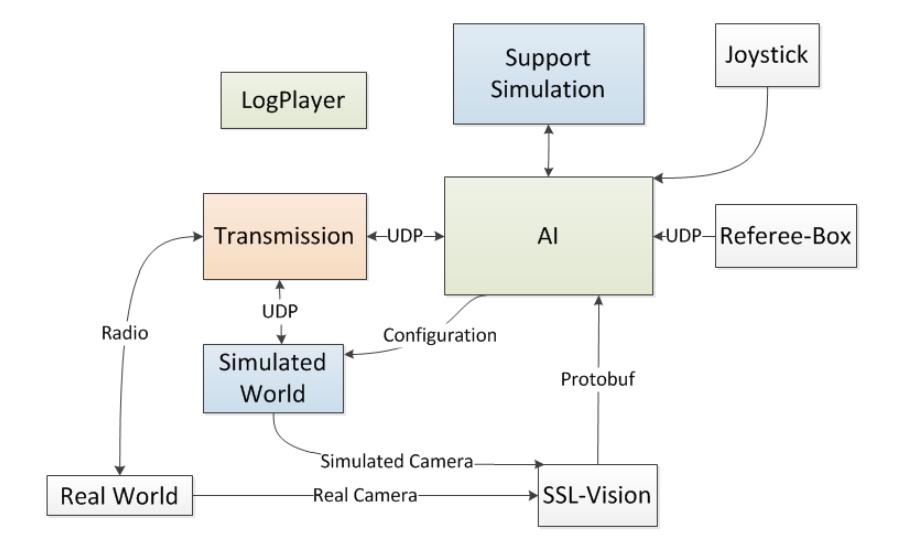
The software system consists basically of five modules: AI, LogPlayer, Simulated World, Support Simulation and Transmission. The modules were implemented using the Microsoft Visual Studio 2010 IDE, that allows a single solution integrated of projects in different programming languages (e.g. CSharp, C++), making the project more flexible for other programmers giving continuity to the implementation.
We chose to adopt the fragmentation of the software project into modules to facilitating the implementation team. A UDP socket interface was adopted for communication between most modules giving independence to them. Some interfaces like between AI Module and Support Simulation Module, that need high performance, don't communicate using the UDP Socket interface. Figure 1 shows the block diagram of the software system.
2.1 AI Module
This is the largest and most complex software module. It is responsible for the following features:
- Collect, interpret and filter data from the Referee-Box, SSL-Vision, Transmission Module (real world or simulated), Support Simulation Module and Joystick;
- Take high level decisions to define the actions that robot should do (i.e., to find the position and orientation that robot has to reached, find the force to kick the ball, find the torque to dribble the ball);
- Use the Support Simulation Module to create a planning;
- Make a short future preview of the world (real or simulated) using data from the sensors (encoder, camera, infra-red);
- Make the configuration of the simulation environment Simulated World (setting bodies existing in the simulation);
- Control position and orientation of the robot defining which speeds the robot actuators (motor, kicker and dribbler) must reach. These speeds will be passed to Transmission Module to be sent to the World (simulated or real);
Among the many reactive behavioural control architectures, we have chosen STP (Skills, Tactics and Plays) architecture [3]. In order to create a plan, we use two algorithms: Minimax [6] and BK-BGT (Behavioural Kinodynamic Balanced Growth Trees) [7]. These algorithms works as Play on the STP architecture.
On the implementation of Minimax, the players agents are based on objective (assessed by an objective function) and the minimax algorithm is used to define which heuristics (Skills, Tactics and Plays) to use. The objective function consider several factors: distance from the ball to the opposing goal, distance from the ball to the goal together, distance from the ball to the opposing players, among others. The two algorithms use the Support Simulation Module to creating a Physics-Based Robot Motion Planning.
Extended Kalman Filter (EKF) [8] is used to offset the effects induced by time latency in that accumulates in vision systems, AI, communication and execution of commands for the robot.
2.2 LogPlayer Module
This module is important to debug the planning algorithms. AI Module creates a log file with all the information necessary to describe the tree planning, so using the LogPlayer Module we can play the log files to visualize all possible solutions present in the tree planning.
2.3 Support Simulation Module
This module is part of F180 environment simulator. It simulates the physics of bodies presented in a match from the Small Size Robot League. Its also so possible to make the control of robot actuators (motor, kicker and dribbler).
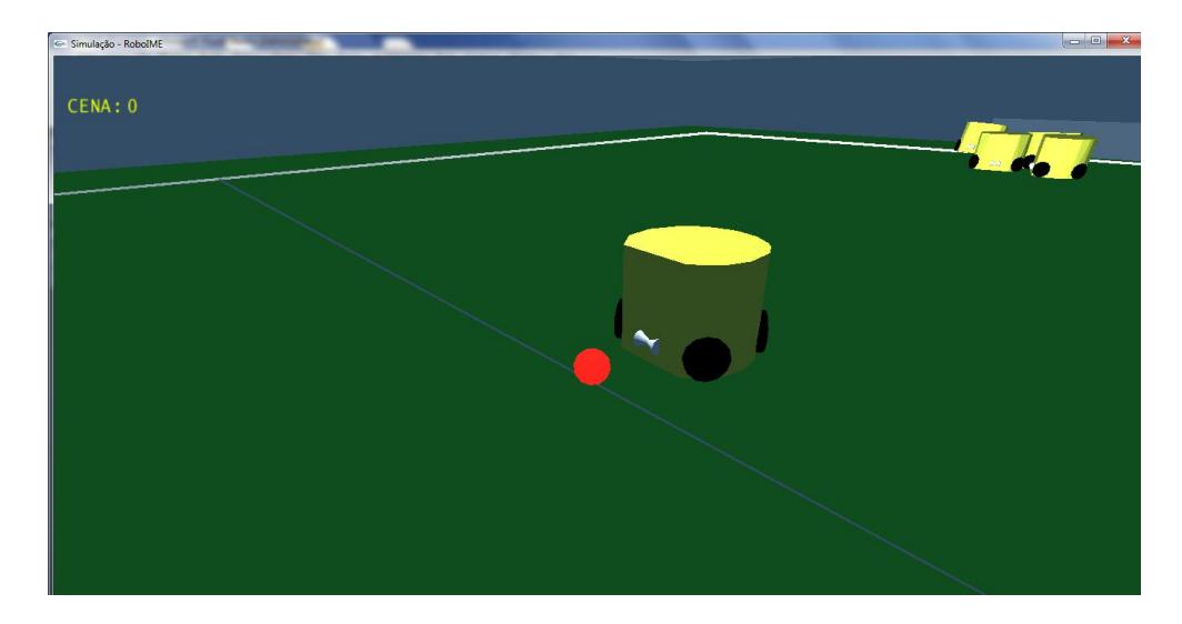
The simulator was developed using the PhysX Engine, that enables high performance processing physics calculations in a GPU. Figure 2 shows the robot in the simulator. This module can provide long-terms predictions, in opposition to the Kalman Filter that provides a short-term prediction.
2.4 Simulated World Module
This module is also part of the simulator designed to F180's environment. But this module replaces the Real World, when it is not convenient to use it. Thus this module receives through UDP sockets the speeds that the actuators of the robot must reach, the simulator has an internal controller to calculate the torque required to be applied to the actuators to achieve the desired speed (like real robot).
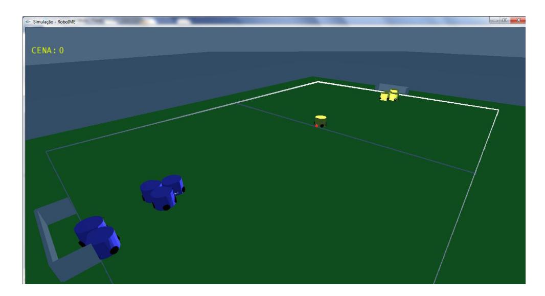
The AI Module can configure the simulation environment of the Simulated World Module just sending an XML file, via UDP Socket, containing information for the construction of bodies in the simulator. This module has two simulated cameras which provide input to SSL-Vision, we use two OpenGL cameras and the images are sent through TCP sockets.
2.5 Transmission Module
This module is responsible for delivering the speed to actuators and receiving status of the robot, such as real velocity of each motor, kick sensor status and power supply status, via radio in Real World or via UDP socket in Simulation World. This module is coded in CSharp language using the interface development Microsoft Visual Studio 2010 IDE.
3 Path Planning
Path planning algorithm is based on the theory of Artificial Potential Field [4], which has as its fundamental principle driving the robot in an artificial force field generated by obstacles and the target. The potential (gradient) should be continuous. The obstacles (other robots) and the target (certain objective local) generating fields of repulsion and attraction, respectively, obtaining a movement by which avoids obstacles and possibly reach your goal.
4 Electronic Project
RoboIME electronics consist of seven boards: (a) the Main board, responsible for communication between the other boards; (b) the Stamp board, responsible for the embedded computation; (c) the Kicker board, responsible for maintaining the high voltage to activate the kick shoot; (d) four motor controller board which are responsible for robot's motion control. These boards are described in details in this section.
4.1 Main Board
The Main Board features a socket to plugin the boards: kick's sensor, dribble's motor, four wheel's motor, four encoders and the power supply. There is a RFM12b SMD embedded which is a wireless transceiver operating in the 434 MHz band, set as up to 115.2 kbps, fully in agreement with with FCC and ETSI regulations.
The communication protocol used between the Stamp Board and the transceiver was Serial Peripheral Interface Bus (SPI), that is a synchronous serial data link standard that operates in full duplex mode.
4.2 Stamp Board
This board is responsible for performing all the logic functions. It is like a brain of the electronic system. There is a embedded micro-controller STM32F103, that has ARM Cortex M3 as main CPU, 512 k RAM memory, working in 72 MHz, that was programmed with C language using the interface development CoIDE.
4.3 Kicker Board
This board is responsible for controlling the kick strength. There is only one kind of kick, the kick shoot. Two capacitors 1000 µF, 250 V are used to raise voltage in a boost circuit. The charge is discharged in a solenoid and depending on the PWM signal the kick device is activated, it is possible to control the kick velocity.
4.4 Motor Controller Board
The idea of the RoboIME electronic is to modularize the electronic project. So, there is controller module board for each wheel's motor. If one of them burns out, it is possible to change quickly. Each board has two TC4427 (MOSFET driver) and two IRF7319 (half H bridge). These ICs create a H-bridge, allowing velocity control in both directions.
5 Mechanical Project
In compliance with the SSL rules, the height of the robot is 148 mm, the maximum percentage of ball coverage is 15% and the maximum projection of the robot on the ground is 175 mm.
With the aid of CAD software (Computer Aided Design) and CAM (Computer Aided Manufacturing) a new robot has been developed. Figure 4 shows mechanical 3D view and real view of the robot. In relation to the shelf that had been used, this allows movement omnidirectional and has a greater torque that couples the fourth motors (one for each wheel) for the movement.
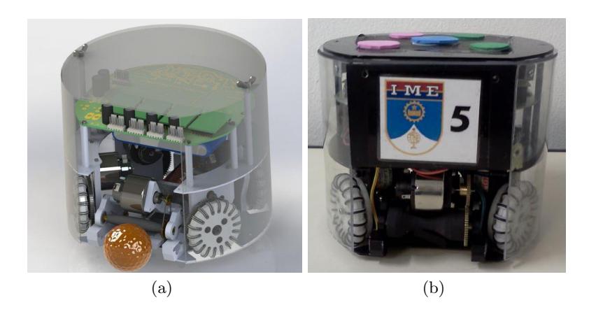
The changes in the original design of the model provides a lower weight to the robot, such as: changing the steel shaft by a shaft of high-strength aluminium wheels and replacement of aluminium by plastic wheels Polytec 1000. This new design also enables more devices to be shipped. It presents a diameter of 175 mm and an upper base with holes which give versatility to the coupling. The fairing of the robot was made from polyvinyl plates.
6 Final Comments
The development of the Robocup 2013 mechanical project was recently concluded, based on the one we created for Brazilian Robotics Competition 2012. The six robots have already been manufactured, with only a few parts still needing rework. Some eletronical prototypes were made, yet stabilizing efforts are still ongoing. The five modules of the AI system have already been implemented but they still need to be brought to perfection.
To the June competition, following goals are being sought: rework the remaining parts on the mechanical project such as making improvements on the coiling of the solenoid coil; stabilize the electronic project, including robot feedback and conclude the implementation of planning algorithms to be used in support decision making.
Acknowledgements
This research was partially supported by Fundacao Carlos Chagas Filho de Amparo a Pesquisa do Estado do Rio de Janeiro -FAPERJ(grant E-26/111.362/2012); Fundacao Ricardo Franco (FRF) and Fabrica de Material de Comunicacao e Eletronica (FMCE/IMBEL). The team also acknowledges the assistance of Mr. Carlos Beckhauser from FMCE.
References
- Alexandre Tadeu Rossini da Silva: Comportamento social cooperativo na realizacao de tarefas em ambientes dinamicos e competitivos. Instituto Militar de Engenharia, Rio de Janeiro (2006)
- Madeira, B. E., de Almeida, D. F., de C. Maia Jr., E., Rodrigues, L. R. L., Rosa, P. F. F., Rodrigues, S. H., and do Amaral, T. A. N.: RoboIME: Team Description Paper for RoboCup 2012.
- B. Browning and J. Bruce and M. Bowling and M. Veloso: STP: Skills, tactics and plays for multi-robot control in adversarial environments Carnegie Mellon University, Pittsburgh, PA (2004)
- Khatib, O.: Real-Time Obstacle Avoidance for Manipulators and Mobile Robots. In International Journal of Robotics Research, vol. 5, no. 1, p. 90-98 (1986)
- Marco Antonio Firmino de Sousa: Uma Plataforma para Cooperacao Autonoma de Multiplos Robos Instituto Militar de Engenharia, Rio de Janeiro (2008)
- Russell, Stuart J.; Norvig, Peter: Artificial Intelligence: A Modern Approach (2nd ed.) Upper Saddle River, New Jersey: Prentice Hall, pp. 163-171 (2003)
- Stefan Zickler: Physics-Based Robot Motion Planning in Dynamic Multi-Body Environments Carnegie Mellon University, Pittsburgh, PA (2010)
- Welch, G. and Bishop, G.: An introduction to the Kalman filter. Technical Report TR 95-041, Department of Computer Science, University of North Carolina (2001)