RoboJackets 2013 Team Description Paper
Nikolaus Mitchell, Hunter Scott, Stoian Borissov, Eric Huang, Ryo Osawa, Matt Barulic
Georgia Institute of Technology - Atlanta, Georgia, USA
Abstract For the 2013 RoboCup SSL season, the Georgia Tech RoboJackets team has developed a new prototype, updated the mechanical designs, improved the electronics, and refactored much of the software that was outlined in the previous year's TDP. Robustness to hardware failure, improved traction and motion control, and overall gameplay has been improved. The current robot eet additionally includes many incremental improvements over the 2012 design to address deciencies in the previous design. This document describes our overall system, with a focus on the improved software system, new electrical design, and mechanical content not present in the 2012 TDP [3].
1 System and Team Overview
We divide the robot system into a three subsystems with a corresponding subteam:
Mechanical designs and builds the physical robot chassis, drive components, kicking/chipping mechanisms, and mounting all of the electrical hardware within the robots. They are also responsible for engineering the placement of all components, both electrical and mechanical, within the robot.
Electrical designs and builds the control circuitry for the robots. This includes the motor driver modules, the kicker solenoid system, and the radio communications modules.
Software handles control of the robots from the main computer, including world modeling, low-level control, and high-level strategy and planning.
While each subteam can work on a particular segment of the project, many zones necessitate signicant collaboration between the subteams, such as accounting for electrical considerations in design of the kicker & chipper systems, or sensor integration relevant to control approaches. There are two main phases of development work: prototype design, and validation testing. In prototype development, the mechanical and electrical teams collaborate to design, build and test the physical components of the system, and undergo design reviews from the rest of the team. Likewise, during validation testing, systems are assessed from a manufacturability and performance stand point both separately and as a fully integrated unit. Once a fully integrated unit is tested, construction on a new eet may begin. This has been the case for the current year with the development of the 2013 prototype. Much of the winter semester was spent on discussing changes to, and the designing of the a new system. While the later spring semester contains the actual testing and machining duties.
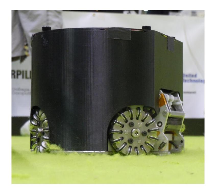
Table 1: Robot Dimensions and Ball Coverage
| Year | Height | Diameter Ball Cover | ||||
|---|---|---|---|---|---|---|
| 2013 136.3 mm 179 mm | 19.5% | |||||
| 2011 136.3 mm 179 mm | 19.5% | |||||
| 2008 147.7 mm 178 mm | 9% |
2.1 Fixes from 2012 Software
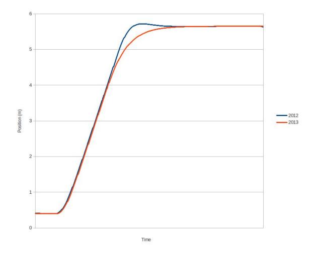
In an eort to improve our ability to adjust motion planning and control algorithms, we have modularized the related code. This allows for quick swapping of dierent planning algorithms and improves the ease with which the code can be maintained. Along with this modularization came an upgrade from our previous PD-controller to a full PID-controller to help compensate for rougher spots of the eld that hinder robot motion. These spots may include ridges and bumps in the eld material. After this change and a further ne tuning of the controller constants, we were able to signicantly reduce the oscillation in robot position generated by our controller.
During the 2012 RoboCup Mexico Competition, the overhead vision system used low-hanging, angled theater lights for illumination. This saturated the infrared spectrum, thus causing ball sensor failures. To x this issue, we have introduced vision based kicking (as a back-up mode). However, vision-based kicking is highly inaccurate due to system latency and because it requires centimeter resolution in vision data in order to determine if the robot is lined up with the ball to kick. Due to this costly fault, we are working to integrate better sensors and mechanical design to avoid such problems in the future.
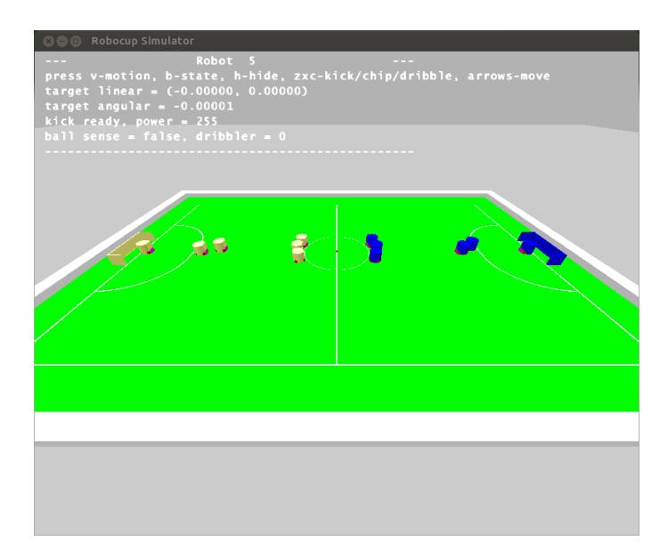
Our RoboCup Simulator has been redesigned to use Bullet Physics Engine instead of Nvidia PhysX. Our new Simulator has several features we proposed in 2011 which we believe will aid in testing the robustness of our Soccer AI (see [2]).
- 3D Simulation: Necessary for testing chip-based plays and for simulating more accurately the dynamics of SSL robots.
- Camera Model: 3D models permits modeling of certain artifacts of real-world cameras such as curved trajectory of chip kicks and ball occlusion during closequarters robot scues.
- Error Simulation: We can use the simulator to mock error conditions, including but not limited to latency, faulty ball sensors or broken kickers.
2.2 Dynamic Passing
In order to be competetive in the current RoboCup SSL environment, it is necessary to perform dynamic passing amongst robots. We define dynamic passing as a pass between two robots in which the receiver lines up with the passed, fast-paced (> 1 m/s) ball and then kicks the ball towards a target. We present our variation of a Bang-Bang control algorithm that solves for a velocity profile to acheive dynamic passing.
Let $P_R(t), V_R(t)$ and $P_B(t), V_B(t)$ be functions representing the velocities of the receiving robot and ball at time t, respectively. Define $T_R, T_B$ to the target robot and ball location for the pass. Let $t_0$ be the time at beginning of the pass and $t_f$ the required time such that $P_R(t_f) = T_R$ and $P_B(t_f) = T_B$ , and $V_R(t_f) = V_B(t_f)$ . Therefore $t_f$ is the time at which we wish to acheive dynamic line-up. At time $t_f$ , the robot will have traveled $d_R = |P_R(t_0) - T_R|$ and the ball will have traveled $d_B = |P_B(t_0) - T_B|$ . Further, we define $V_{max}$ , $A_{max}$ and $D_{max}$ as the maximum allowable robot velocity, acceleration and deceleration.
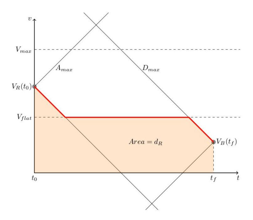
Given the initial velocities $V_R(t_0)$ , $V_B(t_0)$ , distances to travel $d_R$ , $d_B$ , final velocities $V_R(t_f)$ , $V_B(t_f)$ and physical caps $V_{max}$ , $A_{max}$ , $D_{max}$ , we can fully define the control problem. The polygon defined by $(V_R(t_0), V_B(t_f), A_{max}, D_{max}, V_{max})$ represents the space of feasible robot trajectories which take $V_R$ through the velocity $V_B(t_f)$ . To achieve dynamic passing, we must find a trajectory in this space that satisfies $\int_{t_0}^{t_f} V_R(t) dt = d_R$ .
By observation, the maximum and minimum distances traveled by the robot can be acheived by driving the respective path through the extrema of the polygon. Our strategy for generating a velocity profile will be to specify a $V_{flat}$ velocity and drive along the path specified by the intersection of $V_{flat}$ with the polygon (see Fig. 3). Because $\int_{t_0}^{t_f} V_R(t) dt$ is a continuous function of $V_{flat}$ as we vary $V_{flat}$ from polygon top to bottom, it follows from the Intermediate Value Theroem that all feasible distances can be acheived with this strategy. Thus, a velocity profile for dynamic passing can be calculated using basic geometric principles and bisection search over $V_{flat}$ .
3 Mechanical
For the 2012-2013 season the mechanical team of the RoboJackets focused on designing and building a new prototype model, and improving the robustness of previous years drive modules. In addition to these major changes the mechanical team introduced minor changes to older robots to accommodate new electronic improvements such as the laser diode implementation.
3.1 Prototype 2013
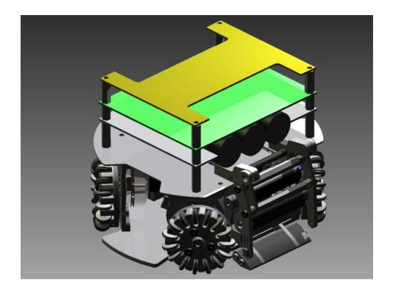
With the overall design of the 2011 fleet done, the RoboJackets decided to work upon a new model of robot, building upon past years experiences, and implementing new features to improve our competitiveness.
3.2 Chipper Redesign
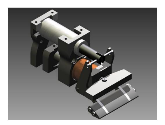
One of the first major redesigns for the 2013 prototype was improving the chipper geometry. In order to open up the possibility of more plays the team agreed upon changing the chipper design to increase the maximum vertical height. This would allow us to do more chip pass/defending plays , at the cost of eld long chip goals. The team felt that the benets of this change outweighed the losses. The changes were made by moving the pivot point to a lower location, and changing the prole of the arms. These changes can be seen in Figure 5. In addition to improving the chipping height the updated chipper in conjunction with the new dribbler allows us to dribble on the chipper boot. This improves ball control, and allows the potential of a ball centering mechanism by only changing the prole of the chipper boot.
3.3 Drive Module
The drive motor modules still posed problems for the mechanical team, even with the updated changes over the 2011-2012 year. The main two problems were identied as
- Back shell separation from modied drive motors
- Loosening of omni spacer
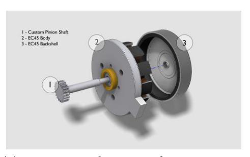
Back Shell separation To x the separation of the back shell from the modied pinion shafts we tried the application of an epoxy compound to improve the friction force of the press t. While this worked for the duration of the competition in Mexico, continued application has shown to weaken over time, forcing us to search for new solutions. The current improvement which has shown the most promising results are changes to the diameter of the pinion shafts. The current shaft has a diameter of 3.940mm at the press t location. We have increased that amount signicantly up to 3.995mm. This new design of the pinion shafts have yet to be implemented, however, we have strong reason to believe this change will x our current problems due to the reliability of the 2008 design, which has shafts with the updated diameter size.
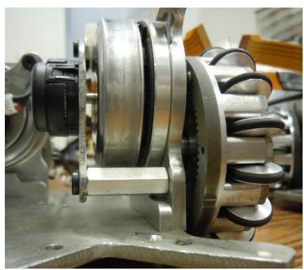
Loosening of omni spacer The spacer which attaches the omni wheel to the drive module has been continuously loosening over years. Past attempts of applying Loctite to the threads, and even welding the spacer to motor module have failed with time. Thus we decided to change the design of spacer to thread itself into the drive module. This also reduces the complexity of machining, allowing us to bring down the costs of the robots.
3.4 Developments Toward New Dribbler
In order to improve ball control, and prevent the ball from bouncing on the robot's dribbler, we have replaced the xed dribbler arms with passively damped arms. The goal of the damping system is to absorb the translational energy of the ball and transform it into mechanical energy which deforms a spring. The new dribbler design features an actuating set of arms each attached to a torsion spring. In order to prevent prolonged oscillation of the ball's position following contact with the dribbler, we need to make it make it critically dampening.
In order to achieve critical damping, we will test springs with different spring constants. Because the frequency of oscillation of the coupled ball and dribbler system will depend on the velocity of the incoming ball, the dribbler will be tested with different incoming ball velocities. In our test setup, one of our robots, will kick the ball at varying speeds towards a receiving robot that has a damped dribbler. The ball will pass through a speed gate in order to calculate its exact velocity. Each of the springs tested will be rated by how long it takes for the ball and dribbler to achieve steady state, with the goal being to minimize the amount of time it takes to achieve steady state. We will perform the test on multiple different kinds of carpet, since every carpet has a different coefficient of friction, which will influence how the ball behaves once captured by the dribbler. In order to compensate for different types of carpet, we have made the dribbler design adjustable. This allows us to change the tension of the spring, without having to replace it.
4 Electrical
This year we have made several changes and improvements over last year's electronics on our robots. The 2011 fleet represented a major design upgrade for electronics and these improvements were used to retrofit our 2008 fleet. Rather than perform a complete overhaul of our electronics, we strove to improve the reliability of the robots to allow the software team to test code on real robots more often. We also began development of a 2013 prototype control board and kicker board with more drastic design changes.
4.1 Motor Drivers
The 2011 control board has had issues in the past with FETs and FET drivers failing due to over-current and shoot-through [2]. Because motors are switched quickly, they experience a large $\frac{dI}{dt}$ , which causes the inductive windings to create a large transient current in the opposite direction to normal current flow. This current can destroy FETs and can sometimes propagate all the way to the FET drivers. This problem was observed whenever the robot was commanded to make very fast changes in velocity. To combat this effect, the new control board features transient voltage suppressors (TVS) that block large voltage spikes from the motors [1]. Each FET also has a second redundant body diode to ensure that body diode inside the FET does not break down. More line capacitance was added to help absorb transients as well.
4.2 Sensors
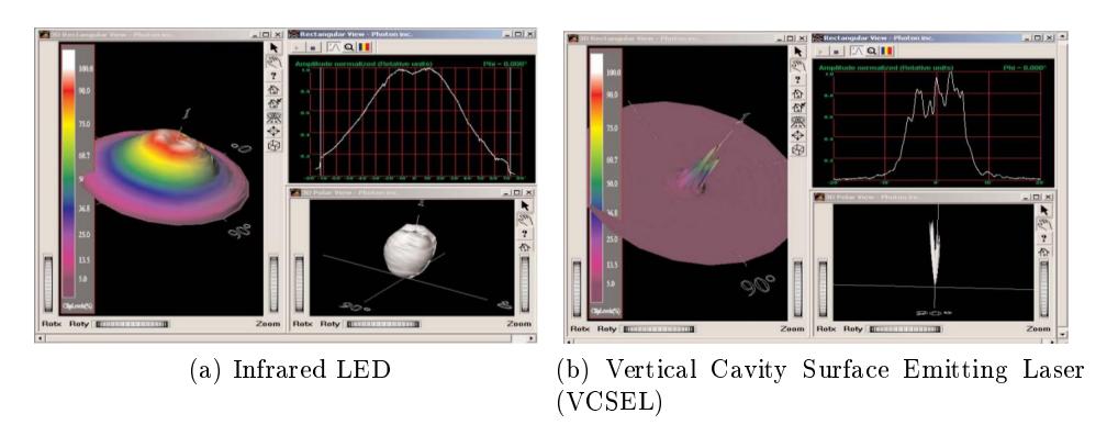
In previous years, we detected ball possession with a break-beam sensor under the dribbler bar. This sensor consisted of an infrared LED and a phototransistor. Previously, this sensor was frequently broken by contact with other robots because the sensors had to be in an exposed location. A failure of the ball sensor gave the same indication as ball possession, requiring heuristics on the control computer to determine whether a particular robot's ball sensor was damaged. The new mechanical design better protects the sensors. The new electronics can detect four classes of ball sensor failure: emitter open, detector open, detector shorted, and dazzling (excessive ambient light). If the emitter or detector is mechanically damaged, the most likely result is an open circuit which can be detected and reported, allowing the robot not to be chosen for ball-handling tasks during gameplay and to be replaced at the next opportunity. To compensate for varying ambient light, alternating measurements are made with the emitter on and o. If the emitter-on measurement is unexpectedly high, the most likely cause is excessive ambient light, and the ball sensor will not report constant possession. By detecting ball sensor failure, we can avoid certain cases where a robot attempts to handle a ball that it does not actually possess. At RoboCup 2012 in Mexico City, our ball sensors had a hard time dealing with the large amount of IR light from the eld lights. We spent a lot of time attempting to calibrate the sensors against the unusually high ambient IR light, but had problems in shielding the phototransistor, as the ambient IR light was almost as intense as the IR LED. Additionally, scattered IR light o the ball from our LED sometimes created false positives. This year, we have switched from an LED to a VCSEL (Vertical Cavity Surface Emitting LASER) to do ball detection [4]. This allows us to recess the phototransistor further back into the dribbler assembly and to reduce the eects of ambient or scattered IR light. Rather than just emit a single beam from the VCSEL, we use an LFSR (Linear Feedback Shift Register) to pulse the beam in a quasi-random fashion. Since the receiver knows what the bit sequence being generated by the LFSR is, it can look for that pattern and reduce false positives from external light. The quasi-random nature of the sequence makes it almost impossible for an ambient source to match close enough to cause a false positive. This sequence can be extremely fast, as VCSELs can pulse for as short as 200 picoseconds, while LEDs can only pulse down to about 500 nanoseconds. In addition to a more precise source, a new phototransistor with a higher dynamic range was also chosen.
In 2011, we introduced an IMU to help acquired more precise motion and position estimation information from the robot. That IMU consisted of an IMU-3000 three axis gyroscope. This year, we have upgraded the IMU to a six axis model that contains a three axis accelerometer and a three axis gyroscope (MPU-6050). An additional three degrees of sensing will allow us to more precisely locate the robot. The accelerometer will also let us detect slippage and greatly improve traction control.
An optical ow sensor was added to the bottom of the robots to help further resolve information about traction and slippage. The sensor works similarly to an optical mouse, and allows the software to observe movement independently of vision. If the robot leaves the cameras' eld of view, the optical ow sensor may be able to maintain a suciently accurate position estimate to allow it to move back onto the eld. The optical ow sensor also has an increased resolution of movement, and is capable of detecting movements that vision might not see. We are attempting to use the optical ow sensor to improve the robot's pose estimate to allow for more precise motion control. Our plan for future development is to move pose estimation and low-level motion control onto the robots to minimize latency and to allow us to take advantage of the motion estimates provided by the IMU and optical ow sensor.
4.3 Kicker
The 2013 kickers were a continuation of work started in 2008 and 2011. Our robots use two solenoids for ball handling: one for kicking forward and one for chip-kicking upwards. In 2011, each solenoid was operated by discharging a pair of capacitors through an IGBT into the solenoid coil. The 2011 kicker allowed for improved control parameters. Kick strength can now be determined by the length of the current pulse into the solenoid. This current can be regulated to an adjustable value, allowing longer pulses with more carefully controlled current. This also allows the maximum current to be restricted to a value that will not damage the IGBT even with a shorted coil. The current limit is implemented by measuring the coil current with a hall eect current sensor (Allegro ACS758) and switching o the IGBT when the current exceeds the limit. When the current falls below the limit minus a small hysteresis value, the IGBT is turned back on. The robot can capture coil current and capacitor voltage traces during a kick for later analysis to facilitate kicker solenoid and electronics development.
Last year, the RoboCup SSL rules were changed to put a limit on ball speed. Previously, we were capable of kicking the ball in excess of 12 m/s. The new cap limits the speed to 8 m/s, so the 2013 kicker redesign was in part a response to this. By using more and smaller capacitors, we can prevent wasting weight, space, and money on larger capacitors that are now unnecessary. The 2013 kicker has a similar form factor to our 2008 kickers, with three 250V, 820 µF capacitors lying horizontally. This saves signicant space around the wheel base and allows the mechanical design to have more exibility in dribbler size and wheel spacing. It also incorporates innovation from our 2011 design, which allows more data to be collected and provides us with deeper analytics on performance.
Previous kicker boards were all electrically isolated for safety reasons. Unfortunately, this resulted in a higher level of complexity and more potential failure points. It also prevented full electrical shielding on the PCB. In 2011, the decision was made to abandon the full galvanic isolation in favor of a new design, while maintaining safety. A yback topology with the LT3757 was used for several reasons. We wanted to maintain charge on the capacitors, continue charging the capacitors even if they were close to their target voltage, and gracefully handle the short circuit current load condition that occurs when the capacitors are empty. The yback regulator was implemented using the same transformer that was utilized in a previous design iteration because of it's proven reliability and our existing inventory. To provide additional safety, a red LED was added to the kicker along with a discharge switch. If the red LED is on, team members know that the capacitors are charged and the board is potentially dangerous. By pressing the discharge button, all remaining energy in the capacitors is dumped into the solenoid, and the board is rendered safe.
Last year, we encountered a problem with IGBTs failing after some time. Two IG-BTs stacked in parallel provided the switching from the capacitors into the solenoid load. It was determined that the current rating of these IGBTs was not sucient for some of the transient currents that could appear during normal operation. In the 2013 design, the stacked IGBTs were replaced with a single IGBT with a higher current rating than the original two combined. This not only prevents the IGBTs from failing, but also reduces part count and cost.
Improvements to the kicking eciency have also been considered. By introducing an additional IR breakbeam sensor behind the kicker assembly, we can detect full extension of the solenoid and shut o the current through the solenoid to prevent an oscillation from occurring near its peak extension. The oscillation from this will not only consume more energy but will also retract the kicker before most of the energy could be transferred to the ball.
4.4 Battery
Our 2013 robots continue to be powered by lithium polymer battery packs. Our 2008 robots used nickel metal hydride batteries which could not provide enough current to accelerate the robot rapidly under some circumstances. The LiPo batteries are smaller, lighter, and can provide more current without the supply voltage dropping excessively. Since LiPo batteries must not be discharged below a certain level, the CPU monitors battery voltage and sounds an alarm if the battery pack is discharged to the minimum safe level. This year saw the addition of circuitry to shut down the robot when the battery voltage drops below a certain threshold. There have been problems before with robots being left on by accident, and if no one is around to hear the alarm, the battery continues discharging to a dangerously low level and is damaged. Automatically shutting down the robot prevents this problem and provides an additional safety feature for our robots.
5 Summary
For the 2013 season, we have made a variety of upgrades to our 2011 eet and designed a new 2013 robot, incorporating lessons learned in the 2012 Mexico City competition deployment, as well as future-looking improvements. We have improved the software to be more resilient to hardware failure cases, as well as directly addressing shortcomings of the previous systems.
References
- S. W. Colton. Design and prototyping methods for brushless motors and motor control. In Masters Thesis in Mechanical Engineering.
- Robojackets RoboCup SSL Team. Robojackets robocup 2011 team description paper. Technical report, Georgia Institute of Technology, 2011.
- Robojackets RoboCup SSL Team. Robojackets robocup 2012 team description paper. Technical report, Georgia Institute of Technology, 2012.
- OPTEK Technology. Vertical cavity surface emitting laser in lateral package.