Skuba 2013 Extended Team Description
Thanakorn Panyapiang, Ratthapoom Thanomyart, Kanjanapan Sukvichai
Department of Computer Engineering, Faculty of Engineering, Kasetsart University; Department of Electrical Engineering, Faculty of Engineering, Kasetsart University; 50 Ngam Wong Wan Rd, Lat Yao Chatuchak Bangkok 10900, Thailand
Abstract This paper gives description of Skuba, A RoboCup Soccer Small Size League robot team. The system is designed under the RoboCup 2013 rules in order to participate in the RoboCup 2013 which hold in Netherlands. The system of our team consist of several components which we describe in each section.
Introduction
Skuba is a RoboCup Soccer Small Size League robot team from Kasetsart University, Thailand. The team has participated in RoboCup Soccer Small Size League since 2006. We got 1st place four consecutive times since 2009 to 2012. We also participated in the RoboCup Iran Open 2011 and RoboCup Japan Open 2012. Our team got championship from both competitions.
Our system is composed of two main components : robots and software. Robot consist of several hardware such as electronic boards, capacitors, motors and mechanical parts. Software is the artificial intelligence system. It use data from global vision system run by SSL Vision, the shared vision software, to make decision and choose a suitable strategy for particular situation and send commands to each robot via wireless signal.
This year, We decide to build new robots with the new design because our robots don't have any major change since RoboCup 2008. In the RoboCup 2012, Our robots had serious problems when it face other team robots which are newer and more powerful. For instance, The robot was pushed by opponent into the defense area that cause causing penalty. Thus, the robot hardware is needed to be improved in order to obtain a better performance and has more power to eliminate those disadvantages.
In order to improve robot performance, more power motors are selected and robot body including electronics and mechanics is redesigned because it has to be compatible with the new motors.
In addition, we do the experiment that apply data mining technique to learn opponent behaviors from game log which we record from real match.
Robot
The robot The robot has four omni-directional wheels driven by 50 W Maxon flat brushless motors. The dribbling device is round bar cover with silicone tube connect to 30 W Maxon EC brushless motors. The kicker consists of flat-kicker and chipkicker. The flat-kicker uses solenoid to kick the ball with maximum ball speed is 14 m/s. The chip-kicker uses flat solenoid which can kick the ball up to 7.5 m.
Main board
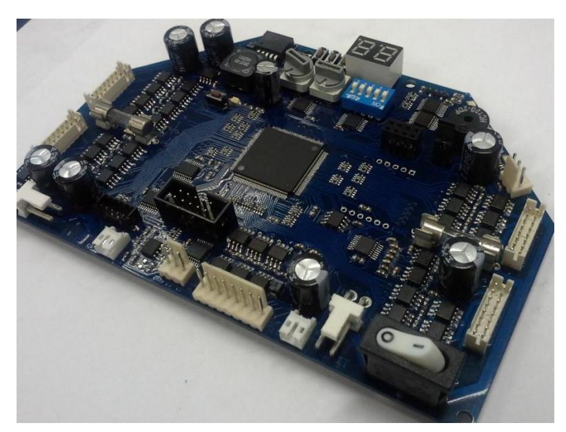
The main board consists of a Xilinx Spartan-3 XC3S400 FPGA, motor driver, user interface, some add-on modules and debugging port. The microprocessor core and interfacing logic for external peripherals are implemented using FPGA in order to handle the low-level control of the brushless motor such as velocity and position control. The main electronics board receives commands from the main software on a computer. The board integrates the processing components together with the power components to keep the board compact and minimize wiring. With limited space, almost components are in small SMD packages. However, these components still large enough for hand soldering with conventional tools.
Driving Motors
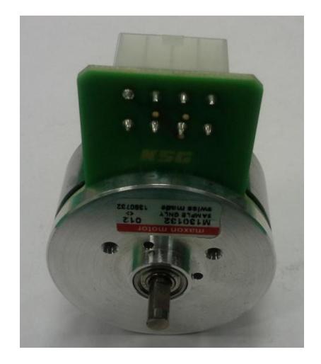
The driving motor is 50 W Maxon flat brushless motors with a custom backextended shaft for attaching encoder wheel. The motor itself can produce a feedback signal from hall sensors for measuring wheel velocity. However, this multi-pole motor sends only roughly 48 pulses per revolution; therefore, this motor is equipped with an US Digital E4P encoder which have higher resolution of 1440 pulses per revolution.
Wheels
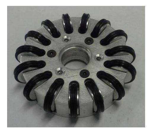
The wheel has a diameter of 50.8 mm which its cover is made from aluminum and its base part is made from polycarbonate, the light weight material, with fifteen rollers. Double seal o-ring is used for each roller in order to get more friction. All of these components, leading to the light weight and better tracking wheel and finally we have a light weight and better robot. We use pins to fix the position between the cover and the base to reduce the positioning error.
Kicker
The kicker consist of flat-kicker and chip-kicker each kicker. The flat-kicker is a cylindrical shaped solenoid attached to a curved kicking plate. The chip-kicker is a flat solenoid attached to 45 degree hinged wedge which can kick the ball up to 7.5 m. Both kickers are driven by four 1200μF 250 V capacitors. Each kicking device is controlled by separated board below the middle plate.
Kicker board
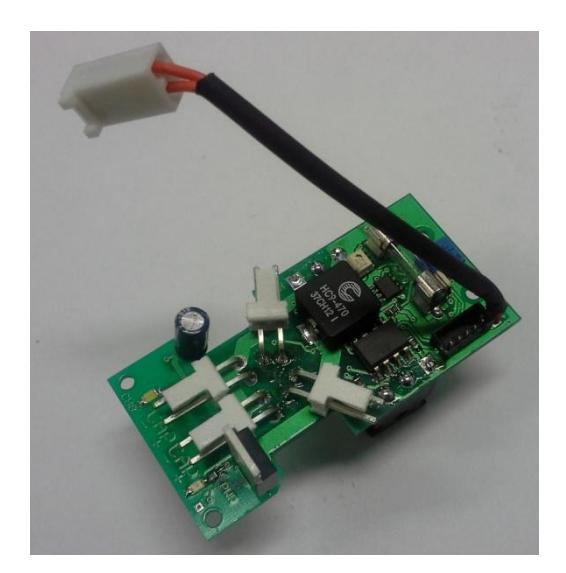
Kicker board consists of power electronic components which are controlled directly from the FPGA in the main board. The board requires PWM signal for switching circuit and another PWM signal to impulse the kicker with the desired kicking force. The switching DC converter uses a soft-start method to reduce inrush current when the capacitor is empty. This method is done by starting with the low duty cycle and ramping up over the time until it reaches the limit. The ramping starts again when the kicker is activated.
Dribbler
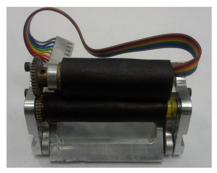
The 30 W Maxon EC brushless motors is use as dribbling motor. The motor, which can run up to 37700 rpm , attached with 28:4 planetary gearhead. The dribbling bar is made from aluminum rod with diameter 10 mm and cover the ball 20% of diameter.
Suspension
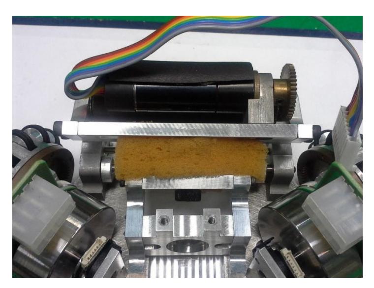
The entire dribbler assembly is hinged with the chassis plate which is attached with a sponge damper. We use adjustable screw as the stopper, allowing the suspension to swing about 6.5 degree. This suspension system makes the robot able to receive the fast moving ball in passing skill. Both outer sides of the suspension arms are equipped with the covers to protect the infrared sensors from damaging.
Software
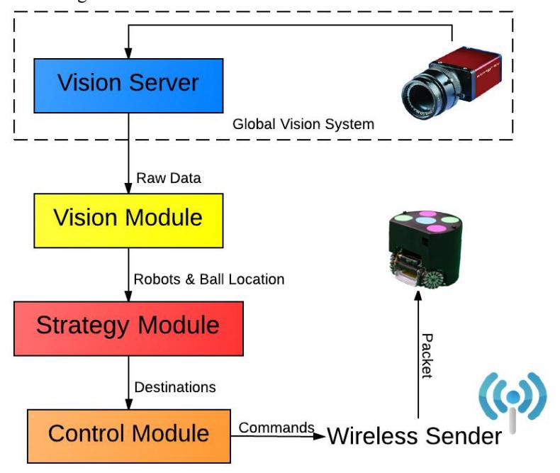
The overall software architecture show in Figure. 4 The software system consists of several modules organized in multi-layer. The Design of software system is based on Cornell Big Red 2002's software.
Vision Module
Vision Module takes vision data from Vision server and extracts velocity from those data. It also predicts future location of robots and the ball. Our total system latency, measuring from the period between command velocity and raw velocity, was approximately 133 ms (7 frames). When our robot move at the maximum speed, that is up to about 3.5 m/s, the distance between real robot position and the robot position from vision data will grow up about 47 cm. In order to correct this error we have to estimate the positions and orientations of the robots.
For opponents and ball, two states Kalman filter is applied to predict opponent robots and ball location with more accuracy location.
Strategy Module
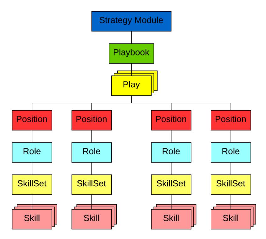
Strategy Module use vision data from Vision Module to figure out which one is the best tactic for particular situation. The structure of this module is based on STP framework
The module contains several Plays which store in 'Playbook', a collection of Plays, when Play was executed it call the 'Role' of existing Position (For example, Goalkeeper, Defender). Then the Role runs Skill, which keep in 'SkillSet', for related robots. The architecture of Strategy Module illustrate in Figure 8.
Role Definition
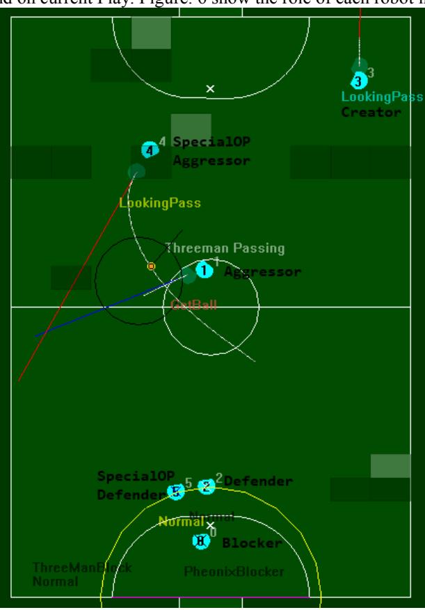
There are four main robot roles : Aggressor, Blocker, Creator and Defender. Each role has specific duty in the field.
Aggressor is the most active role. It always looking for the ball. See a robot go up to an opponent who has the ball, either to screen him from our goal or strip the ball away and try to score whenever possible.
Blocker( or Goalkeeper) always remains in goalie box to prevent opposite team from scoring by blocking or intercept the ball. Another duty of Blocker is clear the ball when inside the goalie box.
Creator is a robot that supports the Aggressor. Main role of Creator is to create attacking opportunities. Creator move into position that has high chance to score if Aggressor pass to and rebound the shooting that was blocked by opponents.
Defender is the position that dedicated for defense. This player always remains around our defense zone and cooperate with Blocker to stop opponent from scoring. Defender try to cover area as much as he can to ensure that the opponent robots can't score. Moreover, Defender also attempts to clear and intercept the ball whenever possible.
There is another role call 'SpecialOp' which can play as extra Defender, Aggressor or Creator depend on current Play. Figure. 6 show the role of each robot in real game.
Control Module
Control Module receives destinations from Strategy Module and make robot go to those destinations. This module also use vision data from Vision Module as a feedback for Closed Loop control.
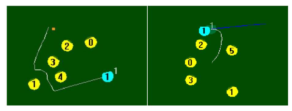
The important component of Control Module is path planning algorithm. We have implemented two path planning algorithms : Rapid-Exploration Random Tree(RRT) and Sub-goal Path Planning. Figure. 7 show paths generate by RRT algorithm(left) and Sub-goal algorithm(right).
Wireless Sender
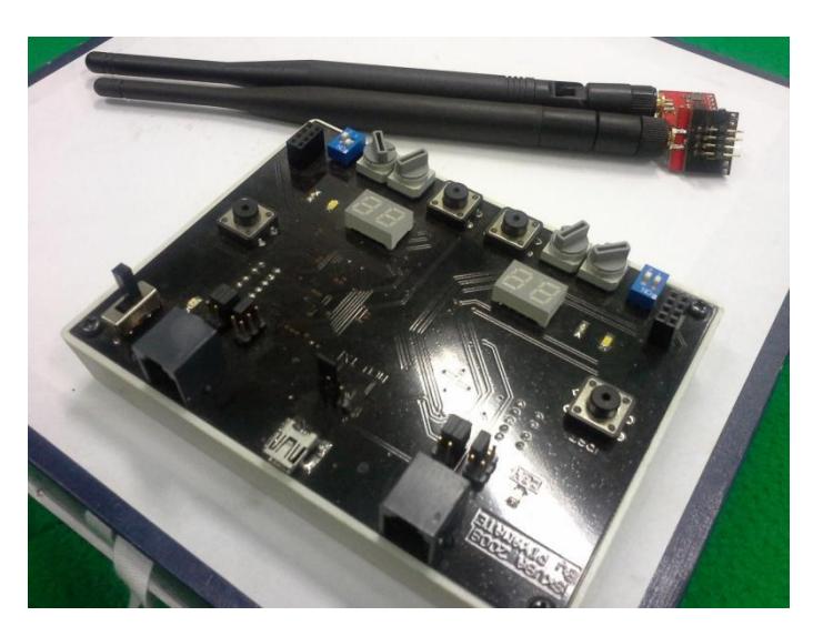
Commands which is generated by Control Module will be packed into single packet for each robot. Then, the wireless board will distribute packets via wireless signal and the robot will receive only the packet that send for itself. In addition, We also get real-time information, for example battery life, from robots by let it send wireless signal and use the wireless board to receive those data.
Formation Plays Recognition via Time Series Data Mining
Skuba has system to record game state sequence. At every frame the log includes the location and orientation of each of own and opponent robots, the location of the ball, and any referee command, such as penalties, stop game, and goals. At a frame rate of 60Hz and with 20mn games, the logs result in a considerable amount of data.
Log contain more than 70,000 entries for 20 minutes game. We divide the game into an Episode which start from frame $t_0$ when possession $give$ to team by referee command( direct or indirect ) and end at time $t_n$ when game stop by referee's stop command.
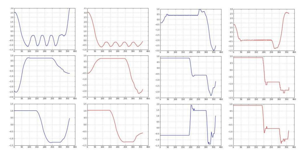
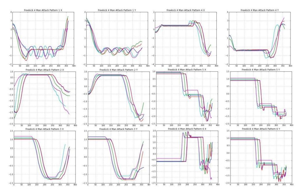
We extract episodes from log file and take only episodes that start with direct or indirect freekick for opponent and select frequently occurrence formations to be training sets. In our training sets, we have 5 examples of all opponent robots position sequence either x and y axis from start to end of episode.
Similarity between robot movements
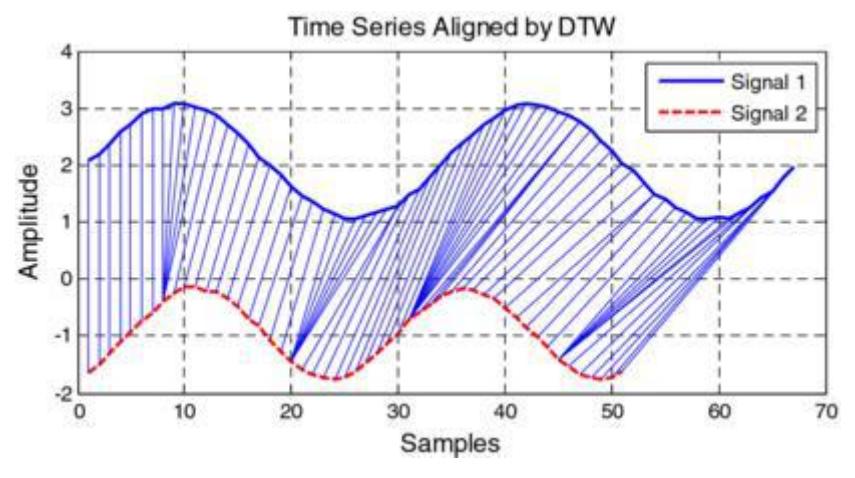
To identify is robot move in the same pattern we need a distance measure. In some domains a very simple distance measure, such as Euclidean distance will suffice. However, it is often the case that two sequences have the approximately the same
overall component shapes, but these shapes do not line up in X-axis. In order to find the similarity between sequences, we must "warp" the time axis of one (or both)sequences to achieve a better alignment. Dynamic time warping (DTW), is a technique for efficiently achieving this warping.
Construct Sequence Model
Our training sets have 5 examples of same formations for each example has 6 sequence( 6 robots ). To construct the model for each robot, we use Dynamic Time Warping to measure distance between other sequence in the same group and select the sequence which has lowest total sum as representative of the sequence.
Apply Model
After build the model , A formation $F$ is ${f1,..,f6}$ where $f_i$ represent sequence of robot $i$ position every frame. Let $C$ be the set of behaviors pattern of opponent robots where $C = {c1,...,c6}$ : $C_i$ is behaviors pattern of robot $i$ which is a set of x-postion and y-position.
The distance between sequence $f_i$ and $c_j$ is less than threshold $\alpha$ both trajectory consider to be the same. If all behaviors pattern of formation $F$ similar to at least one $Ci$ on $C$ then both $F$ and $C$ are the same formation.
References
- Thanakorn Panyaping ,Krit Chaiso, Kanjanapan Sukvichai and Phawat Lertariyasakchai : Skuba Extended Team Description. In Proceeding of Robocup 2012.
- Eamon J.Keogh and Michael Pazzini : Derivative Dynamic Time Warping.
- Can Erdogan Manuela Veloso : Action Selection via Learing Behaviors Pattern in Multi-Robot Domain.