2013 Team Description Paper: UBC Thunderbots
Andrea Palmer, Christopher Head, Matthew Lai, Henry Poon, Terence Lin, Andrew Wong, Brian Wang, Jonathan Fraser, Komancy Yu, Christian Villar, Sandy Lum, Tamer Kalla, Anna Gabaldon, Alice Lam, Somik Ghosh, Sarah Holdjik, Wei Tai, Wei Yi Su, Bonnie Lee, Chen Wu, Diana Nino, Koushik Peri, Robin Yoon, Ethan Jang, Patrick Wong, Bio Cho, Raymond Tang, Amy Leson
The University of British Columbia
Abstract This paper details the 2013 design of UBC's Small Size League team to be entered at RoboCup 2013 in Eindhoven, the Netherlands. The main focus of this year was to increase reliability of the electrical systems, decrease the size and increase performance of the mechanical systems in the robot, and to develop the team's defensive strategy, using the triangle-attack formation.
INTRODUCTION
UBC Thunderbots is an interdisciplinary team of undergraduate and graduate students at the University of British Columbia. Established in 2006, it pursued its first competitive initiative within the Small Size League at RoboCup 2009. The team also competed in RoboCup 2010, 2011, and 2012, and is currently seeking qualification for RoboCup 2013. Over the years, it has made significant developments of its team of autonomous soccer playing robots. This paper will outline the progress in implementation of the current model of robots, focusing on the mechanical, electrical and software components with particular emphasis on the dribbler system, the electrical communication and the artificial intelligence (AI) plays.
ELECTRONICS
(Described in subsections below)
2.1 Communication
One goal for the 2013 communication system is to improve performance. In 2012, the team switched from Digi International's XBee series of radios to the Microchip MRF24J40 series [1]. These parts have proven to be suitable, and will be used at RoboCup 2013. In the RoboCup 2012 Team Description Paper [1], it was proposed to use beaconed coordinator mode and guaranteed timeslots to achieve precise control over spectrum timeslicing. This was not implemented before RoboCup 2012, but is planned to appear in the 2013 control. There will also be investigation into different queueing disciplines for reliable packet delivery to multiple robots, such as per-robot packet queues, to reduce the performance impact of non-responsive robots and improve fairness. Finally, the USB portion of the communication protocol will be examined to determine if there are any changes that can be made to improve performance—for example, counterintuitively, bulk endpoints may in fact provide better performance than interrupt endpoints, despite interrupts endpoints having guaranteed bus bandwidth. The reason for this is that interrupt endpoints will fail if bandwidth cannot be precisely reserved, forcing descriptors to be set up for the least common denominator; bulk endpoints, on the other hand, have no reserved bandwidth but can use any bandwidth that is available—which is often substantial—and can even execute multiple transactions in a single frame. These small modifications should incrementally improve performance of the communication system.
The team's second goal with our communication system is user-friendly automatic configuration. At present, each robot is given the channel number on which to communicate as well as its own pattern number. In the future, all per-robot configuration data will be removed. The need for a channel number will be eliminated by having the robot slowly iterate channels at startup until it finds a beacon packet sent by the base station (which will be operating in beaconed coordinator mode); to avoid interference when passing through other teams' channels, a unique feature of the MRF24J40 will be used, which allows transmission of acknowledgement frames to be disabled. Pattern number configuration, on the other hand, will be eliminated by using the FPGA's built-in serial number. This serial number will be converted into a MAC address for use by the radio, which will then send an association request to the coordinator (base station). The base station will then indicate the robot's pattern number by means of the assigned 16-bit 802.15.4 address. Thus, the mapping between FPGA serial numbers and robot pattern numbers can be maintained purely in host software. These optimizations will eliminate the inconvenience of losing configuration data each time new firmware is loaded on the robot, as a side effect of erasing the Flash memory chip.
2.2 Lateral Ball Position Sensor
In 2012, the Lateral Position Sensor (LPS), which could detect how far to the left or right of centre the ball was positioned on our dribbler, was to be introduced [1]. Unfortunately, it was not included on the 2012 robot. The sensor is currently completed and ready for testing, and is intended for use at RoboCup 2013. Expectantly, this will allow for a number of abilities, including providing the AI with the ability to track the ball even in the face of camera data loss due to occlusion to computing or even controlling kick direction much more precisely by characterizing the mapping between lateral position and outbound direction.
2.3 Robustness and Safety
In both 2011 and 2012, there were many reliability problems with the electrical components. Shortly before RoboCup 2012, the likely cause was determined: regenerative braking drove power supply rails above the operating maximum ratings of some components, primarily the transistor gate driver chips. While regenerative braking should not cause significant power rail rise when the robot is powered by a battery (since the rising rail should simply recharge the battery), when powered by a laboratory power supply unit, more than ten volts of rail rise was observed. This year, the hardware was designed such that it would be robust against regenerative braking. Two main steps were taken to address this. First, the design was audited to find and replace any component that would be powered by an unregulated power rail but was not rated for an operating maximum voltage of at least 30 volts. One such part was the Microchip MCP1415, a MOSFET gate driver that was used for capacitor-charging, kicking, and chipping paths which has an operating maximum voltage of 18 V; it was replaced with the Micrel MIC5020, rated to operate up to 50 V. The MOSFET drivers used in the motor drive paths from 2011, Microchip TC4469s, with an operating maximum voltage of 18 V also needed to be replaced; these were replaced with STMicroelectronics L6234 chips, which combine power transistors and gate driving hardware in a single chip rated for operation up to 42 V. With the current component selection, the circuits should be operating within specifications with supply voltages of up to 30 V. The second step taken to address reliability was to add a transient voltage suppressor diode with a 25 V breakdown to help dissipate power in the event the rails rise too high. Finally, fuses were added to a few locations, allowing for faster identification of which part of a board has failed—or, in the event of a wheel motor driver, perhaps even continue playing a game after a motor driver has completely destroyed itself.
Safety has always been taken seriously in the design of capacitor charging circuit, as it operates at 240 VDC. In the past, a number of features have been combined to reduce the chance of shock to team members operating the robots, including indicator lights showing when the capacitors are charged and automatic discharge capabilities that activate as soon as the robot is removed from the field or the game is halted. The automatic discharge dissipates accumulated power through the kicking and chipping solenoids fast enough to completely drain the capacitors within a few seconds, but slowly enough to avoid actually moving the solenoid plungers and potentially causing injury by physical impact. Unfortunately, there are still a few situations where the robot was shut down in an unexpected manner and it was unclear as to whether or not the capacitors remained charged. To completely eliminate this possibility, a last-resort discharge system was added this year in the form of a relay whose normally-closed contacts connect the capacitors directly to a series-pair of 68 Ω resistors, reducing the capacitors to a safe charge level in less than one second.
Finally, in the past there were reliability problems with the connectors used on the wheel motors, optical encoders, and break beam sensor. Some of these connectors are only rated for a very small number of insertions and removals before they make potentially poor contact, while other connectors are very small and fragile. To reduce the incidence of connector failure, a third circuit board was introduced, which was termed the "breakout board". This board sits below the main board and charger/kicker/chipper board and attaches to all unreliable connectors—the wheel motors, the optical encoders, and the break beam and lateral position sensor. As this board has nearly no electronic components on it, it is expected to be extremely reliable and virtually never need removing from the robot, thus saving on connector cycles. To connect the main board to the breakout board, a Hirose FX6 connector is used, which offers 60 pins in a relatively small space and just 5 mm spacing between boards. These connectors provide a single point of disconnection with a high cycle count rating, allowing the main board to be removed from the breakout board easily and frequently without worrying about fragile cables and connectors. One other advantage to the breakout board is the freedom to reduce the area of that board without suffering from increased component density; this freedom was used to cut 45° angles in the two back corners of the board to match the mounting angles of our wheels, thus reducing the amount of twisting in the motor cables—twisting which had, in previous years, caused motor cables to split where they entered the motors.
2.4 Automated Component Testing
Certain parts of robots fail more often than other parts; years of experience show that some of the most failure-prone components are optical encoder wiring, motor Hall sensor connections, motor phase drivers and connections, break beam sensors and highvoltage components. In the past, there have been informal checklists for checking these components; each robot would be put on a table and all these components checked individually by hand. This procedure is time-consuming and often inconsistent. This year, an automatic testing procedure will test most of or all of these components before a robot is deemed ready for competition.
Some components can be tested continuously while the robot is operating. Optical encoders and Hall sensors fall into this category. The Hall sensors can detect that a wheel is rotating (albeit with low resolution); if this occurs and the optical encoder does not report a matching wheel rotation, the optical encoder is clearly faulty. The Hall sensors themselves, on the other hand, generally manifest failure as a specific sensor becoming stuck at a specific polarity; because there are three Hall sensors but only six legal readings (the all-ones and all-zeroes readings being illegal), a stuck sensor will eventually yield an illegal reading, which can be detected. Problems causing high leakage from the capacitors can be caught by monitoring operation of the charger in top-up mode.
Other components cannot be tested during normal operation but can be tested automatically when the robot is isolated off-field. Additional parts of the high voltage circuitry can be tested by actually firing the kicker and chipper and monitoring the amount of capacitor energy consumed. Break beam sensors can very likely be tested by firing the kicker and observing an expected momentary interruption of the beam by the kicker head itself. Finally, motor phase driving paths may be testable by driving specific patterns of phases in specific sequences and using the Hall sensors to check whether the wheels properly rotate to the expected positions.
MECHANICAL DESIGN
The maximum dimensions for this year's robot can be found in Table 1.
Table 1: Maximum Robot Dimensions
| 148 mm | MAXIMUM HEIGHT |
| 178 mm | MAXIMUM DIAMETER |
| 18.1% | MAXIMUM BALL COVERAGE |
3.1 Solenoid
The function of the kicker is to allow the robot to shoot the ball across the field. The major change in this year's robot is the implementation of smaller cylindrical solenoids, as opposed to last year's larger flat solenoids. The motivation behind this is to reduce the size of the mechanical assembly. The new setup also speeds up the assembly process and solves tolerance issues that were encountered during assembly. The kicker uses a push-type solenoid to impart an impulse on the ball, as seen in Figure 1.
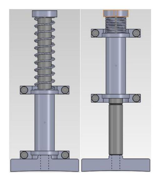
Table 2: Solenoid Design Parameters
| Plunger | |
|---|---|
| LENGTH: | A longer plunger allows more magnetic energy to be stored inside, but increases the plunger's inertia. Therefore the trade-off here is between energy storage and weight. |
| DIAMETER: | The diameter is affected most by mechanical considerations because the plunger must be able to withstand high loads during gameplay. |
| MATERIAL: | Different materials interact with magnetic fields differently. For example, stainless steel does not react strongly, while mild steel does. |
| STARTING POSITION: | The starting position affects the initial force exerted by the solenoid. If the plunger is too far out, the force will be very low and the travel distance high. If the plunger is too far in, the force will be high but the travel distance low. |
| Outer Casing | |
| MATERIAL: | An outer casing can help direct the magnetic field outside of the coil to improve the solenoid's performance. |
| THICKNESS: | Higher thickness means that there is more material to interact with the magnetic field. Space constraints are an issue. |
| Coil | |
| LENGTH: | A long coil can increase the inductance of the coil, which is a very effective measure of how well a solenoid can perform. |
| TURNS: | More windings or turns can increase the magnetic force, but also increases resistance, which can decrease the force. |
| WIRE DIAMETER: | A large wire diameter allows fitting in less turns and decreases resistance. These two parameters are conflicting and results in a very important trade-off that is difficult to account for analytically. |
| OUTER and INNER DIAMETER: | This dictates the amount of physical space available for windings. More windings or turns can increase the magnetic force, but also increases resistance, which can decrease the force. |
Design Challenges The goal is to discharge the maximum amount of energy into the solenoid as the plunger moves from the start position to the solenoid's midpoint. Knowing the coil resistance and inductance means that the capacitor current discharge time can be approximated. However, because the plunger speed cannot be accurately predicted using the model outlined above, it is impossible to determine whether or not the plunger moves from the start position to the solenoid's midpoint in the determined discharge time. The next section discusses an alternative approach to solenoid design.
Finite Element Method Magnetics Because of the difficulty in modelling a solenoid analytically, much of the design of the solenoid was done using Finite Element Method Magnetics (FEMM) to determine how well the solenoid will perform. The design process is also highly iterative. A physical prototype then followed to confirm the physical testing to the simulation.
To determine suitable parameters for the solenoid, different parameters were varied and tested. The solenoid on the 2012 robot was used as a starting point [1]. Table 3 shows how two key properties in FEMM impacted the solenoid design.
Table 3: FEMM and its Impacts on Design
| COIL RESISTANCE: | A small coil resistance increases the peak current in the solenoid. A larger peak current results in a higher magnetic force (all other parameters held constant). |
| INITIAL AND FINAL INDUCTANCE: | Comparing the change in inductance between different coils offers a measure of relative performance. |
A limitation of FEMM is that the software performs time-independent simulations, which means it is unable to account for the changing current due to the capacitor discharge. Thus, FEMM is not able to predict plunger speeds with any useful accuracy.
Physical Testing Once confidence is reached with the simulation results, a physical prototype is constructed and tested. Testing is done by constructing the kicker assembly and using it to kick a golf ball. A custom-designed ball speed measurement device outputs the ball speed.
If the ball speed does not attain the league maximum value of 8 m/s, different features of the kicker, such as the stopper or the spring, are removed to determine how each component affect the ball speed. The spring design is based on the output of this testing. For example, if removing the springs during testing improves ball speed, the impact of the spring on the final design can be determined.
3.2 Dribbler
The dribbler has some of the most important functions on the robot including accepting incoming balls at varying speed and controlling the ball for kicking or chipping. The focus of this year's redesign was to optimize the performance of the dribbler when receiving the ball.
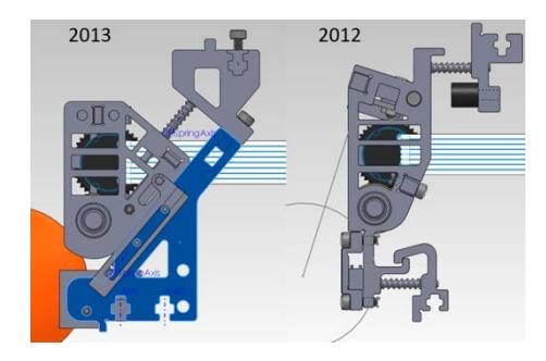
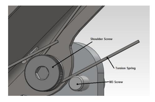
There were two main design changes from the 2011 dribbler [2]: to improve catching performance and dribbling maneuverability from its predecessor. Firstly, springs replaced the shock absorber from the 2011 dribbler as the shock absorbers were too stiff for the purpose. The other design feature that improved catching performance was that the dribbler was designed to move horizontally for maximum shock absorption as the springs are all horizontal. However, due to the contact between the golf ball and the roller, the force exerted on the dribbler still caused a rotational motion to the dribbler due to friction on the top shaft. Therefore, in order to achieve linear motion, the direction of the forces were taken into account.
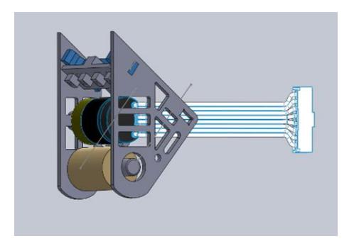
Absorption The 2013 dribbler, shown in Figure 2, has an angled sliding surface for the main body to slide along when absorbing an impact. This ensures longitudinal motion of the body along the springs and utilizes the springs for full shock absorbing capability. The initial position of the dribbler is slightly further forward compared to 2012 [1], which ensures that the roller is in contact with the golf ball before it touches the chipper plate. This guarantees the shock absorbing action occurs before the ball bounces on any hard surfaces (i.e. chipper plate). The angled configuration also provides a convenient feature for proper maintenance because if the two fastening screws aren't properly fastened, the main body will slide out indicating incomplete installation.
3.3 Chipper
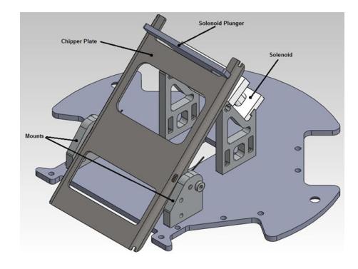
The main function of the ball chipper is to launch the ball above the plane of the playing field. The chipper also serves as a stop to prevent the ball from being pulled too far under the dribbler. Figure 4 shows the 2013 chipper system.
SOFTWARE
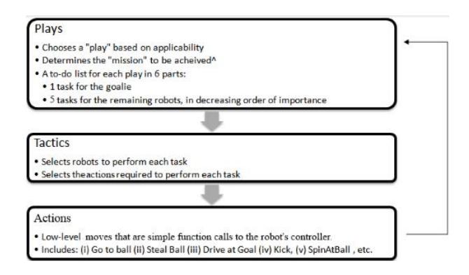
Building on the efforts of previous years, the main high-level decision-making model used is again the Skills, Tactics, Plays (STP) model, developed by CMDragons in 2003 [3]. After using the STP model for two years, the Thunderbots implemented an Actions, Tactics, Plays (ATP) model, outlined in Figure 6. Actions are simple function calls that can be freely used by any Tactic, in contrast to Skills, whose usages are strictly controlled by a Skill State Machine (SSM). The elimination of the SSM greatly simplified the software design and implementation, and added to tactical flexibility without incurring major loss of functionality.
4.1 Offense
The following outlines the advances made to the offensive strategy since 2012.
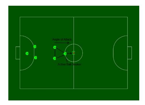
Triangle Attack Formation Inspired by the success of the defensive approach of utilizing two defenders and one goalie in a formation to guard the goal, the Triangle Attack Formation, shown in Figure 7, is a new approach for offensive plays developed to take full advantage of the sixth player. It uses three robots in a offensive triangle formation to cut through the opposing team's defence. Two of the robots are in place to support a third active, ball-seeking robot. A position for the triangle formation of robots to move to, in addition to the angle of attack of the formation, is chosen based on the distance from the enemy goal, shooting angle and how many enemy robots are in proximity. The formation of players will always actively seek an opening in the enemy goal to attempt to score a goal, while keeping the ball in the friendly team's possession. If the ball is not currently in team possession, the active ball-seeking robot will attempt to fight for the ball while the other two robots will support on either side and in turn seek the ball when it becomes free.
4.2 Defense
The defensive strategy for Thunderbots largely remains the same as 2012 [1], and has not been a high priority in this year's development plans. An Active Defence Tactic (ADT) was implemented to fight for the control of the ball with another enemy robot. This involves using the robot's rotation to knock the ball out of the control of the enemy's dribbler and send it to an open area of the field to be picked up by another friendly robot. This ADT is also implemented by the Triangle Attack Formation, particularly for the two supporting attackers.
Acknowledgements
We would like to thank the University of British Columbia; the Faculty of Science and the Faculty of Applied Science; and the departments of Electrical and Computer Engineering, Mechanical Engineering, Computer Science, and Engineering Physics for their continued support. We'd also like to thank all our sponsors for their generous contributions to undergraduate student learning and research.
References
- Palmer, A., Balanko, J., Head, C., Fraser, J., Lum, S., Parizeau, M., Poon, H., Lin, T. 2012 Team Description Paper: UBC Thunderbots, 2012.
- Palmer, A., Jiwa, A., Huynh, S., Head, C., Fraser, J., Leson, A., Knoll, B., Suyadi, S. 2011 Team Description Paper: UBC Thunderbots, 2011.
- Browning, B., Bruce, J., Bowling, M., Veloso, M. STP: Skills, tactics and plays for multirobot control in adversarial environments, 2004.