ACES
Abdul Rauf Liaqat, Ahsan Wani, Muhammad Awais Azhar, Khuzaima Ahmed, Mazhar Hamaish, Muhammad Danish Khan, Muhammad Usman Saleh, Syed Muhammad Abdullah
Center for Advanced Studies in Engineering; Department of Electrical & Computer Engineering
Abstract This paper describes the electronic, mechanical & software designs developed by the Team ACES in order to join the RoboCup 2014. All designs are in the agreement with the rules of Small Size League 2014. In hardware, we mainly focus on our kicker design, Wireless communication & in the software part, we have implemented algorithms for ball detection & obstacle avoidance. This being our first time in the RoboCup SSL season, we started from scratch.
1 - Introduction
This is the first participation of the Team ACES in the International RoboCup. All the team members are officially members of CASE Robotics Group (CRG).
CASE Robotics Group (CRG) was initiated in fall of 2008 considering the need of aligning our undergraduate Electrical Engineering program with the demands of the today's fast moving technological and multidisciplinary era. Since then, CRG has actively participated in all the major national events of robotics.
CRG participated in the largest robotics event of Pakistan known as National Engineering Robotics Competition (NERC) for the first time in 2009. NERC is a joint venture of STEM Careers and NUST. Among 105 teams from 35 institutes of Pakistan, teams from CASE not only won the first position but also bagged the 'second runners-up' and the 'best engineering design' awards. It was indeed a great achievement for CASE and CRG as winning while participating for the first time against much experienced teams was tremendously motivating for all of us. CRG charged up with the first big success carried on its plans of becoming a center for excellence. Next year, CRG started to work on a unique robotic model which was based on Shrimp Rover design. The project was funded by National Development Cell (NDC). The robot known as 'Ayaan Rover' was equipped with fully autonomous navigation and obstacle avoidance properties. Moreover, it could overcome a vertical step of 56cm which is highest in the world. The project won first position in NASCON 2010 held at NU-FAST and second position in EMCOT 2010 held at COMSATS Abbotabad. During the same year, CRG was also able to defend its NERC title by claiming first position and the 'best engineering design award' amongst 155 teams from 35 institutes. For the first time an omni-directional robot was introduced in this competition. It was the first line tracking Mecanum wheels based robot of Pakistan and claimed a job completion time of 24.8 seconds which is a record. NERC 2011 was a remarkable success in the history of CRG when 6 teams out 160 were able to complete the task and 5 of them were from CASE as 1st, 3rd, 4th, 5th and 6th.
CRG's activities were not limited to national events in 2010. It expanded its operations to the world's most coveted line tracking competition – ABU ROBOCON. ABU ROBOCON is the only line tracking competition in the world in which more than 20 Asia Pacific countries compete to win the ultimate crown. Team from CASE won their match from a much experienced Indian team. It was a source of great honor for us that we did so well in spite of being so new at the competition.
CRG is persistent in 2011 as well. The ABU ROBOCON 2011 project was the most successful chapter in history of CASE. This year again, we won the national qualifying by a greater margin and the sophistication of design and implementation has seen its new peak. The project also has the honor of winning the "Best Project Award in All Categories" in ICT COMPPEC 2011 held at EME College, NUST. Defending the title this year CASE team turned Team Pakistan after competing with seven reputed universities all over Pakistan including EME collage NUST, PNEC NUST, Sir Syed university of Engineering and Technology and NED University. This project also secured second position in ICT COMPPEC an all Pakistan projects exhibition in the category of electromechanical systems.
In 2013 once again we won the national qualifying by competing against different universities like EME College (NUST) and UET Taxila. Our team went to Vietnam to represent Pakistan and worked for the progressive promotion of the country in terms of technology. CASE also defended the title of Champions in RoboSprint 2013 held at University of Central Punjab Lahore where teams from CASE secures 1st,3rd ,4th and Best Idea Award in the competition.
This paper describes the current hardware and software modules which compose the strategy system of the team and some research topics that will be experimented in RoboCup 2014.
Our system is composed of two main components: robots and software. Robots consists of several components such as electronic board, kicking capacitors, motors and other mechanical parts. Software is the artificial intelligence system. It uses data from global vision system run by SSL vision, the shared vision software, to make decision and choose a suitable strategy for particular situation and send commands to each robot via wireless signal.
2 – Hardware
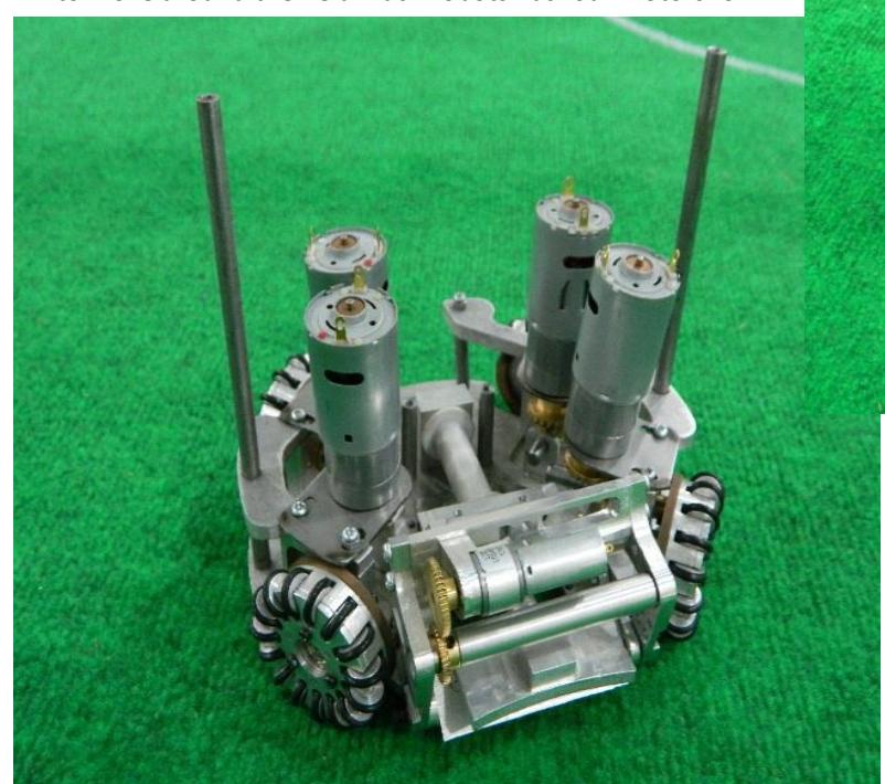
Our robots, Figure 1(a), figure 1(b)
Mechanical Information:
Height: 150mm Diameter: 175
Percentage of ball coverage: 18%
Our robots are equipped with 4-Omni directional wheels. Each is driven by a 12 Volt DC motor which helps our robot to move around the field. Each robots has four motors for the four wheels with gearhead 4:1 and one motor for the dribbler. Robot internally consists of a low resistance solenoid (for kicking mechanism), two single printed circuit boards, two lithium polymer batteries and a Microcontroller. There are total of three mechanism included in the
2.2 Dribbler
The dribbling device is round bar cover with aluminum connected to 12V DC motor, where dribbler covers the ball 18% of diameter.
2.3 Kicker
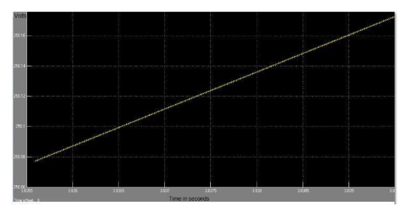
The kicking device consist of two parts both driven a same kicker board. Figure 2 shows the simulation result of boost capacitor charging. According to the simulation results capacitor is getting charged at 250V in 3.8s.
2.3.1 Flat kicker
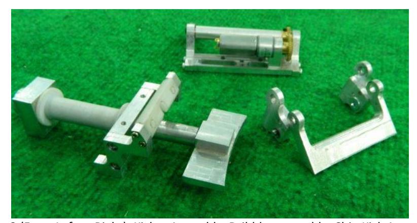
Flat kicker is a primarily method of both shooting and passing The flat kicker is a custom made cylindrical shaped solenoid which provides the force to a curved kicking plate. The solenoid is made using 25 AWG wire, according to the calculated results. It can shoot up to a velocity of 10m/s. The kicking speed of the ball is controlled by ON-OFF time of the switch. It is driven by two 2200uF capacitors.
2.3.2 Chip Kicker
The chip kicker is a custom made flat shaped solenoid which provides the force to the wedge. The solenoid is made using 25 AWG wire according to the calculated results. It can shoot up to a velocity of 8 m/s. The elasticity of the ball makes it little difficult for the partner to get the ball steadily. It is driven by two 2200uF capacitors.
2.3.3 Kicker
The kicker boards consist of Power Electronics Boost converter which boosts the voltage up to 250v and is connected to the solenoids (both cylindrical and flat) followed by the switches. It is controlled by the PWM switching signal generated by the microcontroller. The microcontroller also limits the voltage on the capacitor to 250 Volts, by controlling the switching signal. It also generates the pulse of required time period to impulse the kicker with the desired kicking force.
2.4 Controller
The robot hardware is controlled by dsPIC33FJ64MC804 microcontroller. Functions like PWM generation, Serial communication UART, SPI for motor driver, ADC for kicker are implemented using this board. The robot receive control commands from the computer using a 2.4GHz bidirectional wireless Xbee module.
A kicker board is a boost converter circuit using a small inductor. This board is separated from the main electronic board.
3 – Software
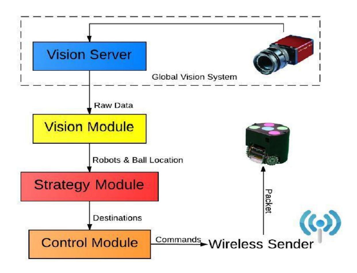
The overall software architecture is shown in the figure 4 below. Software consists of several modules organized in multi-layer.
3.1 Vision Module
We are receiving data from camera, directed to the SSL vision server, decoding the SSL vision packets at our AI server, where we have implemented a Kalman Filter to ensure the future predictions for ball position as well as opponent team robot positions. This data is sent to individual robots for them to see their own line of sight, if clear to move on with the next part of the algorithm, if possible.
3.2 Strategy Module
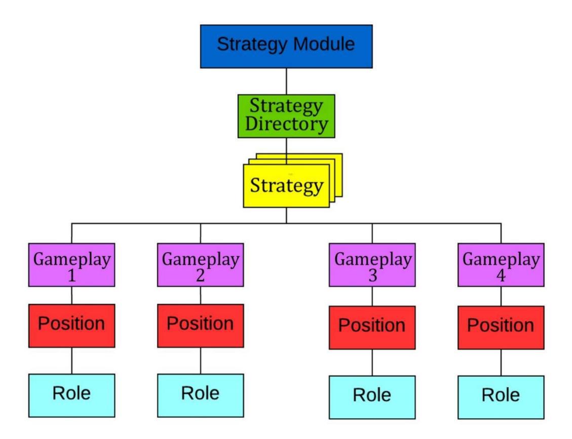
Strategy Module use vision data from Vision Module to figure out which one is the best tactic for particular situation. The structure of this module is based on STP framework.
The module contains a directory with different strategy of gameplays, a collection of different gameplays, when a strategy is selected, a gameplay of this strategy is then selected. In that gameplay the positions and roles of each player in the strategy is then sent to each player. The architecture of the Strategy Module is shown in Figure 5.
3.3 Role Definition
Four basic roles can define role of each robot during any gameplay: Attacker, Defender, Goalie and Mid Fielder. Each role is defined by their specific duty in the field.
Attacker is, as the name suggests an attacking player, will look for the ball and all and any attempts to score a goal. If the robot has the ball it will look for any and all opportunities to score a goal.
Goalie always remains in goalie box to prevent opposite team from scoring by blocking or intercept the ball. Another duty of Blocker is to clear the ball.
Mid Fielder is a robot that would have the basic duty to actually cover and manage the mid field area, roles include assisting the Attacker or assisting the defender will be decided on the nature of the game strategy.
Defender is the position that dedicated for defense. This player always remains around our defense zone and cooperate with Blocker to stop opponent from scoring. Defender tries to cover area as much as he can to ensure that the opponent robots can't score. Moreover, Defender also attempts to clear and intercept the ball whenever possible.
3.4 Control Module
Control Module is the module that gives control commands to all the robots, it uses the data from the vision module to send data of the ball and opponent robots for the motion path of the robot.
3.5 Wireless Sender
Commands which are generated by Control Module will be packed into single packet for each robot. Then, the wireless board will distribute packets via wireless signal and the robot will receive only the packet that sends for itself. These packets are transmitted to each robot via Xbee modules present on each robot and with the AI server.
4-References
Skuba Team – Mechanical Design Inspiration and help
robocupssl.cpe.ku.ac.th/_media/robocup2013:tdp:skuba_tdp_2013.pdf
Thanakorn Panyapiang, Ratthapoom Thanomyart, Kanjanapan Sukvichai and Suthinai Thanalerkchai, Skuba Team De-scription of the World RobCup 2013, Kasetsart University, Thailand.
Panyapiang, T., Lertariyasakchai, P., Chaiso, K., Sukvichai, K: A., et al., Skuba Team De-scription of the World RobCup 2012, Kasetsart University, Thailand.
References
- Skuba Team – Mechanical Design Inspiration and help. Available at: robocupssl.cpe.ku.ac.th/_media/robocup2013:tdp:skuba_tdp_2013.pdf
- Thanakorn Panyapiang, Ratthapoom Thanomyart, Kanjanapan Sukvichai and Suthinai Thanalerkchai, Skuba Team De-scription of the World RobCup 2013, Kasetsart University, Thailand.
- Panyapiang, T., Lertariyasakchai, P., Chaiso, K., Sukvichai, K: A., et al., Skuba Team De-scription of the World RobCup 2012, Kasetsart University, Thailand.